Development of the heat panel of the small space apparatus for navigation support

Author: V. V. Kolga, I. S. Yarkov, E. A. Yarkova
Journal: Siberian Aerospace Journal @vestnik-sibsau-en
Section: Aviation and spacecraft engineering
Article in issue: 3 vol.21, 2020.
Free access
To clarify the trajectory of the spacecraft in a given orbit, the parameter of unmodeled acceleration is taken into account. Today, in the design and manufacture of a spacecraft to meet the requirements of the technical specifications for the maximum allowable values of unmodeled accelerations during the operation of on-board equipment, it is necessary to take into account the effects of asymmetric heat fluxes from the panels of the spacecraft on the deviation of its center of mass from a given orbit. This article discusses the problem of the influence of asymmetric heat fluxes from the surfaces of the spacecraft emanating from the panels ± Z, + Y (deterministic and non-deterministic component) on the level of unmodeled accelerations, which significantly affects the trajectory of the spacecraft. In order to meet the requirements for the temperature control system in terms of ensuring efficient heat removal from the on-board equipment devices and its distribution over the surface of the instrument installation panel, it is necessary to significantly improve the technical characteristics of heat transfer and heat conduction processes in the spacecraft. The analysis of the current thermal control system in modern satellites is carried out and its shortcomings are revealed. A constructive option is proposed for creating an energy-intensive thermal panel, which allows more efficient heat removal from devices and distribution over the panel. The designed thermal panel is a flat sealed panel of a single complex design of aluminum alloy, made by the additive technology method. The dimensions of the thermal panel are limited by the structural dimensions of the working area of 3D printers. At the moment, the main dimensions reach 600-800 mm. An increase in the working area in the future will enable the installation of large-sized electronic equipment. A two-dimensional mathematical model for calculating heat transfer processes in the designed thermal panel is presented. For the calculation, specific average values are introduced that characterize the effective cross sections for the vapor channels and the wick in the longitudinal and transverse directions, physical parameters (porosity of the wick and its degree of liquid saturation).
Spacecraft, asymmetric heat fluxes, thermal control system, unmodeled accelerations, power thermal panel.
Short address: https://sciup.org/148321760
IDR: 148321760 | UDC: 536.2 | DOI: 10.31772/2587-6066-2020-21-3-382-388
Text of the scientific article Development of the heat panel of the small space apparatus for navigation support
Introduction. The development of space technology at the present stage is characterized by the creation of small spacecrafts for various purposes using a denser placement of payload devices, which affects the unevenness and asymmetry of heat fluxes from the panels of the spacecraft.
Placing electrical devices with a high heat flux density on small layout areas requires solving the problem of ensuring the operating temperatures of equipment, structure and spacecraft elements within strictly limited ranges at all operating modes of the thermal control system.
To meet the requirements for ensuring the guaranteed operating temperatures of the instrument seats, it is necessary to increase the efficiency of the thermal control system (TCS) by creating an energy-intensive panel that can remove heat and efficiently distribute it over the spacecraft panel.
Taking into account the influence of asymmetry of heat fluxes from the spacecraft panels in the spacecraft motion model leads to the creation of a more accurate and more reliable computational model of the spacecraft.
To meet the requirements of the technical design specifications for the permissible level of unmodeled accelerations arising during the operation of the spacecraft onboard systems, it is necessary to take into account the effect of asymmetric heat fluxes from instrument panels on the possibility of deviating the spacecraft center of mass from a given orbit.
The accuracy of determining the parameters of the spacecraft trajectory, in addition to the obvious limitation imposed by the composition of the available measurement information, substantially depends on the degree of correspondence of the dynamic model used for the numerical integration of the spacecraft motion equations to the real set of perturbations that form its trajectory.
To date, to refine the forecast of errors in the trajectory of the spacecraft movement along the orbit, such a parameter as unmodeled acceleration is used.
The total effect of unmodeled acceleration on the accuracy of calculations of spacecraft motion is quite significant. And, although the absolute value of unmodeled accelerations does not exceed 10–12÷10–13 km/s2, the resulting perturbations in the spacecraft coordinates can reach significant values [1]. The need to reduce the level of influence of unmodeled acceleration on the spacecraft trajectory requires the development of special measures to minimize this effect.
The problem of reducing the values of unmodeled accelerations arising from the influence of the operation of on-board systems has a high degree of relevance, since, on the one hand, it can serve to refine the already existing trajectories of spacecrafts, and on the other hand, when creating new vehicles, it will make it possible to refine and optimize the computational dynamic model, minimizing energy consumption for adjusting the working orbit (which will lead to a decrease in the total mass of spacecrafts) [2; 3].
Analysis of the current thermoregulation system. To reduce the level of unmodeled accelerations and take them into account in the computational dynamic model, we have developed an a priori model that allows us to clarify the physical processes of thermal radiation of onboard instruments and spacecraft systems, corrected and refined during flight tests. At the same time, it is necessary to take into account the correctness of setting the values of thermal and mechanical loads and the duration of the load cyclogram modes during «normal operation of the spacecraft», as well as the accuracy of the heat release cyclogram of the onboard equipment of the automatic voltage stabilization complex in terms of the absolute values of heat release and the duration of operating modes.
At the present time, the available estimate of the accuracy of the cyclograms of the heat release of the automatic voltage stabilization complex is up to 150 W and the duration of the modes is up to 4 hours.
Cyclograms are necessary to take into account the asymmetry of the spacecraft's own thermal supply, and at the same time should not exceed 10 W (short-term heat emissions) and 5 W (long-term heat emissions).
The processing of data from temperature sensors on board the spacecraft in order to calculate heat fluxes is a complex task from the methodological and computational point of view, the solution of which, taking into account the capacities of the onboard information computer complex, is not possible in space. Thus, the task of processing measurements of temperature sensors should be solved in the ground control complex.
At present, it is not possible to meet the requirements for minimizing unmodeled accelerations by existing TCS without additional energy costs and changes in the spacecraft dimensions. The implementation of this requirement should be carried out through new layout solutions at the spacecraft level, taking into account the precise determination of the values of heat fluxes and cyclograms of heat release onboard equipment.
To date, in navigation spacecraft they use a thermal control system [4–9], which is a honeycomb panel with a liquid collector built into it. The production of a three-layer honeycomb panel (with various types of honeycomb filler) is carried out using the following technology:
– production of component parts, including honeycomb filler, skins, reinforcing and embedded elements, heat pipes;
– joining (bonding) the surface of the shelves of heat pipes with sheathing using heat-conducting glue;
– connection (bonding) of sheathing with honeycomb core and built-in embedded elements.
The assembly (bonding) of the three-layer honeycomb panel is carried out on the technological equipment (table) through a special gasket. The required pressure is provided using a vacuum bag covered with a layer of thermal insulation.
Bonding is carried out in a thermal oven for the required time at an elevated temperature (about 125 °C), which is increased stepwise to the bonding temperature, thereby providing the required exposure (about 3 hours), and then gradually cooled to ambient temperature. In particular, film glue VK-51 TU1-596-212–85 is used to bond the sheathing with honeycomb core
The analysis showed that in the manufacture of largesized three-layer honeycomb panels with thin aluminum skins, it is first of all necessary that the technological equipment used be made with a high degree of flatness and surface cleanliness, and that spacers made of aluminum sheet were used to exclude the influence of the difference in the coefficient of thermal linear expansion between equipment and honeycomb panel.
The disadvantage of the said method is the possibility of using this technology for honeycomb panels with dimensions only up to 2000 × 3000 mm. When polymerizing large panels, it is necessary to use composite backing sheets.
Due to an increase in the overall dimensions of honeycomb panels (up to 3000 × 6000 mm), as well as a decrease in the thickness of the skins (down to 0.3 mm) used for modern spacecrafts, and the need to improve the geometric accuracy of the working surface, the use of solid large-sized sheets, on the one hand, is unprofitable, given the high cost of their manufacture and delivery, on the other hand, it does not provide the required accuracy (the overall flatness of the panel is not more than 1.5 mm, the flatness is 0.1 mm at a size of 200 × 200 mm). Such stringent requirements are due to the long period of active existence of the spacecraft (up to 15 years), the troublefree operation of satellite instruments installed on the working surface of the honeycomb panel through heatconducting paste. In this case, the temperature difference between the mounting surface of the device and the casing should be minimal, therefore, the flatness of the panel should be as small as possible.
Thus, a significant disadvantage of the said method is the complexity of manufacturing and insufficiently high quality of honeycomb panels of large dimensions. Engineering approaches aimed at solving this problem lead to the need to reduce the overall dimensions of the honeycomb panel and change its design to ensure more efficient heat removal from the onboard equipment.
The calculated values of the operating temperatures of the equipment based on the results of the thermal analysis of the spacecraft must meet the requirements for the calculated uncertainty, while the calculated uncertainty is taken basing on the devices belonging to the temperature group.
The current TCS does not provide a uniform efficient heat removal from the spacecraft devices, «hot» spots with extremely high power consumption of the devices are created, the equipment overheats.
Asymmetric heat fluxes from the spacecraft surfaces, emanating from the ±Z, +Y panels (deterministic and non-deterministic components), in turn, contribute to the value of the level of unmodeled accelerations from various onboard systems, which significantly affects the spacecraft trajectory.
To solve this problem, we propose to use the heatconducting panels developed by us, which increase the efficiency of heat removal from radio-electronic equipment on board the spacecraft and have, at the same time, much smaller dimensions. When working with such structures, it is necessary to develop a computational algorithm for assessing the removed heat fluxes under different operating modes of distribution of the heat load on the panel surface. This algorithm is necessary both at the stage of spacecraft development using such structures in the thermal control system and in determining the optimal arrangement of spacecraft instruments and equipment.
This paper presents a two-dimensional mathematical model of heat transfer in a thermal panel. On the basis of the model, an algorithm is described for assessing the performance of the panel by capillary limitation for a given distribution of heat flux density on the surface. The model allows to obtain the temperature field distribution on the panel surface.
Power thermal panel design. The power thermal panel is a flat sealed panel, which is a single complex structure of aluminum alloy, made by the method of additive technologies and consisting of two cross channels with wicks, a porous structure, closed on all sides with a thin layer of aluminum. The dimensions of the thermal panel are limited by the structural dimensions of the working area of 3D printers. At the moment, the main dimensions are up to 600–800 mm. An increase in the working area in comparison with hyper-heat-conducting panels [10], the size of which reaches 100 × 300 mm, makes it possible to install large-sized electronic equipment.
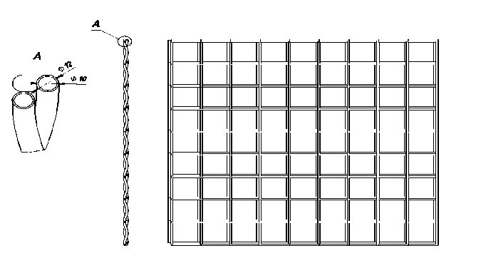
The structure of the channels inside the power thermal panel
Строение каналов внутри силовой термопанели
In this case, the internal structure of the panels is such that the coolant moves freely over the entire plane of the panel inside the cruciform channels with wicks filled with a working fluid (ammonia, water, etc.) (see fig.). Heat transfer along the panel is carried out due to the movement of the working substance in the form of vapor from the heating area to the condensation area through the vapor channels and back, in the form of a liquid through the wick. The main feature of a phase change thermal panel is a highly efficient heat removal system and an even temperature distribution over the panel surface with a difference of up to 1–2 ºC. When heated, the liquid heat transfer agent begins to evaporate and in the form of vapor moves to the evaporation zone, then condenses, moves through the wick in the form of a liquid to the heating zone, thus distributing heat over the panel. The movement of the working substance is carried out by capillary forces, which does not require the use of pumps and complex circuits for pumping coolant.
The capillary head of the wick must exceed the sum of the pressures arising in the liquid moving along the wick and in the vapor moving along the vapor channels. In the opposite case, the wick under the heat-generating element is drained, and the effective thermal conductivity of the panel drops sharply.
The technology for manufacturing a power thermal panel involves the modernization of its configuration by introducing internal vapor channels with a wick, the specific dimensions of which are unknown and are selected experimentally.
For the calculation, specific average values are introduced that characterize the effective sections for vapor channels and wick in the longitudinal and transverse directions, physical parameters (porosity of the wick and the degree of its saturation with liquid).
Mathematical model. Let us introduce the values characterizing the effective longitudinal and cross sections for vapor channels and the wick [11–15]. Let us define the following values to describe the vapor move- ment: Svx, Svy – the fraction of the effective section of the vapor channel from the total section of the panel for the longitudinal direction x and transverse y, respectively. Similarly, for describing the fluid motion: Slx, Sly – the fraction of the effective section of the wick from the total section of the panel for the longitudinal direction x and transverse y, respectively. The Svx, Svy, Slx, Sly values are dimensionless and can be from 0 to 1.
The input conditions for the problem are the heat flux to the panel surface Q ( x , y ), where x ∈ [0, H ], y ∈ [0, W ]. Values H , W are the panel length and width. It follows from the stationarity of the problem that the amount of the evaporating coolant from the wick to the vapor channels per unit area at each point of the panel is equal to m 1 = Q/ X, where X is the latent heat of pore formation.
For the movement of fluid in the wick, you can write the mass conservation equation:
div m l = - in 1/ D , (1)
where m l = ( m lx , m ly ) is the fluid mass flow inside the wick, D is the panel thickness minus the panel body wall thickness.
To describe the movement of the gas phase of the coolant, we use a formula similar to (1):
div m v = m 1/ D , (2)
where m v = ( m vx , m vy ) is the vapor mass flow in the vapor channels.
The panel will work successfully if the pressure difference between the gaseous and liquid phases at each point is less than the capillary pressure
P c =
2 σ cos θ rc
where rc is the radius of the pores of the wick, σ is the coefficient of surface tension, θ is the minimum angle of wetting of the material of the wick by the coolant.
It is possible to find the pressure distributions in the gaseous and liquid phases Pv(x, y) and Pl(x, y) up to a constant. Since there is a point (xmin, ymin) inside the panel (in the area of the condenser) at which Pv = Pl can be taken, the pressure difference between the gaseous and liquid phases can be written as follows
∆P = P v ( x , y ) – P l ( x , y ) –
– ( P v ( x min , y min) – Pl ( x min , y min )).
If max ( ∆P ) > Pc , then capillary forces will not be able to pull up the coolant, the wick in the panel will dry out and the panel will not work satisfactorily
Thus, the capillary condition for the panel operation can be written as follows:
max( ∆P ) < P c . (5)
The temperature distribution on the panel surface will be determined by the saturated vapor temperature at a given point, the heating power density and the thermal resistance of the wick layer and the panel body:
T ( x , y ) = T s ( P v ( x , y )) + Q ( x , y ) R , (6)
where R = R f + R w is the sum of the thermal resistances of the wick and the panel body wall. The thermal resistance of the wick can be estimated: R f = c /k f , where c is the thickness of the wick (distance from the steam channel to the surface), k f is the thermal conductivity of the wick filled with a coolant.
The thermal resistance of the wall is: R w = t / k w , where t is the wall thickness, k w is the thermal conductivity of the panel body material.
The transfer of a laminar flow of fluid in a porous wick, depending on the type of wick, is determined either by Darcy's law (for liquids obeying the Navier-Stokes law)
-^P - П й + P f = 0, (7)
k div u = 0, or Poiseuille's law (one of the simplest exact solutions of the Navier-Stokes equations).
Q = π R 4 ( P 1 – P 2 ) = π d 4 -∆ P . 8 η l 128 η l
The kinetics of the liquid-vapor phase transition, i.e. the rate of evaporation and condensation can be determined using the Kn criterion (the Knudsen number). Maximum heat flux during evaporation from a flat surface to vacuum
LP ж q max = f , 2 π RоT ж / µ
where R 0 is the universal gas constant, L is the latent heat of vaporization. In some cases, the transfer of energy and matter in heat pipes can occur with partial drying of a porous wick. As a result, the calculation of the heat pipe is based on the equations of the dynamics of the flow of liquid and vapor, the description of the kinetics of phase transitions at the liquid-vapor interface, as well as the equations of energy transfer in the arteries of the tube, in the capillary-porous part (wick) and in the pipe shell itself.
The flow of fluid in the porous body of the wick should be described in more detail by Darcy's law m = pжVж= – Kж gradP . (10)
µ ж
By integrating this equation, we get the pressure drop at two points of the wick. Permeability K ж depends on the porosity П of the wick and the degree of its saturation with liquid bж
K ж = ƒ (П, b ж ). (11)
Another characteristic of a porous body is the differential curve of the distribution of surface permeability f ( K ) (similar to the distribution curve of pores along the radius). For a homogeneous material, such a curve can be represented as a delta function of K or a linear combination of these functions
N f ( K ) = ∑ δ Ai , i = j
N
Ai satisfies the condition ∑ Ai = 1 , N is finite. (12) i = 1
If f ( K ) cannot be represented as a finite number of functions, then the material is heterogeneous. If f ( K ) is represented by one term, the material is homogeneous. If a material is described by two or more functions f ( K ), then it is heterogeneous. If f ( K ) depends on rectangular coordinates xi ( i = 1,2,3) and angular coordinates Ψ, θ, then the porous material is anisotropic. If there is no dependence on angular coordinates, the material is isotropic
K 2
P ( K 1 ≤ K ≤ K 2) = ∫ f ( xi θψ ) dxid θ d ψ . (13)
K 1
Conclusion. The presented mathematical model of heat transfer processes in a thermal panel allows one to predict various modes of operation of a heat transfer device for high-temperature cycles.
Thus, the use of a new design of a thermal panel in small spacecraft will not only solve the problem of irregularity and asymmetry of heat fluxes from spacecraft panels, but also ensure the requirements of the technical specification for the limiting level of unmodeled accelerations during onboard systems operation.
References Development of the heat panel of the small space apparatus for navigation support
- Beloysov L. U. Ocenivanie parametrov dvizheniya kosmicheskih apparatov [Estimation of motion parameters of spacecraft]. Moscow, Fizmatlit Publ., 2002, 216 p.
- Malahovskij E. E., Poznyak E. L., Shulyaka A. A. [Flexible controlled apparatus with disturbances from internal sources]. Kosmicheskiye issledovaniya. 1995, Vol. 33, No. 5, P. 538–545 (In Russ.).
- Maximov I. A. [Problems of support of reliable operation of modern spacecraft under factors of space and technogeneous character destabilizing influence]. Vestnik SibGAU. 2010, Vol. 30, No. 4, P. 100–101 (In Russ.).
- Caplin S. V., Bolychev S. A. [A system for providing thermal conditions for an experimental model of an optical-telescopic complex of a spacecraft]. Vestnik SamGU. 2013, No. 9/2(110), P. 236–243 (In Russ.).
- Alekseev N. G., Zagar O. V., Kas’yanov A. O. [A system for ensuring the thermal regime of the device with temperature control in a narrow range]. Мaterialy XI Mezhdunar. nauch. konf. “Reshetnevskie chteniya” [Materials XI Intern. Scientific. Conf “Reshetnev reading”]. Krasnoyarsk, 2007, P. 213 (In Russ.).
- Kosenko V. E, Zvonary V. D., Suntsov S. B., Derevyanko V. A., Vasilyev E. N., Nesterov D. A. [The use of hyper-heat-conducting structures in the development of leaky space vehicles of increased power and resource] Мaterialy XVII Mezhdunarodnoy nauchnoy konferencii “Sistemnyy analiz, upravlenie i navigaciya” [Materials XVII International Scientific Conference “System analysis, management and navigation”]. Evpatoria, 2012, P. 20–22 (In Russ.).
- Kosenko V. E, Zvonary V. D., Suntsov S. B., Chebotarev V. E., Fatkulin R. F., Bakirov M. T., Derevyanko V. A., Makukha M. V. [The Results of Using Heat-Conductive structures in the apparatus of spacecraft]. Мaterialy ХXI Mezhdunarodnoy nauchnoy konferencii “Sistemnyy analiz, upravlenie i navigaciya” [Materials ХXI International Scientific Conference “System analysis, management and navigation”]. Moscow, MAI, 2016, P. 45–47 (In Russ.).
- Meseguer J., Perez-Grande I., Sanz-Andres A. Spacecraft thermal control. Cambridge, UK: Woodhead Publishing Limited, 2012. 413p.
- Analysis of efficiency of systems for control of the thermal regime of spacecraft / A.V. Delkov et al. Chemical and Petroleum Engineering. 2016, No. 9, P. 714–719.
- Suntsov S. B., Kosenko V. E, Derevyanko V. A. Modul’ radioelektronnoj apparatury s giperteploprovodyashchim osnovaniem [The module of electronic equipment with hyperthermally conductive]. Patent RF, no 2403692, 2009.
- Vasilyev E. N., Derevyanko V. A., Nesterov D. A., Kosenko V. E., Chebotarev V. E. [Computational modeling of heat exchange processes in thermal control systems of spacecraft]. Vychislitel'nyye tekhnologii. 2009, Vol. 14, Iss. 6, P. 19–28 (In Russ.).
- Delcov A. V., Hodenkov A. A., Zhuikov D. A. Mathematical modeling of single-phase thermal control system of the spacecraft. Proceedings of 12th Intern. Conf. on Actual Problems of Electronic Instrument Engineering. APEIPE 2014, P. 591–593.
- Tanasienko F. V., Shevchenko Y. N., Delikov A. V., Kishkin A. A. [Two-dimensional thermal model of the thermal control system for nonhermetic formation spacecraft]. Siberian Journal of Science and Technology. 2018, Vol. 19. No. 3, P. 445–451 (In Russ.).
- Kraev M. V., Zagar O. V., Kraev V. M., Golikovskaya K. F. Nestacionarnye teplovye rezhimy kosmicheskih apparatov sputnikovyh system [Non-stationary thermal conditions of spacecraft of satellite systems]. Krasnoyarsk, 2004, 280 p.
- Faghri A. Heat Pipe Science and Technology. Taylor and Francis Group, 1995, 874 p.
