Development of three-point aviation fuel quantity gauge

Author: Akzigitov R.A., Statsenko N.I., Pisarev N.S., Efimova A.N.
Journal: Сибирский аэрокосмический журнал @vestnik-sibsau
Section: Авиационная и ракетно-космическая техника
Article in issue: 2 т.19, 2018.
Free access
In response to the well-developed digital technologies, modern methods can be worked out for the spheres where radical changes seemed hardly possible. This paper describes the development of a new method of fuel quantity meas- urement that has not been applied before. To measure the level of fuel in the fuel tank of an aircraft, it is proposed to use three fuel level gauges and a special electronic calculation unit; they model the fuel level surface inside the given volume, and then the actual amount of fuel can also be calculated. This can considerably reduce the evaluation errors allowed with the application of the existing fuel quantity gauges. The main advantage of the system offered is the elimi- nation of the errors arising with the aircraft evolutions and irregular motions. The article gives the analysis of the fuel level assessment methods used in the aviation sphere at present, the types of fuel quantity gauges used in aviation, and the specific conditions of measuring the fuel level in the aircraft fuel tanks. The proposed method has a number of advantages, in comparison with the traditional ways of measuring the fuel level; a basic mathematical model of the aircraft tank fuel level calculation has also been worked out.
Fuel quantity gauge, fuel tank, error, aircraft, measurement
Short address: https://sciup.org/148321836
IDR: 148321836 | UDC: 629.7.066.3 | DOI: 10.31772/2587-6066-2018-19-2-246-250
Разработка трёхточечного авиационного топливомера
Благодаря хорошо развитым на данный момент цифровым технологиям становится возможным создание новых, современных методов в тех сферах, где, казалось бы, уже больше нечего менять. Данная статья по- священа разработке нового, несуществующего на данный момент, метода измерения топлива. Для измерения топлива предлагается использовать три топливных датчика и вычислительный элемент для моделирования положения уровня топлива в пространстве с дальнейшим расчетом объёма топлива, что позволит умень- шить погрешности, возникающие при эксплуатации топливомеров. Главным преимуществом данной системы будет устранение погрешности, возникающей при эволюциях воздушного судна, а также при его неравномер- ном движении. Рассмотрены способы замера уровня топлива, используемые в авиационной сфере в настоящее время, виды то- пливомеров, применяемых в авиации, а также особенности измерения уровня топлива. Предложенный способ обладает рядом преимуществ, в сравнении с традиционными способами замера уровня топлива, в статье представлена математическая модель, на основе которой будет производиться измерение уровня топлива в топливном баке воздушного судна.
Text of the scientific article Development of three-point aviation fuel quantity gauge
Introduction. Fuel quantity gauge is an instrument that measures the volume or weight of fuel or oil in tanks. It is used to measure the level of fuel in land transport and aircraft, in contrast to level gauges measuring the level of liquids or bulk materials in various tanks and storage facilities.
As a rule, direct measurement of the amount of fuel meets a lot of impediments, that is why indirect measurements are widely used, such as measuring the surface level or fuel pressure inside the tank [1–6].
Among the features of measuring the fuel level, we can note the following:
-
– fuel tank volumes are limited – that imposes restrictions on the level sensors in use;
-
– fuel tanks come in different shapes, sometimes quite irregular – that is the reason for using profiled level sensors;
-
– external forces and accelerations cause redistribution of fuel inside the tank – that provokes measurement errors;
– for aircraft with several fuel tanks, it is necessary to relocate the center of fuel load by pumping fuel from one tank into another; that is necessary to stabilize the center of mass of the aircraft [7; 8].
Aviation fuel level gauges. At the present time there are several types of fuel gauges in use, they are divided according to the method of measurement and the field of use. There are two main types of fuel gauges most widely used in aviation:
– capacitive fuel gauges – the operational principle of that gauge type is based on the significant difference in the dielectric properties of air and fuel (fig. 1);
– float-type fuel gauges – the operational principle of that gauge type is based on registering the position of the slider on the variable resistance which is moved by a lever with a float – a plastic or metal hollow unit floating on the surface of the fuel.
Indirect measurements of the fuel level in the tank and conversion of the obtained value into an analog signal make it possible to measure the fuel level in the aircraft tank [9; 10].
Modern fuel gauges have the errors induced by irregular movement of the aircraft and its deviations from the horizontal plane. These errors can be eliminated by applying a different method of fuel measurements.
Three-point method of fuel measurement. The aim of this method is elimination of the errors in situation when the fuel surface deflects from its normal position (the level when the fuel is not affected by external forces).
The three-point method of fuel measurement implies the use of three fuel gauges and an electronic calculation unit with pre-specified geometry characteristics of the fuel tank. Thanks to modern digital technologies and thoroughly worked-out mathematical methods, we can make a mathematical and virtual model of the fuel tank [11–14]. Using three fuel gauges we can measure the height of the fuel level in three different locations inside the tank; that allows to determine three points of the surface level of the fuel (fig. 2).
According to the space coordinates of the three points inside the fuel tank, a simulation of the fuel surface plane can be produced by the digital unit. This model plane will cut off the upper (empty) part of the fuel tank. With
the help of the specified mathematical methods, the form of the modelled truncated figure (truncated fuel tank) allows to calculate its volume. To make the calculation, it is necessary to divide the fuel tank into identical segments and state the fuel level value in each segment. According to the obtained parameters of the area of the segment and the fuel level in it, the volume of the fuel content in this segment can be determined (fig. 3).
Mathematical model of a three-point fuel level gauge. To determine the fuel level height in each segment, we use equation of plane for three points [15]:
( x — x 0 )
У 1 + У 0
z 1 + z 0
У 2 — У 0
z 2 - z 0
+ ( z — z 0 )
— ( У — У 0 )
x 1 + x 0
У 1 + У 0
x 1 + x 0
z 1 + z 0
x 2 — x 0
У 2 — У 0
= 0;
x 2
z 2
-
x
+
- z 0
xA — yB + zC + D = 0;
xA — yB + D = — zC ;
- xA + yB — D z = C ’
where A , B and C are the values of the determinants of equation of plane, and D is determined as follows:
D = — x 0 A + y 0 B — z 0 C ,
_ — xiA + ykB — D zik
When the fuel level in each segment is stated, it becomes possible to determine the total volume occupied by the fuel in the fuel tank:
nm
V = 5 x EE z k
k = 1 i = 1
= 5 X
nm
ZE
k = 1 i = 1
— xi A + yk B — D
C ,
s is the area of a separate segment, n , m are the maximum number of segments formed along the X and Y axes.
However, the calculation of the real model will not coincide with the actual summing up, as the tank is of a confined volume at the top and at the bottom.
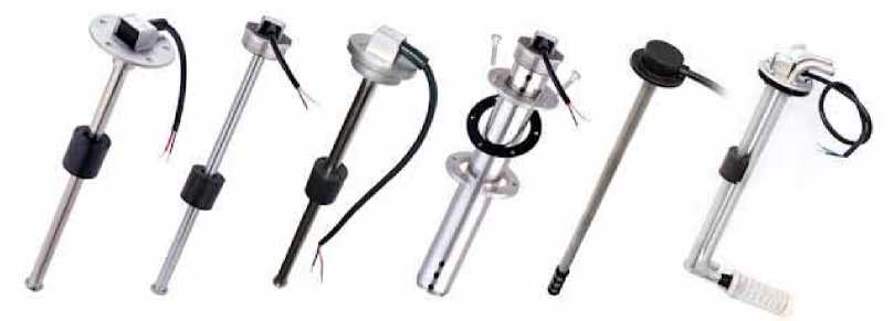
Fig. 1. Capacitive fuel gauges
Рис. 1. Емкостные топливомеры
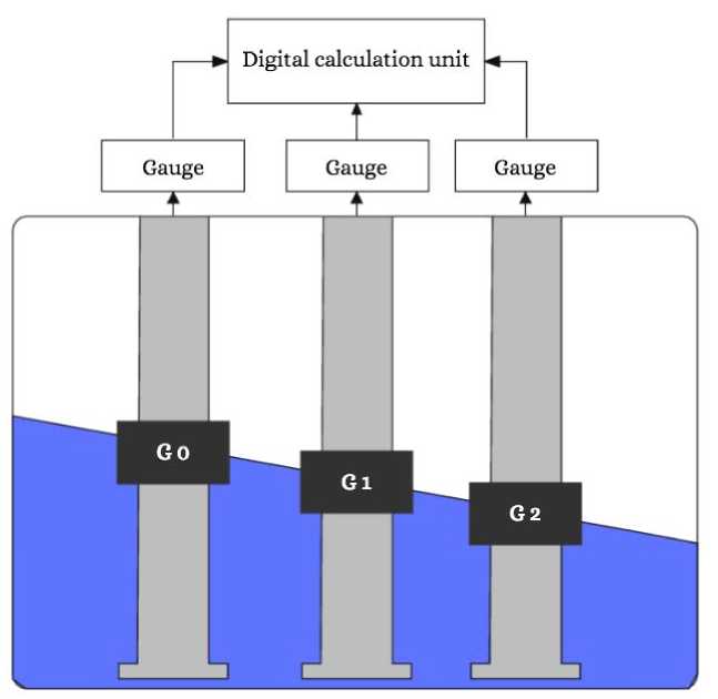
Fig. 2. Three-point fuel-content indication method scheme
Рис. 2. Функциональная схема трехточечного топливомера
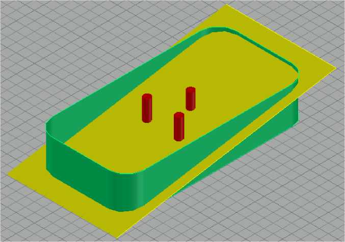
Fig. 3. Section of the fuel tank volume by the fuel level plane
Рис. 3. Сечение топливного бака плоскостью уровня топлива
The resulting fuel level plane may go across the top and bottom surfaces of the tank, which will cause an error in the calculations.
When calculating each segment, its maximum and minimum values on the Z axis will be taken into account.
Fig. 4 shows the fuel tank horizontal cross-section. The color of the segments corresponds to the fuel level in each segment:
-
– black – H = 0;
-
– yellow – H = Z;
-
– white – H = max.
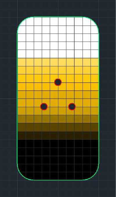
Fig. 4. Fuel tank horizontal cross-section
Рис. 4. Топливный бак в горизонтальном сечении
When the fuel level surface deflects from the horizontal plane, some of the tank segments may become empty (black color); then, according to equation of the plane, the value of the z coordinate will be negative, and the value of the volume will also become negative in this case. To avoid this, in case when Z takes a negative value, the given segment will be equated to zero. When the fuel level in the segments comes to its maximum (white color), and according to equation of plane, the z coordinate takes a value greater than maximum, Z will be equated to the maximum value for the given segment.
Conclusion . With the given corrections, it becomes possible to make calculations of the greatest accuracy. It is obvious that the virtual truncated model will correspond to the actual level of the fuel in the tank, and the error in case of the external forces effect will not arise, as the virtual model will show the slope of the cross-section plane with no change in the volume.
References Development of three-point aviation fuel quantity gauge
- Григоровский Б. К., Кацюба О. А., Припутни-ков А. П. Отображение модельным рядом топливоме-ров многообразия информационно-измерительного процесса. Репрезентативность отображения//Вестник САМГУПС. 2015. Вып. 2, № 2. С. 150-155.
- Емкостные датчики уровня электропроводящей жидкости/А. А. Джежора //Датчики и системы. 2008. № 12. С. 26-29.
- Математические модели и методы обработки измерительных сигналов емкостных преобразователей на постоянном токе/М. А. Мастепаненко, И. Н. Воротников, С. В. Аникуев. Ставрополь: АГ-РУС, 2015. 232 с.
- Джежора А. А., Рубаник В. В., Савчук В. К. Контроль уровня топлива//Вестник Полоцкого государственного университета. - 2010. - № 2. С. 21-25.
- Богоявленский А. А. Инструментальный контроль запаса и расхода рабочих жидкостей при технической эксплуатации воздушных судов//Мир измерений. 2017. № 4. С. 16-23.
