Development of tunable band noise genera-tors

Author: Dremukhin M.A., Kuzovnikov A.V., Strekaleva T.V.
Journal: Siberian Aerospace Journal @vestnik-sibsau-en
Section: Informatics, computer technology and management
Article in issue: 2 vol.23, 2022.
Free access
The aim of the work is to develop and study the principle of operation of tunable band noise generators (TBNG) and their characteristics, a noise signal conditioner of a modular type, which provides controlling the bandwidth of a noise signal for using it as a means set-ting radio noise. It is possible to do it through the formation and radiation in the surrounding space of electromagnetic fields of the energy spectrum in specified frequency ranges, with the possibility of changing the amplitude and bandwidth of the signal. To improve performance and make them more widely used in order to provide high-quality counteraction to unauthor-ized removal (by intruders) of information on emission channels of spurious electromagnetic radiation (SER), it is necessary to create multichannel adaptive TBNGs. In the developed generators in each noisy channel, it is possible to provide power adjustment, generated noise signal and noise bandwidth control, which will improve the electromagnetic compatibility of such devices. To ensure this, it is proposed to use a design concept based on the use of con-trolled modules of noise sources with band-pass filters, which also allows you to get a noise signal uniform in amplitude.
Noise generator, noise signal, SER
Short address: https://sciup.org/148329617
IDR: 148329617 | UDC: 621.373.1 | DOI: 10.31772/2712-8970-2022-23-2-156-167
Text of the scientific article Development of tunable band noise genera-tors
Noise generators (NG) are used for active information protection - the production of various types of interference [1-2]. Noise generated by a generator disguises a useful signal so that it becomes a very difficult task to distinguish it from a general signal [3-4]. If the signal generated by a generator is not random, dips in the spectral characteristic can be seen on the spectrum analyzer. This is a vulnerability in the information protection system built with the help of these NGs, because there is a technical possibility to build a comb filter and isolate the undistorted part of the useful signal [5-7].
With the improvement of the computer aids (CA) for processing information of limited distribution, it seems relevant to create highly effective NGs, for active protection of information and masking of SER [8-9]. Side radiations are formed due to the imposition of informative signals on parasitic signals of internal devices and CA units or the emission of informative signals in an explicit form [10-11]. The developed NGs should be able to ensure, on the one hand, the safety of information radiated through SER channels [12], and, on the other hand, to ensure electromagnetic compatibility of the technical means of active information protection with other radio engineering devices and telecommunication systems.
Currently, there are a large number of certified NGs on the market for active information protection. At the same time, such devices are structurally single-band NGs masking interference, with the sufficiently wide band of noise signal emission and the maximum operating frequency from 1 GHz to 2.5 GHz [13-15]. This is clearly not enough, since clock frequencies of the same computers are constantly increasing, which leads to the expansion of the frequency range radiation. In this regard, the issue of electromagnetic compatibility of GPS and other radio transmitting and receiving devices is relevant. The emission of a noise signal outside the operating band must be minimal and meet the requirements of the State Committee on Radio Frequencies, which defines the norms for the spectral power of the GS radiation. In addition, it is irrational to have a large number of band-pass NGs at close frequencies within the same range, since this significantly complicates the design of a complex, as well as its control system. In this case, it is advisable to use a TBNG with the maximum operating frequency of up to 5 - 8 GHz.
The main part
The TBNG complex is designed for radio interference in the frequency range from 200 MHz to 6 GHz with the ability to adjust an output signal, both in frequency and amplitude. The complex functions autonomously; if it is necessary, the operation of the complex is controlled by an operator. Technical characteristics of the TBNG complex are given in Table 1.
Structurally, the TBNG unit consists of the following functional units: noise source modules, filters, adder module, pre-amplifier module, output power amplifier module, control module, power supply unit, supply voltage conversion units, feeder line and antenna unit, cooling system fans. The block diagram of the TBNG unit is shown in fig. 1.
Table 1
Technical characteristics of the TBNG complex
|
№ letters |
Overlap range, GHz |
The working band of the barrier, not less than, MHz |
Integral power at the input of a radiating antenna, not less than, W |
|
1 |
0,2 to 1,5 |
100 |
3 |
|
2 |
1,5 to 2,5 |
||
|
3 |
2,5 to 4,0 |
||
|
4 |
4,0 to 6,0 |
200 |
Network 220 V, 50 Hz
LAN USB
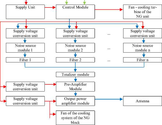
Рис. 1. Структурная схема блока ПДГШ
-
Fig. 1. Structural diagram of the TBNG block
The main part of the TBNG is an NG block, which consists of a set of band-pass NG and an adder module. The composition of the band-pass NG includes an controlled noise source module and a bandpass filter. The controlled noise source module consists of a supply voltage conversion unit (SVCU) and a noise source module (NSM). The SVCU supplies control voltage to the NSM, thereby creating the amplitude of the noise signal. The NSM is the main source of noise, the principle of operation of which is based on the creation of a noise signal in the p-n junction "base - emitter" of a transistor consisting of components: thermal, shot. Thermal noise is caused by vibrations of carriers in a conductive medium under conditions of thermal equilibrium. Shot noise is a consequence of the discreteness of charge carriers and the randomness of their formation.
The number of band NG depends on the number of working bands embedded in the TBNG, in which each bandpass filter is set to its own working noise bandwidth. All noise signals from the bandpass NG are sent to the adder module, in which the pre-gain is combined with the output power gain to obtain the working barrage band. This design concept of the TBNG allows you to narrow the band of the emitted noise signal to the minimum required values with the ability to work at fixed frequencies, and in the mode of passive selection and adjustment of the operating frequency within the established operating range, which increases the efficiency of their operation.
The results of NG measurements
To confirm the performance characteristics of the TBNG, measurements were carried out for all the developed NGs in each sub-band of frequency overlap using controlled modules of noise sources with switchable bandpass filters.
The measurements of the width of the direction pattern (DP) of the emitting antennas of the TBNG were carried out in an anechoic shielded chamber. The antennas deployed on mast devices, when measuring the bottom in the horizontal plane, are installed on a rotary platform in the working position using a non-conductive support. To measure the radiation pattern, the measuring equipment is connected according to the scheme shown in fig. 2.
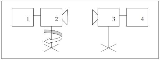
Рис. 2. Схема проведения измерений:
1 – генератор; 2 – исследуемая антенна; 3 – вспомогательная антенна; 4 – измерительный приемник
-
Fig. 2. Measurement scheme:
1 – generator; 2 – antenna under study; 3 – auxiliary antenna; 4 – measuring receiver
The auxiliary antennae and the antennae being studied have the same radiation polarization. When measuring the parameters of a directional radiation antenna, the distance between the receiving and transmitting antennas must satisfy the inequality:
R> 2( D i + D 2)2 X
where D 1 is the largest of the linear dimensions of the antenna under test; D 2 is the largest of the linear dimensions of the receiving antenna; λ is a wavelength.
The measuring surface is a flat area on the surface of the earth with uniform electrical characteristics, and is also free of reflective objects in a sufficiently large area so that errors during testing are minimized. The influence of extraneous electromagnetic fields on the accuracy of the measurement results was also excluded and the grounding of the measuring platform was ensured.
With the help of a rotary device, the test antenna is rotated at intervals around the axis by 360 ° for the horizontal plane of the antenna and by 60 ° for the vertical one. The value of the interval is no more than 10 °. For each turn of the antenna, three measurements were carried out for each frequency being studied (lower - 0,2 GHz, central - 0,75 GHz and upper - 1,5 GHz) for the character № 1.
Each time the antenna under test is rotated by an angle, the voltage of the received signal is recorded according to the readings of the measuring receiver connected to the auxiliary antenna. Based on the measurement results, a graph of the DP was plotted in the polar coordinate system depending on the angle of rotation. Tables 2 and 3 show the voltage values of the signal received from the antenna being studied only in the 0,2 GHz range.
Table 2
Horizontal plane of the antenna being studied
|
Antenna rotation, ° |
P , dBm |
P , dBm |
P , dBm |
P av , dBm |
|
Frequency 0,2 GHz |
||||
|
0 |
–83,79 |
–83,72 |
–84,07 |
–83,86 |
|
10 |
–83,71 |
–83,70 |
–83,75 |
–83,72 |
|
Antenna rotation, ° |
P , dBm |
P , dBm |
P , dBm |
P av , dBm |
|
20 |
–83,64 |
–83,59 |
–83,84 |
–83,69 |
|
30 |
–83,75 |
–83,61 |
–84,31 |
–83,89 |
|
40 |
–83,69 |
–83,63 |
–83,93 |
–83,75 |
|
50 |
–83,63 |
–83,68 |
–83,43 |
–83,58 |
|
60 |
–84,03 |
–83,94 |
–84,39 |
–84,12 |
|
70 |
–84,25 |
–84,11 |
–84,81 |
–84,39 |
|
80 |
–85,06 |
–85,05 |
–85,10 |
–85,07 |
|
90 |
–85,29 |
–85,21 |
–85,61 |
–85,37 |
|
100 |
–86,02 |
–85,88 |
–86,58 |
–86,16 |
|
110 |
–86,49 |
–86,53 |
–86,33 |
–86,45 |
|
120 |
–86,61 |
–86,55 |
–86,85 |
–86,67 |
|
130 |
–87,97 |
–87,85 |
–88,45 |
–88,09 |
|
140 |
–88,32 |
–88,24 |
–88,64 |
–88,40 |
|
150 |
–88,84 |
–88,71 |
–89,36 |
–88,97 |
|
160 |
–89,31 |
–89,23 |
–89,63 |
–89,39 |
|
170 |
–90,13 |
–90,19 |
–89,89 |
–90,07 |
|
180 |
–90,09 |
–90,03 |
–90,33 |
–90,15 |
|
190 |
–88,76 |
–88,65 |
–89,20 |
–88,87 |
|
200 |
–90,04 |
–90,10 |
–89,8 |
–89,98 |
|
210 |
–90,02 |
–90,07 |
–89,82 |
–89,97 |
|
220 |
–90,68 |
–90,62 |
–90,92 |
–90,74 |
|
230 |
–90,23 |
–89,99 |
–91,19 |
–90,47 |
|
240 |
–91,02 |
–91,21 |
–90,26 |
–90,83 |
|
250 |
–90,35 |
–90,22 |
–90,87 |
–90,48 |
|
260 |
–91,22 |
–91,26 |
–91,06 |
–91,18 |
|
270 |
–90,56 |
–90,65 |
–90,20 |
–90,47 |
|
280 |
–88,69 |
–88,62 |
–88,97 |
–88,76 |
|
290 |
–88,65 |
–88,55 |
–89,05 |
–88,75 |
|
300 |
–86,51 |
–86,64 |
–85,99 |
–86,38 |
|
310 |
–85,72 |
–85,80 |
–85,40 |
–85,64 |
|
320 |
–84,21 |
–84,37 |
–83,57 |
–84,05 |
|
330 |
–83,93 |
–83,80 |
–84,45 |
–84,06 |
|
340 |
–83,76 |
–83,63 |
–84,28 |
–83,89 |
|
350 |
–83,32 |
–83,13 |
–84,08 |
–83,51 |
Table 3
Vertical plane of the antenna being studied
|
Antenna rotation, ° |
P , dBm |
P , dBm |
P 3 , dBm |
P av , dBm |
|
Frequency 0,2 GHz |
||||
|
30 |
–80,91 |
–80,88 |
–81,03 |
–80,94 |
|
20 |
–80,12 |
–80,18 |
–79,88 |
–80,06 |
|
10 |
–80,03 |
–80,12 |
–79,67 |
–79,94 |
|
0 |
–79,61 |
–79,59 |
–79,69 |
–79,63 |
|
–10 |
–79,45 |
–79,36 |
–79,81 |
–79,54 |
|
–20 |
–79,38 |
–79,30 |
–79,70 |
–79,46 |
|
–30 |
–80,02 |
–79,98 |
–80,18 |
–80,06 |
Similarly, the measurement results were carried out for each investigated frequency overlap subband from 1,5 – 6,0 GHz, letters № 2, 3, 4.
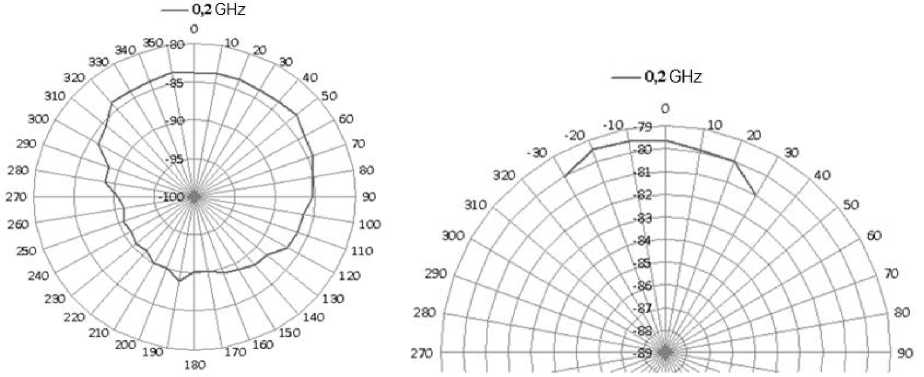
The radiation patterns of the studied 0,2 GHz band antenna are shown in fig. 3.
a
b
Рис. 3. Диаграммы направленности антенны на частоте 0,2 ГГц: а – горизонтальная плоскость; б – вертикальная плоскость
Fig. 3. Antenna pattern at 0,2 GHz: a – horizontal plane; b – vertical plane
As a result of measuring the width of the bottom of the TBNG emitting antennas in the frequency ranges of 0,2 – 6,0 GHz, the direction patterns were constructed for each antenna at three frequencies (lower, central and upper). The width of the bottom for each antenna is 120 ° ± 10 ° in the horizontal plane and 60 ° for the vertical plane at the level of minus 3 dB.
Next, the measurements of the depth of the TBNG power adjustment were performed. The TBNG being studied was installed on a turntable in the working position. To measure the depth of power adjustment, the measuring equipment is connected according to the scheme shown in fig. 4 using passthrough attenuators.
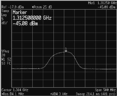
The maximum signal level is measured when the generator is switched on, and then the power output of the generator is reduced by 1 dB and the signal levels are measured again. The above measurements are carried out in increments of 1 dB at least 20 times. The measurement of the maximum signal and attenuated signal levels for the entire working barrage band of each generator is performed at least three times. Then the average value is calculated. The depth of power adjustment was 0-20 dB.
Anechoic chamber
Рис. 4. Схема проведения измерений:
1 – исследуемый генератор; 2 – измерительный приемник
Fig. 4. Measurement scheme:
1 – generator being studied; 2 – measuring receiver
The level of adjustment of the maximum signal level is calculated using the following formula:
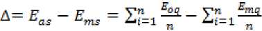
,
where E as is the level of the attenuated signal when the generator is turned on; E ms is the level of the maximum signal when the generator is turned on; n is the number of measurements.
The numerical values of the voltage measurements of the received signal for the level of adjustment of the generator from 0-20 dB, in the frequency range of 0,2 - 1,5 GHz, are given in Table 4.
The values of the voltage measurements of the received signal
Table 4
|
The TBNG being studied |
E as1 , dBm |
E as2 , dBm |
E as3 , dBm |
E as , dBm |
ms1 , dBm |
ms2 , dBm |
ms3 , dBm |
ms , dBm |
Adjustment Δ , dB |
|
Range 0,2 - 1,5 character № 1 |
-45,1 |
-45,6 |
-44,5 |
-45,1 |
-25,1 |
-25,5 |
-24,3 |
-25,0 |
20 |
|
-44,0 |
-44,0 |
-43,5 |
-43,8 |
-25,1 |
-25,5 |
-24,3 |
-25,0 |
19 |
|
|
-43,1 |
-43,1 |
-42,5 |
-42,9 |
-25,1 |
-25,5 |
-24,3 |
-25,0 |
18 |
|
|
-42,0 |
-42,2 |
-41,9 |
-42,0 |
-25,1 |
-25,5 |
-24,3 |
-25,0 |
17 |
|
|
-41,0 |
-41,0 |
-40,7 |
-40,9 |
-25,1 |
-25,5 |
-24,3 |
-25,0 |
16 |
|
|
-40 |
-40,8 |
-39,9 |
-40,2 |
-25,1 |
-25,5 |
-24,3 |
-25,0 |
15 |
|
|
-39,1 |
-40,0 |
-38,4 |
-39,2 |
-25,1 |
-25,5 |
-24,3 |
-25,0 |
14 |
|
|
-38,1 |
-38,9 |
-37,5 |
-38,2 |
-25,1 |
-25,5 |
-24,3 |
-25,0 |
13 |
|
|
-37,1 |
-38,0 |
-37,0 |
-37,4 |
-25,1 |
-25,5 |
-24,3 |
-25,0 |
12 |
|
|
-36,0 |
-36,5 |
-35,6 |
-36,0 |
-25,1 |
-25,5 |
-24,3 |
-25,0 |
11 |
|
|
-34,9 |
-35,7 |
-33,9 |
-34,8 |
-25,1 |
-25,5 |
-24,3 |
-25,0 |
10 |
|
|
-34,0 |
-34,2 |
-34,0 |
-34,1 |
-25,1 |
-25,5 |
-24,3 |
-25,0 |
9 |
|
|
-33,0 |
-33,4 |
-32,6 |
-33,0 |
-25,1 |
-25,5 |
-24,3 |
-25,0 |
8 |
|
|
-32,0 |
-32,1 |
-31,1 |
-31,7 |
-25,1 |
-25,5 |
-24,3 |
-25,0 |
7 |
|
|
-31,0 |
-31,6 |
-30,3 |
-31,0 |
-25,1 |
-25,5 |
-24,3 |
-25,0 |
6 |
|
|
-30,1 |
-30,6 |
-29,6 |
-30,1 |
-25,1 |
-25,5 |
-24,3 |
-25,0 |
5 |
|
|
-29,1 |
-29,5 |
-28,6 |
-29,1 |
-25,1 |
-25,5 |
-24,3 |
-25,0 |
4 |
|
|
-28,0 |
-28,3 |
-27,5 |
-27,9 |
-25,1 |
-25,5 |
-24,3 |
-25,0 |
3 |
|
|
-27,1 |
-27,9 |
-26,4 |
-27,1 |
-25,1 |
-25,5 |
-24,3 |
-25,0 |
2 |
|
|
-26,0 |
-26,8 |
-26,0 |
-26,3 |
-25,1 |
-25,5 |
-24,3 |
-25,0 |
1 |
|
|
-25,1 |
-25,5 |
-24,3 |
-25,0 |
-25,1 |
-25,5 |
-24,3 |
-25,0 |
0 |
* Note - the values of the maximum signal strength in tab. 4 are rounded to integers.
To visualize the process, fig. 5 shows a spectrogram of the depth of power adjustment, which is based on the results of voltage measurements presented in Table 4, for a maximum signal level of 0 dB and 20 dB.
а
б
Рис. 5. Спектрограмма глубины регулировки мощности: а – 0 дБ; б – 20 дБ
Fig. 5. Power adjustment depth spectrogram: a – 0 dB; b – 20 dB
According to this principle, the measurements of the depth of adjustment of the power of the TBNG in the range of 1,5 – 6,0 in an anechoic shielded chamber were carried out, for each generator in the working band of the barrier at the level of at least 20 dB with a step of ± 1 dB.
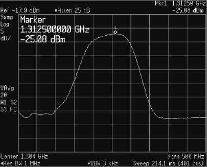
The scheme for measuring the overlap range of the TBNG is similar to fig. 4. For each generator, three measurements were carried out for the entire working barrage strip of each generator. The results obtained during the measurements of the overlap range of the TBNG from 0,2 – 1,5 are shown in fig. 6.
Рис. 6. Диапазон перекрытия ПДГШ
Fig. 6. The overlap range of the TBNG
It can be seen from fig. 6 that the overlap range of the generator character № 1 is a range from 0,2 GHz to 1,5 GHz with a small (≈ 3 dB) decrease in the levels of generated noise at the boundaries of the range. Similarly, the measurements were carried out for all other characters № 2, 3, 4.
A set of control NSM can have n number of narrowband filters with a given bandwidth and a selected readjustment discreteness. In this case, fig. 7 shows the range of sequential inclusion of three adjacent bandpass filters, which shows that the overlap band of each filter is superimposed on the previous frequency range, thereby allowing you to adjust the width of the overlapping spectrum.
Next, the measurements of the working band of the barrier for the first band NG were performed. The TBNG being studied was installed on the turntable in the working position, the measuring equipment was connected according to the scheme shown in fig. 4. The working barrage band for the generators with characters № 1, 2, 3 must be at least 100 MHz and at least 200 MHz for the character № 4.
The results obtained during the measurements of the working band of the barrier of the TBNG for the first filter relative to its maximum level of minus 3 dB are shown in fig. 8.
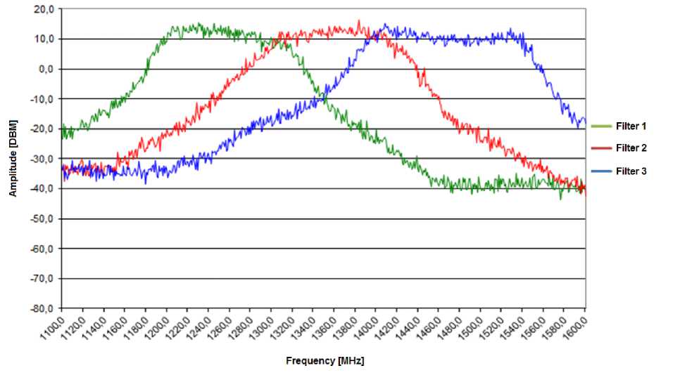
Рис. 7. Диапазон перекрытия полосовых фильтров
Fig. 7. Bandpass filter overlap range
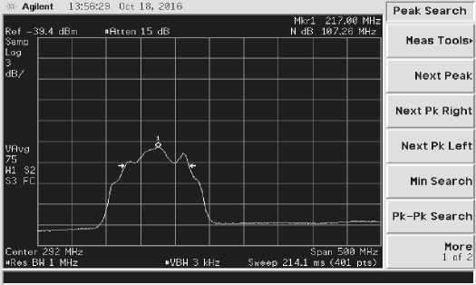
Рис. 8. Рабочая полоса заграждения
Fig. 8. Working barrage strip
It can be seen from the analyzer readings that the barrier band for this filter is 107,26 MHz, which meets the specified requirements. The averaged measurement results for all the filters used in the TBNG are summarized in Table 5.
Averaged measurement results of applied filters
Table 5
|
№ of a character |
Overlap range, GHz |
The working band of the barrier, MHz |
|
1 |
0,2 to 1,5 |
106,2 |
|
2 |
1,5 to 2,5 |
103,0 |
|
3 |
2,5 to 4,0 |
104,1 |
|
4 |
4,0 to 6,0 |
224,5 |
According to the measurement results given in Table 5, all the filters used in the TBNG for the characters № 1, 2, 3 in the range of 0,2 – 4,0 GHz meet the requirements for the width of the working band of the barrier and are at least 100 MHz. The filters used in the TBNG with the character № 4 in the range of 4,0 – 6,0 GHz meet the requirements for the width of the working band of the barrier and are at least 200 MHz.
Conclusion
The structure of the TBNG for spatial noise reduction of computer equipment has been developed. It is characterized by an extended frequency range from 200 MHz to 6 GHz, adjustable integrated noise power at the input of the emitting antenna of at least 3 Watts, an improved energy-saving mode of operation, which allows its use as an autonomous protection device. It allows to adjust the radiation power for each band of the emitted signal up to 20 dB in ± 1 dB increments. It has the degree of freedom of the antenna in the horizontal and vertical planes ± 30 ° and the width of the radiation pattern in the horizontal plane up to 120 ± 10 ° at the level of minus 3 dB.
The noise signal generator being considered in the work, where the formation of a noise signal is carried out using amplitude modulation, can be used in multichannel noise signal generators as a source of a noise signal with a frequency-tunable spectrum width depending on the central frequency of the modulating signal based on the use of the noise source modules with bandpass filters. This makes it possible to eliminate the failure of the amplitudes of the spectral components of the noise signal in a wide frequency range, which contributes to obtaining a uniform amplitude of the spectrum of the noise signal at the output of the device when performing the operation of changing the width of the spectrum of the noise signal.
References Development of tunable band noise genera-tors
- Men’shakov Yu. K. Teoreticheskie osnovy tekhnicheskikh razvedok [Theoretical foundations of technical intelligence]. Moscow, IPTs Maska Publ., 2017, 640 p.
- Men’shakov Yu. K. Zashchita ob”ektov i informatsii ot tekhnicheskikh sredstv razvedki [Protec-tion of objects and information from technical means of intelligence]. Moscow, Izd. RGGU Publ., 2002. 399 с.
- Men’shakov Yu. K. Osnovy zashchity ot tekhnicheskikh razvedok [Fundamentals of protection from technical intelligence]. Izd. MGTU im. N. E. Baumana Publ., 2011. 478 с.
- Ryzhenko S.V. [On the issue of side electromagnetic radiation of modern computer interfaces]. Aktual’nye problemy obespecheniya informatsionnoy bezopasnosti. 2017, P. 170–176 (In Russ.).
- Kupriyanov A. I. Radioelektronnaya bor’ba [Radio-electronic struggle]. Moscow: Vuzovskaya kniga Publ., 2013, 360 p.
- Khorev A. A. Teoreticheskie osnovy otsenki vozmozhnostey tekhnicheskikh sredstv razvedki [Theoretical foundations for assessing the capabilities of technical means of reconnaissance]. Moscow, MO RF Publ., 2000. 255 с.
- Avdeev V. B., Anishchenko A. V. [Comparative evaluation of methodological approaches to the calculation of the signal / noise ratio in the problems of monitoring the security of information from leakage due to spurious electromagnetic radiation] Spetsial'naya tekhnika. 2016, No. 1, P. 54–63 (In Russ.).
- Petrakov A. V. Osnovy prakticheskoy zashchity informatsii [Fundamentals of practical infor-mation security]. Moscow, Radio i svyaz’ Publ., 2000, 361 с.
- Khorev A. A. Tekhnicheskaya zashchita informatsii [Technical protection of information]. Vol. 1. Moscow, NPTs Analitika, 2008, 436 p.
- Hong J.-S., Lancaster M. J. Microstrip Filters for RF/Microwave Applications. John Wiley & Sons, 2001, 473 p.
- Artes H., Matz G., Hlawatsch F. Linear time–varying channels. Tech. rep., Institute of Com-munications and Radio-Frequency Engineering, Vienna University of Technology, 1999.
- Barsukov V. S. Bezopasnost’: tekhnologii, sredstva, uslugi [Security: technologies, tools, ser-vices]. Moscow, KUDITS OBRAZ Publ., 2001, 496 p.
- Bezrukov V. A., Ivanov V. P., Kalashnikov B. C., Lebedev M. N. Ustroystvo radiomaskirovki [Device of radio deception]. Patent RU No. 2170493 Russian Federation, IPC Н04К 3/00; declared 15.05.2000; publ. 10.07.2001, BI No. 19.
- Sistema dlya zashchity ot utechki informatsii po kanalam PEMIN “Grom–ZI–4B” [System for protection against information leakage through SERaI channels. ”Grom-ZI-4B”]. Available at: https://pro-spec.ru/catalog/generatory-shuma/sistema-dlya-zashchity-ot-utechki-informatsiipo-kanalam-pemin-grom-zi-4b (accessed: 24 November 2020).
- SEL SP–21 Barrikada generator prostranstvennogo zashumleniya [SEL SP–21 Barricada spa-tial noise generator]. Available at: http://www.spectr-sks.ru/product/8535 (accessed: 26 November 2021).
