∆DHT-Zip: A Delta-difference Hybrid Tree Coding Scheme for End-to-end Packet Compression Framework in Network-on-Chips

Author: T. Pullaiah, K. Manjunathachari, B.L. Malleswari
Journal: International Journal of Computer Network and Information Security @ijcnis
Article in issue: 2 vol.17, 2025.
Free access
Due to the maximal transistor count, Multi-Processor System-on-Chip (MPSoC) delivers more performance than uniprocessor systems. Network on Chip (NoC) in MPSoC provides scalable connectivity compared to traditional bus-based interconnects. Still, NoC designs significantly impact MPSoC design as it increases power consumption and network latency. A solution to this problem is packet compression which minimizes the data redundancy within NoC packets and reduces the overall power consumption of the whole network by minimizing a data packet size. Latency and overhead of compressor and decompressor require more memory access time, even though the packet compression is good for the improved performance of NoC. So, this problem demands a simple and lightweight compression method like delta compression. Consequently, this research proposes a new delta-difference Hybrid Tree coding (∆DHT-Zip) to de/compress the data packet in the NoC framework. In this compression approach, the Delta encoding, Huffman encoding and DNA tree (deoxyribonucleic acid) coding are hybridized to perform the data packet de/compression approach. Moreover, a time series approach named Run Length Encoding (RLE) is used to compress the metadata obtained from both the encoding and decoding processes. This research produces decreased packet loss and significant power savings by using the proposed ∆DHT-Zip method. The simulation results show that the proposed ∆DHT-Zip algorithm minimizes packet latency and outperforms existing data compression approaches with a mean Compression Ratio (CR) of 1.2%, which is 79.06% greater than the existing Flitzip algorithm.
NoC Framework, Data Packet De/compression, Delta Difference, Time Series Approach, Huffman Tree Encoding, DNA Tree
Short address: https://sciup.org/15019787
IDR: 15019787 | DOI: 10.5815/ijcnis.2025.02.02
Text of the scientific article ∆DHT-Zip: A Delta-difference Hybrid Tree Coding Scheme for End-to-end Packet Compression Framework in Network-on-Chips
In recent years, large caches and cores have taken an essential part in chip multi-processors (CMP) [1]. CMPs have recently become more widespread in high performance and embedded systems. CMP outperforms single-core solutions in Thread-Level Parallelism (TLP) by merging multi-cores on a single device [2]. Then, with the full leverage of the computing capabilities of multi-cores, a big shared on-chip cache is preferable to small private caches [3]. On the other hand, a standard shared-memory multi-core arrangement in a single bus as a communication backbone has restricted bandwidth [4]. Due to frequent packet transfer, the bus is frequently overburdened and becomes a performance bottleneck. Therefore, an enhanced version of NoC replaces the traditional NoC to provide a scalable and effective interface for memory and cache access [5].
The NoCs interconnect connects every component point to point and can offer a high-performance network that can accommodate various needs for communication between chip cores [6]. However, NoCs face several constraints on high network power dissipation and long end-to-end communication latency [7]. The high-performance NoC architecture can be designed based on aspects such as topology, flow control, routing algorithm and routing architecture. First, the topology of the NoC architectures has to be decided to connect the units on a chip like a cache, memory and processor [8]. In a 2D or 3D network, the topology could be a butterfly, a torus, a mesh, etc. [9]. This tends to apply an optimal routing algorithm, which can be deterministic, adaptive, or oblivious [10]. Deterministic routing is the most commonly used routing technique, as it may considerably reduce hardware complexity [11]. In contrast, adaptive routing and oblivious routing typically offer better performance at the expense of increased hardware complexity [12]. The flow control includes the NoC resource allocation schemes and (Quality of Service) QoS. But these aspects tend to increase the design complexity, insignificant performance and high-power dissipation [13].
An alternative method of NoC architecture is data compression. Source coding refers to reducing data packets to fewer bits before they are stored or transferred [14]. Data compression is used in hardware design to improve system performance and lower power consumption [15]. There are two types of compression available: cache compression [16] and packet compression [17]. In this, cache compression increases the capacity of the cache by cramming more data blocks into the available area [18]. Several cache compression techniques, such as Zero-Content Augmented (ZAC) cache design, value-centric mechanism-based compression technique [19], Base-Delta-Immediate (B1I) [20], etc., are being developed. But these cache compression technique needs a fundamental change to support different sizes of cache lines [21]. As a result, the compression techniques may not be applicable in a SOC implementation that contains multiple non-modifiable hard IP blocks from different vendors. In the case of packet compression, the size is reduced by using data redundancy to reduce network performance. Thus, this reduction in packet sizes decreases the dynamic power dissipation, network traffic and wastage of link bandwidth. Although packet compression improves NoC performance, many constraints in the compressor and decompressor increase average memory access time [22]. Hence, lightweight and simple compression, such as Delta compression, can be used to overcome the limitations of existing compression techniques [23].
Delta compression delivers data as differences rather than the entire data set [24]. It is often employed in video compression codecs and the networking sector to dramatically reduce frame size and Internet traffic. Furthermore, HTTP servers can provide updated Web pages based on version differences. A low dynamic range is displayed for cache/memory data based on several reasons: same data values, array representation of a large piece of data, a change in memory address or register by programs etc., thereby indicating the efficiency of data compression. Hence, delta compression is considered a prominent technique to compress cache/memory via on-chip interconnects [25]. So, this work mainly aims to develop a new compression framework for NoC. Major contributions of this research are listed as follows:
• To determines a unique trade-off between the compression rate carried out by the compressing method and the speed of compression/decompression approaches.
• To compress the most frequently occurring delta-difference by integrating the Minimum Variance Huffman and DNA coding.
• To reduce the overhead of the Huffman table by compressing it with a Time Series Compression approach.
• To improve the security of NoC-connected SoCs by integrating DNA encoding with Huffman encoding.
• To validate the proposed compressor unit’s performance in terms of compression ratio, latency, power
2. Related Works
consumption, and area.
The remainder of this research report is organized as follows: Section 2 labels recent literature related to this research, Section 3 thoroughly explains the proposed methodology and its working procedure, Section 4 displays the simulations and result in analysis of the proposed methodology, and Section 5 describes the conclusion and future enhancements of the proposed methodology.
Several reviews based on the delta compression framework for NoCs are given as follows:
In massive parallel multi-core systems, there is a severe constraint on large memory bandwidth and power consumption. As a result, approximation computing is regarded as the best approach for large computations while overcoming accuracy constraints. Rahul et al. [26] presented a data approximation context for NoC architectures (APPROX-NoC) that would allow approximate matching of data patterns over a controlled value range in order to compress data patterns and reduce data flow across the chip.
Current multi-core systems consume more time and power when data is transmitted from on-chip interconnects. The data-intensive applications like pattern recognition and machine learning create the worst situation on these systems. Yuechen and Ahmed [27] proposed an approximation communication for NoCs. Here, an approximate communication context and an application error tolerance are developed by including a data approximation mechanism and a quality control technique to decrease NoC’s power consumption and latency on the network. During transmission, this quality control approach detects error-resilient variables that can be approximated and establishes their error thresholds based on the application’s quality requirements. Data approximation comes up with lightweight lossy compression that decreases the packet size and also helps reduce NoC traffic while maintaining application quality standards.
Similarly, Md Farhadur and Paul [28] developed an approximation communication for NoCs to reduce power consumption. Preliminary results are used to increase the energy efficiency and performance of NoCs in this case. Various approximate communication techniques are provided to minimize data transfer in NoC. Finally, tentative solutions are provided to overcome the hardware and software complexity in the approximation approach of NoC.
An effective on-chip interconnection is made possible by the NoC and a router-based packet switching network. Existing studies have demonstrated that NoC’s architecture and performance influence the system’s overall performance, particularly for highly parallel workloads. Here, Xingyu and Tushar [29] developed FlitReduce to improve the data transmission efficiency over NoC. FlitReduce uses compressors and decompressors at the endpoints of the NoC to minimize the amount of total memory traffic. Therefore, communication congestion enhances the NoC’s performance with minimal impact on the network’s other components.
Data-intensive and communication-focused applications exert a large demand on the underlying network by sending packets containing blocks from various cache hierarchies to the requesting core. This will happen when a cache miss occurs. Increased packet transmission latency distracts the system as a whole. The rise in data packets that follow the cores’ relevance raises the NoC’s dynamic energy consumption. Therefore, Dipika and John [30] created FlitZip to compress network packets and reduce on-chip traffic. As a result, compressed packets move with less bandwidth, conserving network resources. This would help in decreasing the network’s power consumption.
The performance of parallel applications on a many-core computer system is strongly impacted by communication latency, which is a key consideration for NoC architecture. Naoya et al. [31] proposed an on-chip router which performs switch arbitration first, then decompresses the contents of incoming packets to decrease communication latency. As a result, the compression router does not incur any latency penalties during the compression process but shortens the packets to reduce the latency of network injection and ejection.
The NoC performance can be improved using the packet compression approach. However, the average memory access time has been increased due to the overhead and delay introduced by the compressor/decompressor modules. This issue can be tackled by introducing naïve and light weighted compression methods. The delta encoding methods are usually utilized for ease, less complexity, lower delay and power consumption. But, the compressed packet generated by the delta encoding methods may include highly repetitive difference values. The Huffman method is mostly used to compress the repeated values. However, the Huffman algorithm should know the probability distribution for building a code tree and assigning code words to the different values. As a result, it increases the metadata for each packet, thereby restricting the compression rate. NoC structure also needs secured data processing and routing in multi-core SoC. But the secured network routing cannot be provided to the physical access network easily. The simplest way to improve the security of NoC-connected SoCs is the integration of Cryptography along with packet compression. These points motivate us to develop a new compression method by considering the best properties of Delta encoding, Huffman and DNA encoding.
3. Proposed Methodology with NoC Architecture
Before explaining the working procedure of the ∆DHT-Zip compression technique, this section briefly explains the architecture of NoC used in this research. There are 16 cores created for 4x4 NoC mesh topology in which the cores are arranged as tiles, as well as every single tile contains a core, part of a shared L2 cache (named as a bank) and a private L1 cache. Network Interface (NI) connects every single tile to the NoC, organized as a 2D mesh topology. NI use an inject and eject queue to transfer and receive cache blocks from the CPU. A request packet can be destined to the L2 cache, producing the miss in the L1 cache. So, based on the request, the reply packet is forwarded from the bank to the requesting core. Generally, NoC traffic is generated by the routers, links, requests and reply packets of the NoC framework. Only one head flit in the NoC makes request packets, and reply packets are separated into head, body and tail flit. In other words, the head flit carries the data packet and the body’s control information, whereas the tail flit contains the cache block contents.
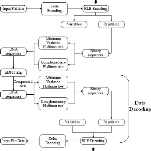
Fig. 1 depicts the proposed NoC architecture, which includes the input port buffers Switch Allocator (SA), Virtual Channel (VC), Virtual channel allocator (VA), Virtual Channels (VCs), and Route Computation (RC) unit. The RC verifies that the data packet has reached the destination output port, while the VA controls the number of VC in the downstream router. SA handles port congestion and assigns the output port through which flits leave a router, and links in the NoC structure carry flits from one router to another [32]. Fig. 2 below illustrates the workflow design for the proposed technique.
In this research, the ∆DHT-Zip scheme is proposed to compress the data packets in NoC. Initially, a 16-core NoC based multi-processor is developed by considering 4x4 Mesh topology. A generic NoC router is intended to transport data between source and destination using NI to packetize or depackage the data. NI employs the planned DHT-Zip compression technology. Initially, the input packets are encoded using ∆ encoding. This ∆ encoding scheme determines the difference value between two consecutive values to compress the packets. The RLE method is used to find the occurrences of the resultant difference values, which are highly repetitive. Hence, the most frequently occurred ∆ value should be compressed to obtain the shortest code word. To do this, a DNA tree is constructed utilizing Minimum Variance Huffman coding after determining the binary equivalent of the ∆ values. After that, this DNA tree is used as a codebook for assigning the code words with fewer bits to the values that occur more regularly. However, the Huffman table adds more metadata and restricts the compression ratio. To tackle this issue, the time Series Compression approach, named RLE, performs both the encoding and decoding process.
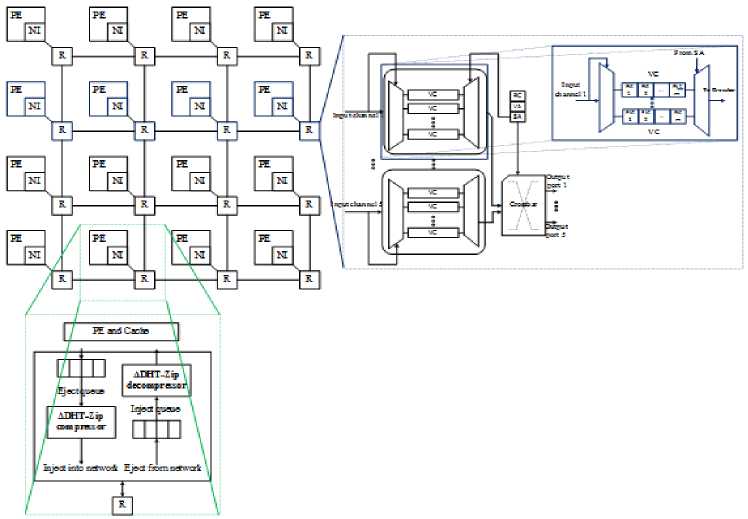
Fig.1. Proposed NoC architecture
Time series compression
Fig.2. Workflow diagram of the proposed ∆DHT-Zip technique
Time series compression
-
3.1. Data Packet Format of NoC
The general format of the data packet presented in the NoC is displayed in Fig. 3. In NoC, each data packet has a header, body, and tail flit, with the header flit controlling the packet’s control data. The contents of a cache block are delivered in the body and tail flits; n flits with kbytes are presented in this data packet. In this research, the size of flit 1 is considered 152-bit as it is taken to perform the encoding and decoding process because creating a DNA tree requires more data. The link bandwidth determines the size of each flit, and this system requires 152 bits per cycle. The link bandwidth between two routers can be specified depending on the packet sizes. When the packet size is large, it is possible to maintain a wide link width. Link bandwidth can potentially impact NoC design performance. Increasing the link bandwidth decreases the network power of a mesh design. This is because a drop in link bandwidth might increase network congestion, hence increasing the consumption of dynamic buffer, crossbar, and link power. Alternatively, a mesh topology’s increased link capacity can alleviate congestion and minimize dynamic power.
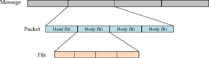
Fig.3. The general format of a data packet in NoC
In this work, 3 different random flits with different sizes are considered to perform the compression and decompression process. The header flit is 180 bits in size, flit 1 is 152 bits, and the remaining two are 16 bits in size. The data packet utilized in this research is displayed in Fig. 4. This header flit comprises the packet number (PID), source tile (Src), VC number wherein the input flit is stored, Message Type (MTyp): REQ/REP/coherence packets, destination tile (Dst), Flit type (FTyp): head/body/tail, and missed memory address (M — ADR). This header flit has 128 unused Least Significant Bits, and the proposed ∆ DHT-Zip compressor uses these unused locations for storing metadata, hence increasing the compression ratio [33].
180-bit 152-bit 16-bit 16-bit
Header flit Flit 1= 09 15 19 23 25 27 37 47 57 67 70 72 74 76 78 80 85 90 91 Flit 2= CC CC Flit 3= 11 11
ID FT[1:0] VC[1:0] Src[5:0] Dest[1:0] MT[1:0] Mem Address[31:0] Unused[127:0]
<-M---M---M---M----M----M--------M------►
2-bit 2-bit 2-bit 6-bit 6-bit 2-bit 32-bit 128-bit
Fig.4. Format of a data packet used in this research
-
3.2. ∆DHT-Zip De/Compressor
-
3.3. DNA Tree with Minimum Variance Huffman Coding
To make the input data more convergent, the delta encoding technique is performed as the pre-processing step, increasing the similarity of input data. Secondly, the RLE technique is applied to overcome the variables that have more than two occurrences. Delta encoding is a lossless compression algorithm, also known as relative encoding, that is applied to find out the difference between the two consecutive numbers of the input data and the given below expression is used to find the difference between two numbers, a = zt — z-
After finding the difference, the resultant difference value is mentioned as a variable. The time series compression method known as RLE is used to replace the repeated variables in which the number of occurrences is defined as repetition values [34]. Then, the repetition values are given as the input to the DNA tree explained in the upcoming subsection.
The DNA nucleotide sequences that preserve the constraints in this method are developed using a minimum variance binary Huffman tree [35] process. In contrast, the Huffman algorithm employs Huffman codes, classified as a type of prefix code. It creates the code with a minimum average length for all available source input, so it is named a compact code. The variance 62 of a Huffman tree containing?! leaf nodes that correspond to each symbol of the source, the probability of their occurrenceprt and their distance from the root lent . So, based on that, the variance is calculated using S2 = X n= 1P r t (l ent - S')2 . Each codeword’s average length is given as Sand is given byS = X n= 1P r t lent . Minimum variance Huffman tree is defined as having minimum variance out of all possible Huffman trees from a source.
Algorithm 1: DNA tree creation from Binary value
Input: Binary value of repetition data
Output: DNA trees TR, complementary tree TR , Code words CW and CW
Begin
Get the input binary data as a block of 8-bit length (Blen)
Generate a minimum variance Huffman tree TR by taking every block as symbol for every edge (a,b) £ TRdo if b == a. left then if ais at odd distance from TR. rootthen
(a,b) = A else
(a,b) = G else if a is at an even distance from TR. tree then
(a,b) = T else
(a,b) = C end if end for
Generate TR' = TR for every edge (a, b) £ TR do if (a,b) == Athen
(a, b) == G else if (a,b) == G then
(a,b) = A else if (a, b) == Cthen
(a,b) = T else if (a, b) == Athen
(a,b) = C end for
Generate code words CW and CW from trees TR and TR respectively.
Return TR, TR' , CWand CW'
Algorithm 2: DNA tree encoding
Input: Binary value of repetition data, and code word book CWand CW
Output: DNA sequences
Take current codeword book = CW for every block of 8-bit length (Blen) do cw = codeword from current codeword book for first symbol if length(cw) == odd then if current codeword book == CW then current codeword book = CW'
else current codeword book = CW endif
Add CW to DNA sequence endfor
Return DNA sequences
The algorithm that requires to construct the Huffman code is described in this section. Initially, the occurrence probability is determined to sort out all the available source symbols. Symbols having a low probability are placed further away from the root. After that, the encoded symbols are determined by analyzing the path from the root to the node. After data compression into a DNA sequence, the most important step is identifying the input data’s binary equivalent. After binary data construction, the DNA tree is developed for encoding and decoding. Then, the division is performed over the binary data to obtain the non-overlapping blocks having a length(Bien). Every divided block is used as a source symbol in the minimum-variance construction of the Huffman tree TR. The edges of the left child nodes are labelled A and G, whereas the nodes corresponding to the right ones are labelled T and C. To develop a complementary treeTR ' , the A is replaced with G, G with A, T with C, and C with T. Then, from the trees TR andTR ' , the codebooks CW and CW' are constructed, and the procedure for codebook generation is shown in algorithm 1.
In the encoding process, input data is read block by block, starting from a codebookCW. The DNA sequences are attained from the codebookCW. If the sequence length is odd, the complement codeword bookCW' is utilized to preserve run length. The same DNA tree is used in the encoding process, where the sequence is read character by character and traverses from the root to other leaf nodes. When a leaf node is met, its value contains the decoded block information. Similarly, if the path length from the root to the leaf node is odd, the decoding method is carried out using the complementary tree. The given algorithms 2 and 3 present both encoding and decoding algorithms, respectively.
Algorithm 3: DNA tree Decoding
Input: DNA sequences, and DNA trees TR and TR
Output: Symbols
Take current tree = TR node = currenttreeroot for every nucleotide n in DNA tree do node = Traverse (node, n) if node is a leaf node, then
Add the symbol related with the node to binary value if distance from currenttreerootto node is odd then if currenttree = TRthen currenttree = TR' else currenttree = TR endif endif endfor
Return Symbols
-
3.4. Illustration for the Proposed ∆DHT-Zip De/Compressor
The illustration of the proposed ∆DHT-Zip De/compressor is explained in this subsection. In this illustration, three random flits are considered in which Flit 1 contains 152-bit data purposely taken for the encoding and decoding process. Because the tree creation needs more numbers to perform the compression process, the other two flits contain the same data, so it doesn’t require the compression procedure. Initially, Delta encoding is performed to the input sequence, which calculates the difference between the two consecutive numbers and gets the results as variables. Also, in Delta encoding, the first input number is written as it is and included in the variables list. Then RLE algorithm is performed to find the repetition count of that variables. The illustration of this Delta encoding with the RLE process is given in below.
152-bit
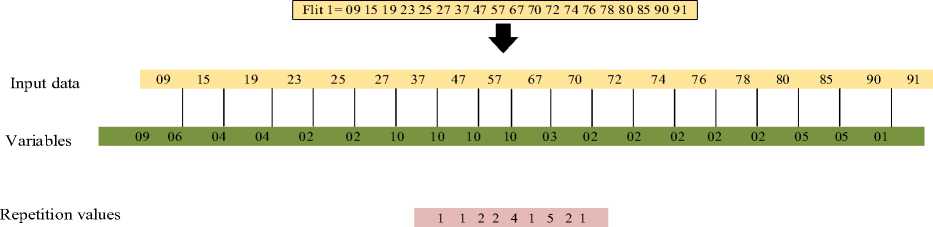
72 bit (9 bytes)
Fig.5. Illustration of delta encoding with RLE algorithm
After performing the RLE process, the binary representation of the repetition count is taken as the input for the DNA tree. So, in the next step, the repetition value is converted into a non-overlapping block of the 8-bit binary value. The given below Fig. 6 displays the original input value and its binary form.
Input to DNA tree 1 1 2 2 4 1 5 2 1
Convert to 8-bit binary 00000001 000000001 00000010 00000010 00000100 00000001 00000101 000000010 000000001
Fig.6. Input to the DNA tree and its corresponding binary value
Each block is considered a source symbol to generate a minimum-variance Huffman treeTR. In this example, the repetition values are 1, 1, 2, 2, 4, 1, 5, 2, and 1 in which the occurrence of value 1 is 4 times, value 2 is 3 times, value 4 is one-time, and 5 is only one time. From these occurrences, the symbols are assigned in which S 1 is assigned for value 1, S 2 is assigned for value 2, S 3 is assigned for value 4 and S4 is assigned for value 5. Moreover, the probability is calculated for each symbol in which the probability of S 1 is 4/9, probability of S2 is 3/9, probability of S 3 is 1/9 and probability of S4 is 1/9. The symbols and their probability representation are listed in table 1.
Table 1. List of symbols and their probability values
|
Symbol (S) |
S i = 00000001 |
S2 = 00000010 |
S3 = 00000100 |
S4 = 00000101 |
|
Probability |
4/9 |
3/9 |
1/9 |
1/9 |
After getting the symbols and the probabilities, the Huffman tree with the least amount of variation is made. Starting with the root node, the edges to the left child nodes are labelled with A and G, and the edges to the right child nodes are labelled with C and T. To create the code word book, the complimentary tree TR ' is created from the minimum variance Huffman treeTR. In this treeTR ' , A is swapped with G, T is swapped with C, G is swapped with A and C is swapped with T, respectively. From these two trees, the codeword book CW and CW ' are generated to perform the encoding process. The given below Fig. 7 displays a minimum variance-Huffman tree TRand its complementary treeTR .
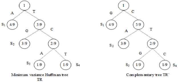
Fig.7. Minimum variance Huffman tree TR and its complementary tree TR
Table 2. Codeword Books and length of codewords
|
Symbols |
Probability |
Codeword books |
Length of code words |
|
|
CW |
CW' |
|||
|
S1 = 00000001 |
4/9 |
A |
G |
1 |
|
S2 = 00000010 |
3/9 |
TG |
CA |
2 |
|
S3 = 00000100 |
1/9 |
TCA |
CTG |
3 |
|
S4 = 00000101 |
1/9 |
TCT |
CTC |
3 |
From Fig. 7, the codeword books are generated from both trees TR andTR ' . The codeword books are generated as per algorithm 1. The encoding process starts after the codeword book is made. The input data is read block by block, starting with the codeword book CW. The DNA sequence is retrieved from this book using algorithm 2. If the leaf node is an odd number of nodes away from the root, the codewords are drawn from both CW and CW ' . If the leaf node is even length from the root, the codewords are taken only from the codework bookCW. The table 2 lists the symbols, codeword books and the corresponding codeword length of the DNA sequence, respectively.
From this table 2, the AGTGTCACTGTCTCTC is obtained as encoding data for the given input value. The encoding data is 128 bits long, and it is stored in the part of the header flit that is not used. The process of encoding data is displayed in Fig. 8. An illustration of ∆DHT-Zip decompression is displayed in Fig. 9.
Input to DNA tree
1 1 2 2 4 1 5 2 1
Convert to 8-bit binary
00000001 000000001 00000010 00000010 00000100 00000001 00000101 000000010 000000001
Encoded DNA sequences
AGTGTCACTGTCTCTC
Fig.8. Encoded DNA sequences
The decoding process also uses the same DNA tree TR and TR ' as well as DNA sequences to obtain the input data. By algorithm 3, the traversal is made from the root to leaf nodes based on the sequences and from the DNA string, these sequences are read character-by-character. Similar to the encoding algorithm, if the path from the root to the leaf node has an odd number of edges, the current tree is replaced with the complementary tree. So, from this decoding algorithm, the symbols are returned, and the decoding symbol representation is given as S 1 S 1 S2 S2 S 3 S 1 S 4 S2 and S 1 . The binary values are obtained from these symbols, which are the repetition counts from the variables. Then RLE method and Delta decoding algorithms combine variables and repetition values to obtain the original input value.
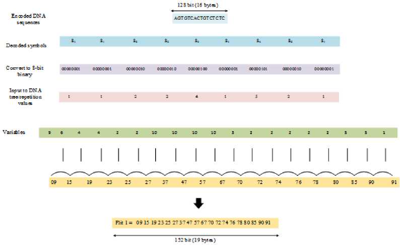
Fig.9. Illustration of ∆DHT-Zip decompression
4. Simulation Results and Analysis
The proposed technique is implemented by considering the 4x4 Mesh structure of the NoC and is simulated using Xilinx ISE tools. The Virtex 7 FPGA family was chosen to synthesize the design with the XC7VX550T chip and FFG1927 package. The synthesis is carried out using the Xilinx XST synthesizer. Furthermore, the proposed technique’s performance is validated using network latency, CR, area, and power consumption. Table 3 lists the system configuration parameters and their values.
Table 3. System configuration
|
Parameter |
Description |
|
Topology |
4×4 Mesh |
|
Core count |
16 |
|
Router |
Generic NoC Router |
|
Router pipeline depth |
5-stage |
|
Routing algorithm |
XY routing |
|
Number of VC |
5 |
|
Buffer depth |
4 |
|
Packet length |
64 Byte |
|
Flit size |
152-bit (19 Bytes) |
-
4.1. Evaluation of Device Utilization and Critical Path Delay
Routers, interconnect channels, NI, compressor and decompressor units are presented in this proposed NoC architecture. Here, sixteen routers are interconnected to form a 4x4 Mesh topology. Simulating the router unit involves integrating RC, VA, SA, Flit Buffers, and Crossbar. Table 4 summarises the device used for the proposed 4x4 Mesh topology. This work uses a total of 2750 slice registers, 4412 slice LUTs, 2736 LUT-FF pairs that are fully utilized, and 677 bonded IOBs.
-
4.2. CR and Network Latency
The critical path delay of each module in the proposed 4*4 Mesh Topology is summarized in Table 5. It is responsible for the logic and routing delays of the critical path. Because the VA, SA, and crossbar switches utilize a complex network of arbitrators or multiplexers, they contribute to a substantial delay. In contrast to the Router unit, the proposed compression unit’s essential route latency is 0 because it lacks a complex network. Thus, it does not influence the critical path of any NoC structure.
Table 4. Summary of device utilization
|
Logic utilization |
Used |
Available |
|
Slice Registers |
2750 |
1224000 |
|
Slice LUTs |
4412 |
612000 |
|
Fully used LUT-FF pairs |
2736 |
4426 |
|
Bonded IOBs |
677 |
900 |
|
BUFG/BUFGCTRL/BUFHCEs |
2 |
32 |
Table 5. Critical path delay analysis for the proposed 4×4 Mesh NoC structure
|
Proposed (∆DHT-Zip) |
||||
|
Unit name |
Logic Delay (ns) |
Wire/routing Delay (ns) |
Total delay (ns) |
|
|
Router |
RC unit |
0.129 |
1.721 |
1.850 |
|
VA |
0.408 |
1.662 |
2.070 |
|
|
SA |
0.129 |
1.875 |
2.004 |
|
|
Flit Buffers |
0.322 |
1.062 |
1.384 |
|
|
Crossbar |
0.086 |
1.450 |
1.536 |
|
|
Total |
1.074 |
7.770 |
8.844 |
|
|
Compression unit |
∆DHT-Zip Compressor |
0.000 |
0.000 |
0.000 |
|
∆DHT-Zip Decompressor |
0.000 |
0.000 |
0.000 |
|
|
Total |
0.000 |
0.000 |
0.000 |
|
|
Total |
1.074 (12 %) |
7.77 (87.86%) |
8.844 |
|
|
Existing (B∆-NIS [36]) |
||||
|
Unit name |
Logic Delay (ns) |
Wire/routing Delay (ns) |
Total delay (ns) |
|
|
Router |
RC unit |
0.129 |
1.474 |
1.603 |
|
VA |
0.404 |
1.401 |
1.805 |
|
|
SA |
0.129 |
1.619 |
1.748 |
|
|
Flit Buffers |
0.043 |
0.822 |
0.865 |
|
|
Crossbar |
0.086 |
1.240 |
1.326 |
|
|
Total |
0.791 |
6.556 |
7.347 |
|
|
Compression unit |
∆DHT-Zip Compressor |
0.494 |
2.617 |
3.111 |
|
∆DHT-Zip Decompressor |
0.000 |
0.339 |
0.339 |
|
|
Total |
0.494 |
2.956 |
3.450 |
|
|
Total |
1.285 (12 %) |
9.512 (88 %) |
10.797 |
|
The graphical representation of table 5 is displayed in Fig. 10. Here, the proposed method is compared against existing method named as B∆-NIS [36] to show the effectiveness of the proposed method is both routing and de/compression process. Likewise, the upcoming subsections explain the performance analysis of different parameters in detail.
Generally, the ratio of compressed flits to original data flit is defined as CR, in which the proposed algorithm is better with a higher ratio. In this research, the CR of the proposed algorithm is compared against state-of-art algorithms like Flitzip [32], No∆ technique [37] and Baseline router without compression methods. Table 6 displays the comparison results of both network latency as well as CR with proposed and existing methodologies. The table shows that the proposed method achieves 1.2% CR, and existing methods like FlitZip [32], No∆ and Baseline router without compression [37] achieve 0.52%, 0.30% and 0 as compression rates. The baseline router and all other compression methods were simulated using 128-bit connection bandwidth, while the proposed method used 152-bit link bandwidth. Due to the significant number of uncompressible flits in a compressed packet, No∆ compression has a relatively low compression rate.
The performance of the proposed algorithm was also evaluated based on network latency, which is the number of clock cycles required to send a data packet from the source port to the destination port. Consequently, packet synthesis at the source PE, packet transmission over the network, and packet extraction at the receiving PE affect network latency. Moreover, network delay is largely controlled by the size of the delivered data packets. The data compression unit at the network interface of the source PE is also incorporated into the process of packet formation. Likewise, the packet extraction operation comprises a data decompression unit at the NI of the receiving PE. ∆DHT-Zip -compressor and decompressor modules demand two and one clock cycles, respectively. The demanding tile receives the header flit before the body flits decompressed at the network interface.
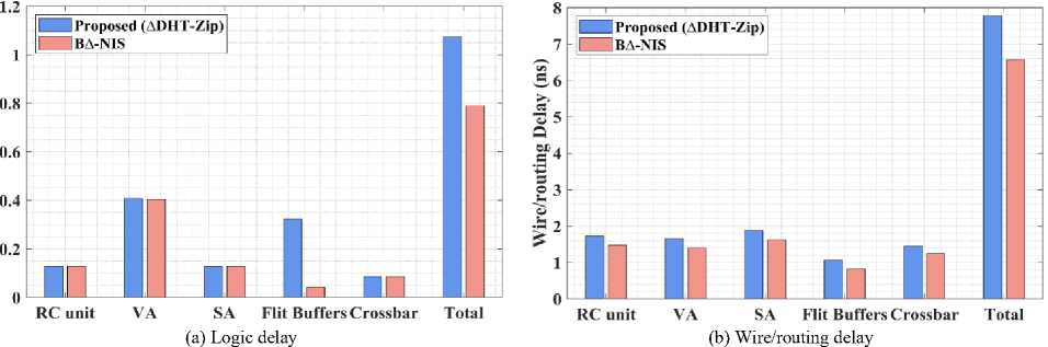
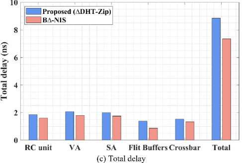
Fig.10. Performance analysis of proposed and existing methods by means of delay
Table 6. Comparison analysis of CR and network latency
|
Techniques |
CR (%) |
Network latency |
|
FlitZip [32] |
0.52 |
0.82ns |
|
B∆-NIS [36] |
0.72 |
0.70 |
|
No∆ [37] |
0.30 |
0.89ns |
|
Baseline router (without compression) [37] |
0 |
1.00ns |
|
Proposed (∆DHT-Zip) |
1.20 |
0.68ns |
Moreover, it reduces decompression latency to a single clock cycle using a single decompressor. Most current systems utilize a single compressor to compress the flits in succession. The compressor module requires numerous clock cycles in these settings to compress the packets. The proposed ∆DHT-Zip employs a single compressor to compress a flit, but subsequent flits containing the same data are not compressed. The performance of network latency was also compared with FlitZip [32], B∆-NIS [36], No∆, and Baseline router [37] without compression technique in which the network latency of proposed ∆DHT-Zip is reduced by 32%, which is 18% and 11% minimum than existing FlitZip and No∆ technique. The graphical representation of table 6 is displayed in Fig. 11.
-
4.3. Power and Area Consumption
The network’s power usage can be classified as either dynamic or static. Each hardware component’s power loss is shown by static power. The intensity of on-chip traffic influences the NoC’s dynamic power performance. When using on-chip communication, the proposed design minimizes packet size. In this research, the proposed ∆DHT-Zip achieves 5.1mW as total power and the existing algorithms like FlitZip [32], B∆-NIS [36] and No∆ [37] achieve 13.75mW, 10.89mW and 36.48mW as total power. The comparison shows that the proposed de/compression algorithm consumes less power for a high compression ratio. Table 7 provides a comparative analysis of power and area use.
Table 7. Comparison analysis of power and area consumption
|
Techniques |
Power |
Area |
|
FlitZip [32] |
13.75mW |
0.0028mm2 |
|
B∆-NIS [36] |
10.89mW |
0.0022 mm2 |
|
No∆ [37] |
36.48mW |
0:006mm2 |
|
Proposed (∆DHT-Zip) |
5.1mW |
0.0024mm2 |
According to this analysis, the No∆ method’s power consumption is extraordinarily high due to the utilization of several de/compression units for different bases and ∆ sizes. However, both the FlitZip and ∆DHT-Zip techniques address this issue. Compared to Flitzip [32], and B∆-NIS [36] the proposed ∆DHT-Zip framework consumes less electricity. As indicated in the network delay study, the proposed solution uses the DNA tree to reduce packet flits while maintaining data quality. As a result, it reduces the proposed framework’s total power usage. Moreover, the proposed de/compression unit consumes 0.0024mm2 as total area, which is considerably less than existing designs except B∆-NIS [36]. The graphical representation of table 7 is displayed in Fig. 12.
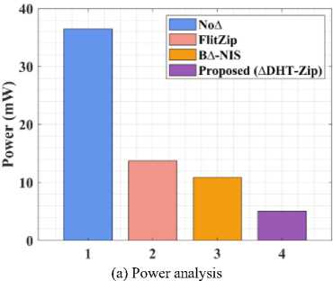
Fig.12. Performance analysis of (a) power and (b) area
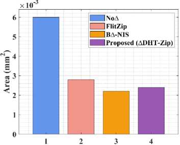
(b) Area analysis
Network Size
Fig.13. Performance analysis or proposed method by varying network size
Table 8. Performance comparison of proposed method for variable configurations
|
Normalized Methods |
Network Size |
Number of cores |
Packet Latency (%) |
|
FlitZip [32] |
2x2 |
4 |
19.47 |
|
4x4 |
16 |
26.86 |
|
|
8x8 |
64 |
28.45 |
|
|
B∆-NIS [36] |
2x2 |
4 |
0.63 |
|
4x4 |
16 |
0.70 |
|
|
8x8 |
64 |
0.95 |
|
|
Baseline [37] |
2x2 |
4 |
43.16 |
|
4x4 |
16 |
51.00 |
|
|
8x8 |
64 |
53.84 |
|
|
No∆ [37] |
2x2 |
4 |
39.12 |
|
4x4 |
16 |
44.94 |
|
|
8x8 |
64 |
46.87 |
|
|
Proposed (∆DHT-Zip) |
2x2 |
4 |
0.52 |
|
4x4 |
16 |
0.68 |
|
|
8x8 |
64 |
0.79 |
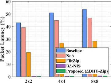
Table 8 compares the Packet Latency of the proposed ∆DHT-Zip framework with B∆-NIS, baseline, FlitZip, and No∆ by changing the NoC sizes to 2x2, 4x4 and 8x8 mesh topology. It shows that the packet latency of proposed ∆DHT-Zip on 8x8, 4x4 and 2x2 configurations performs better than all the existing designs. Here, the flit takes a larger time to reach its destination while increasing the network sizes. Furthermore, the traffic generated by 8x8 NoC is high compared to 4x4 NoC. But, the proposed B∆-NIS outperforms all other methods in terms of Packet Latency. The graphical visualization of table 8 is displayed in Fig. 13.
5. Conclusions
In recent decades, NoC architectures attracted many new fabrication and packaging technologies as it increases the core count of communication architectures. Also, the performance of the communication architecture is enhanced with the help of a well-known technique named data compression. This method has been developed to maximize the effective storage size of multi-core and uni-processor systems. In this research, the ∆DHT-Zip technique is proposed to perform the de/compression process on NoC to reduce the wastage of link bandwidth, network traffic, and power consumption. In particular, it encodes data before packet injection and decodes data prior to ejection in the NI. The architectural specifics of the NoC architecture and NI’s de/compression scheme are examined to determine network latency, CR, critical path delay, area, and power consumption. In comparison to previous approaches, the proposed method achieves 1.2% CR, 5.1mW total power usage, and 0.68ns network latency, all of which are significantly lower than existing methods. The study has emphasized how important data compression methods are to improving NoC-based systems' performance, efficiency, and power consumption. The proposed strategy has shown the effectiveness of several compression algorithms by means of comprehensive research and testing, highlighting their capacity to reduce network congestion and data transmission overheads. The proposed circuit’s hardware emulation will be considered the priority for future enhancement. The hardware simulation should improve network latency in the compression process. In addition to this, optimizing NoC performance will be greatly enhanced by using machine learning techniques for data compression. It will be worthwhile to look into how neural networks and other AI-driven techniques might be used to improve compression efficiency.
