Digital Electro-Hydraulic (DEH) Modeling as a Steam Turbine Governor Control at PLTU Tanjung Enim 3x10MW Using MatLab
 Modeling as a Steam Turbine Governor Control at PLTU Tanjung Enim 3x10MW Using MatLab")
Author: Destra A. Pratama, Dewi P. Sari, Kabul. Abdullah
Journal: International Journal of Information Engineering and Electronic Business @ijieeb
Article in issue: 6 vol.14, 2022.
Free access
Control of the Steam Turbine at PLTU Tanjung Enim 3x10 MW through the use of Digital Electro-Hydraulic (DEH), which plays a critical role in the functioning of the Steam Turbine generated. Because the current control operates solely by manual loading adjustment by raising or reducing the PID percentage from DEH, it is essential to analyze the input parameter values to improve the DEH PID control's sensitivity. The DEH control mechanism of PLTU TE 3x10MW is divided into two modes: Valve Limiter and Load. At PLTU TE 3x10MW, the steam turbine frequently experiences hunting (fluctuations) on the governor control valve, causing the turbine unit to become unstable until shutdown or blackout. The DEH signal response to actuator stroking can generally operate according to the given signal command with a signal density of 1/ΔT = 100,298 Hz and ΔY/ΔT = 781,016 ms. By analyzing the DEH system in the unit and modeling it using Matlab, it is hoped that it will produce a PID control value that can be input into the system based on the return signal from the actuator stroking level and the steam turbine speed at the time of loading, thus enabling the control valve or governor to be more responsive and smoother in responding of Mining load changes, either manually or automatically.
Digital Electro-Hydraulic, Governor, Control Valve, PID, Power Control, Speed Control
Short address: https://sciup.org/15018792
IDR: 15018792 | DOI: 10.5815/ijieeb.2022.06.01
Text of the scientific article Digital Electro-Hydraulic (DEH) Modeling as a Steam Turbine Governor Control at PLTU Tanjung Enim 3x10MW Using MatLab
Published Online on December 8, 2022 by MECS Press
The governor is the piece of machinery responsible for regulating the speed and power of the turbine generator. The governor also regulates the necessary speed and strength to ensure that the steam turbine continues functioning normally. With the changes in the load and the fluctuating character of mine loading, a controller is needed to control the governor so that it can work quickly and stably following the signal from the given Digital Electro-Hydraulic (DEH).
As a result of this load change, the governor is expected to be able to provide fast performance and response so that the system remains in a stable condition. With these needs, a control system is needed to regulate the governor at PLTU Tanjung Enim 3x10MW, currently using DEH as the turbine governor system setting. This DEH signal is added with a PID setting so that the output response from the actuator can respond according to the requested signal or demand signal so that the steam needs to rotate the turbine can operate stably.
The steam turbine used at the PLTU Tanjung Enim 3x10MW is a production from China, namely China Changjiang Energy Corp., with the Condensing Turbine type. In the operation of this steam turbine, the DCS (Distributed Control System) operator experienced several obstacles, including the slow response of the valve opening or control valve when responding to the specified setpoint, so that in controlling the load, dangerous spikes were causing the steam pressure setting in the main boiler to be disturbed. And often blow up steam. The use of DCS not only effectively optimizes the control function and operation level of the power plant but also fulfills the real-time balance of supply and demand then improves the rural power quality and operational efficiency[1].
Blow-up steam occurs when the load spike drops dramatically. PLTU Tanjung Enim 3x10MW is owned by Bukit Asam which is located in Tanjung Enim, Muara Enim Regency, South Sumatra. Indonesia. Only mining loads for PTBA or Captive Power are served by this PLTU while operational. In order to maintain a constant speed for the turbine generator, it is necessary to adjust the rate at which the control valve rotates in response to the varying mine loads. If this is not dealt with appropriately, the resulting damages will be much more severe. This may include power outages or blackouts, damage to rotating equipment, particularly steam turbines, and a significant increase in raw water and chemicals consumption. In the earlier research, the purpose of the DEH modifier on the steam turbine governor was to regulate the frequency variation that was brought on by varying loads (load demand)[2,3].
The mine loading data show that the loading in the mine via the MSS1 and MSS2 feeders is highly unpredictable. It can be seen by looking at the data. Therefore, to adapt the Digital Electro-Hydraulic (DEH) control to the loading, it will be necessary to make adjustments. The steam turbine equipment will be directly affected by fluctuating loading if, while it is operating, it cannot respond to sudden changes, which means that it can cause the unit's failure until the plant a sudden blackout. The problem of hunting of control valves and hunting of speed is faced by many industries in the past years and now they have sufficient knowledge about it but high vibration in the servo motor and servo cylinders is new type for the plant. A vibrationtion level of 80-100 mm/s is a very high vibration and it is sufficient to break any joint of the lube/hydraulic oil and final cause of the turbine trip[4].
In light of these circumstances, performing an analysis of the PID controller tuning is necessary. Specifically, it is essential to tune the PID to determine whether or not the existing controller can still function steadily in response to loading. Understanding the system's characteristics is necessary for designing and analyzing control systems[3]. This final project research proposal will create the DEH Governor control turbine modeling in PLTU TE 3x10MW with primary data that directly affects the turbine control valve performance response using MatLab software. Because of these factors, it is anticipated that the modeling Digital Electro-Hydraulic (DEH) will be able to reset the PID parameter to be more effective in responding to fluctuating mine loads. Adjusting the number of open valves is necessary for one more modeling step, which consists of adjusting the amount of steam that enters the steam turbine to maintain a consistent speed for the turbine rotor[5].
The controller will detect this speed increase, which will then take action to eliminate it. It is achieved by closing the supply valve, reducing the turbine's energy supply. The controller will detect this speed increase, which will then take action to eliminate it and accomplished by closing the supply valve, which reduces the amount of energy supplied to the turbine[6,7]. The controller is responsible for minimizing the error signal, defined as the deviation between the desired signal and the actual signal[8]. The purpose of modeling with this frequency variation is to ensure that the rotational speed of the turbine rotor remains consistent[6,9].
Previous research was carried out by modeling the speed of the turbine because it is common knowledge that the control system for the turbine is a closed loop system. When there is a change in load due to shaft loading or pressure supply variations, the equilibrium between the amount of energy transferred to the turbine from the steam system and the amount of work extracted from the turbine's shaft is disrupted[6]. In general, controlling a steam turbine entails regulating the amount of incoming steam used to rotate the turbine blades, which is the driving force behind the electric generator. The amount of steam admitted is determined by the load placed on the generator, and the speed of the turbine is maintained by the generator's typical rate[10,11].
There is no requirement for the control system model of the entire series of regulators because, at present, the whole of the closed-loop control system adjusts to the power output (load demand) of the generator generated by the turbine. As a result, it is more efficient to control the position of the actuator (control valve) by the demand for power[12,13]. In the actuator system on valve control, hydraulic oil from oil control and lubrication plays an essential role in driving the servo cylinder connected to the actuator (secondary oil) and into the main hydraulic chamber (primary oil). A current command signal (4-20mA) is converted into oil pressure by an I/H converter, which sets the secondary oil pressure[12,5,14].
2. Methodology 2.1 Block Diagram
The block diagram depicts the relationship between the research's input, process, and output (see Fig. 1). Several parameters for the steam turbine and the actuator control are taken in the input section. In addition, the MatLab-Simulink software will be used to carry out the modeling process between the input and output relationships of the steam turbine generator. In addition to reviewing the relevant literature, mathematical modeling employing linear differential equations and Laplace transformations were also carried out. The performance analysis of the governor excitation system response in the time domain, which includes fault analysis and transition analysis, is the observed parameter [2].
Datasheet DEH Steam Turbine (Input)

Pemodelan DEH (Proses)

Tuning PID DEH (Output)
Fig. 1. Diagram of the Research Process
-
2.2 Data collection
-
2.3 Observed variables
-
2.4 Data Analysis Methodology
The approach that was taken was quantitative analysis. Because the purpose of this study is to relate several mathematical equations that are used to the current PID value input in the DEH parameter for further data analysis and PID tuning simulation using MatLab-Simulink R2022a software, this method was chosen.
-
2.5 Literary analysis
The process of collecting data and obtaining information was carried out so that the research could meet its goals and be successful. At the PLTU Tanjung Enim 3x10MW, the data collection technique involved interviewing people and observing their behavior. The interview method is carried out in collaboration with the supervisor; this is connected to the utilization of linear differential equations and Laplace transformations, both of which will be applied to the modeling of turbine DEH.
The observation method is a method that collects data on DEH Turbines and the data that support them, such as data on pressure, temperature, and the amount of flow, among other data. The information was collected from manufacturing datasheets and actual data collected in the field, contributing some literacy to the research process.
The response time of the DEH control in speed mode and power mode to the turbine's governor valve is the observed variable data in this study. The PID controller tuning value on the PLTU Tanjung Enim 3x10MW steam turbine is closely related to the control response.
The implementation of this DEH control has the potential to enhance the performance of the steam turbine. This enhancement can come about due to improved equipment safety and increased steam utilization efficiency in response to load demand. Following the discussion of the function, principle, and parameter turn method of valve control, the final step consists of obtaining the characteristic flow curve of the valve when it is in sequence valve mode. The Digital Electro-Hydraulic Control System consists of several essential components, one of which is valve management. It has a direct bearing on the unit's operation's security and financial viability[5]. By employing a position control system based on an electro-hydraulic actuator (EHA), the speed ratio could be tuned continuously to keep the generator at rated speed[15]. The MatLab Simulink is a software package for modeling, simulating, and analyzing dynamical systems. The above EHTC system is modeled using block sets of Simulink, controller is designed for Speed and active power control of Turbine and exact results are obtained by simulation of EHTC systems. Designing of Electro Hydraulic Convertor (EHC), PID controller and Scope of study of EHTC system are some of the features of this modeling works[16,17]
Control with auto tune system on MatLab R2010a with sisotool function, the most suitable type of controller is PI control using the Integral Square Error (ISE) method. Control with auto tune system on MatLab R2010a. The outcomes of utilizing this turbine control system and control valve result in an overshoot value of no higher than 11 percent and better response characteristics[3]. Some of the controllers that have been developed are fuzzy controller, adaptive robust controller, feedback linearize-based controller, robust contact task controller, fault-tolerant controller etc. In order to design an advanced controller with the ability to immune the system’s weaknesses, a proper development of system modeling is a must. Hydraulic actuator system modeling can be based on two methods which are system physical law and system identification method[18].
The control system works according to the electro- hydraulic principle. The control variables for the valve positions (strokes) are electric signals, which are converted into hydraulic forces by electro-hydraulic converters[19]. Using fuzzy inference, the system fault modes are ranked according to their risk level. Then, the condition characteristic parameters are extracted according to the pivot fault modes. Using the extracted characteristic parameters, an information fusion method based on evidence theory is put forward to evaluate the system’s condition. It is shown by the instance that this method is feasible and effective and the condition analysis results can be used as a support for next maintenance decisions[20]. Compared with the finite-time control method, the hydraulic turbine governing system under the fixed-time controllers has more advantages: better robustness, fast response ability, and the setting time to reach the stable state being regardless of the initial state. Finally, the effectiveness and superiority of the proposed control method are verified by the simulation results[21].
Controlling the turbine's speed is necessary to achieve and sustain a stable frequency value. The responsiveness of the governor valve opening needs to be well maintained because of the significant influence of the direct relationship between the turbine's rotational speed and the position of the governor actuator. The dynamic reaction of the steam turbine is primarily influenced by two factors: the storage auction in the re-heater and the entrained steam that is introduced into the high-pressure zone of the turbine. Both of these actions take place in the high-pressure area of the turbine. When a turbine-load unit has been connected and synchronized to the grid, the speed of the turbine cannot be adjusted; however, the speed set point can be changed. If the speed set point is increased, the valve will open, leading to an increase in load. On the other hand, if the reference is decreased, the valve will close, resulting in a reduced load. This decrease in load will be due to the decreased load[6]. The mechanical hydraulic governor, electro hydraulic PID governor, electro-hydraulic PI governor and Enhanced governor are evaluated one by one to find the best response in controlling frequency when disturbance occurs. The load variations from 10% to 50% both addition and reduction are tested for every governor. This study will assists in selecting a particular governor for isolated mode, interconnected mode as well as for islanding mode of operation in distributed generation[22].
The general non-linear hydraulic turbine model has been given. This model is suitable for dynamic studies of hydro power plant. Severe disturbances are examined on dynamic model of power plants and power systems. Result shows sufficient accuracy of the model for the whole working range. The current turbine model with minor refinements will improve accuracy over the entire operating range[23].
The Model Predictive Control (MPC) method can be applied to several different PID tuning techniques in addition to the Ziegler Nichols method. The results of a simulation run in MatLab show that the MPC method, when applied to a single reheat turbine system, has a lower overshoot value and faster responsiveness compared to both traditional PID and fuzzy PID. Compared to the conventional PID and the fuzzy PID, the results of the simulations carried out in MATLAB indicate that the proposed MPC has the potential to improve resilience, in addition to having a minimal overshoot and a quick response. When it comes to regulating the speed of the turbines, the better the outcome is for the plant, the faster the answer to maintaining the research stability, the better[10]. In the steam turbine control, the back pressure control of the governor has been found to have a more significant positive damping value on the grid network when compared to the other three modes[24]. The use of the Proportional-Integral-Derivative (PID) based control in speed governors is now gaining popularity because of the simplicity and flexibility. This research work makes an effort to analyze the behavior of the PID vs PI (Proportional-Integral) controllers; for speed governor operation of grid connected MHPP, deploying synchronous generator, under the influence of a electrical disturbance; to identify more suitable controller from the regulation point of view. The dynamic performance of the proposed controllers for speed governor function is fully validated through digital simulations carried out using MATLAB/Simulink software package[25].
Although the existing servo and actuator system models can fulfill the simulation requirements when the valve is subjected to a straightforward fault, the model demonstrates significant inaccuracies when it is put through tests where the disturbance is of a considerable magnitude. The piezoelectric linear model of the actuator, which incorporates both the primary and supplementary opening and closing time constants, contributes to an increase in the practicability of this model. This model is flexible enough to accommodate circumstances where the valve is not linear[26]. Controlling the flow rate of steam entering the turbine using DCS PID tuning should be the focus of your PID tuning efforts. This should be done to ensure that the steam consumption of the load, also known as load demand, is in line with the manufacturing design. When a PID controller is used for control, the frequency can be reduced to less than 5 percent while simultaneously increasing the speed and stability with which one can achieve an almost identical steady state[8,27].
The purpose of the parameters Kp, Ti, and Td on the PID control response is to provide an action that can make up for the deficiencies of each P, I, and D controller. This helps speed up system reactions, eliminate offsets, and get extra energy at the beginning of load changes or setpoint value changes[28]. The capability to simulate the characteristics of the control valve response when operated through modeling is a digital instrument in the analysis of interactions in a closed loop control that can reduce the value of the decline in steam turbine performance. This can be achieved by modeling the ability to simulate these characteristics[12].
When it comes to performance, governors that do not use the PID control system have a slower response time when dealing with error values. When the Reference Adaptive Control Model (MRAC) is used in conjunction with the Lyapunov stability theory, it is possible to reduce the overshoot and undershoot values. This is especially true for plants that do not make use of the Governor Dead Band (GDB) parameter[2,14].
-
2.6 The modeling of a DEH (Digital Electro-Hydraulic) control system
A non-reheat turbine PID setting model was utilized in the process of responding to changes in the generator load at the PLTU Tanjung Enim 3x10 MW (see Fig. 2)[2,29]. In this modeling research, the focus is on tuning the PID DEH in response to changes in load so that the system can maintain its stability in terms of speed or frequency.
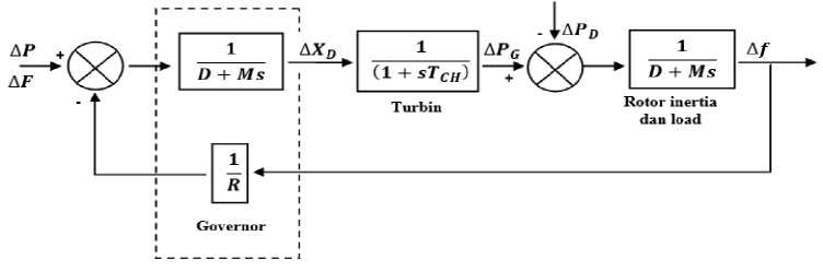
Fig. 2. Non-Reheat Turbine Block Diagram
A general Digital Electro-Hydraulic (DEH) block diagram (see Fig. 3). This diagram includes the Electro-Hydraulic Converter component, which transforms a 4-20mA signal into a change in actuator motion by varying the amount of hydraulic oil pressure[29].
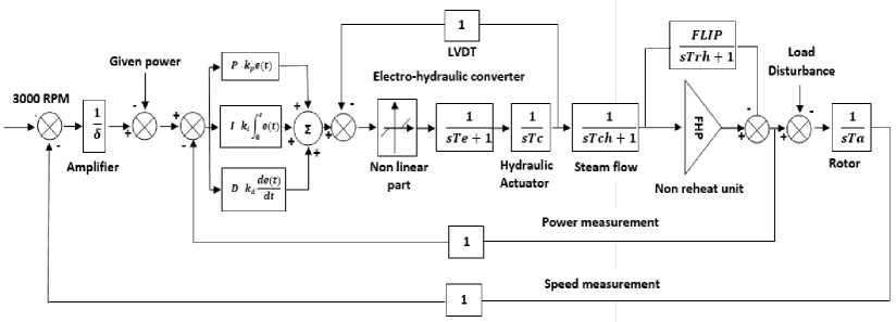
Fig. 3. DEH Control block diagram
Some parameters need to be figured out to use PID control. These parameters are Kp, Ki, and Kd, which in the previous study's parameters were also simplified (see Fig. 4) with the parameters Kp, τi, and τd. The proportional controller has a component denoted by the letter kp, the integrator controller has a part indicated by the letter τi, and the differential controller represented by the letter τd[27].
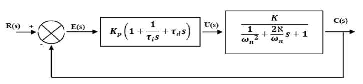
Fig. 4. Block Diagram for the Governor's PID Controller
К- .'
L . К.
ri = т
Gain = 1
Tl
Within the system are a few orders, the most important of which are the system of order 1, order 2, and orders more than 2. Each order contains a different set of parameters that make up the system. There are parameters for order 1, which can be found in (6), and there are parameters for order 2 or higher, which can be found in (7).
Parameter K , τ (4):
Parameter K, ξ, ω n (5):
Determine Kp, τi, τd (6,7,8):
к
TS + 1
4-5 2 + ^S + 1
--2 “™ шп2
2^
П = —
“ п
id = -4"
2^“ п
2К
ТС = ---- р т.шп.К
In a simulation experiment with the existing system in the PLTU Tanjung Enim plant (see Fig. 5), which is an estimation model using PID with the Ziegler Nichols tuning method[30].
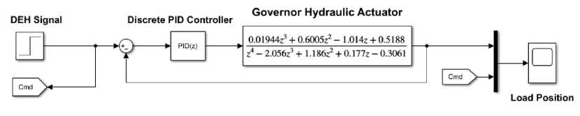
Fig. 5. Estimation of the transfer function model of a turbine system[30]
The PID control parameters for the DEH turbine's power and speed (see table.1). The table data consists of the information currently stored in the DEH input settings at the DCS PLTU Tanjung Enim 3x10MW.
Table 1. DEH Turbine Data and PID Parameters
|
Description |
Value |
|
Turbine Manufacturer |
China Changjiang Energy Corp Model: N12-4.9/475 Impulse and Condensing Turbine |
|
Pressure Initial |
4.9Mpa |
|
Temperature Initial |
475oC |
|
Rated Power |
12 MW |
|
Rated speed |
3000 rpm |
|
Rated Steam Flow |
50.8 t/h |
|
Rated Exhaust Pressure |
0.009Mpa |
|
The temperature of Cooling water |
30oC |
|
Governing System |
Digital Electro-Hydraulic (DEH) |
|
Power Mode PID |
Proportional (P) = 180 Integral (I) =50 Differential (D) =1.50 |
|
Speed Mode PID |
Proportional (P) = 35 Integral (I) =30 Differential (D) =0.50 |
-
2.7 Method of Root Locus
-
2.8 Simulink modeling in MatLab
The root locus and step response values can be seen using Matlab when using the discrete transfer function for the turbine operating model (see Fig.6).
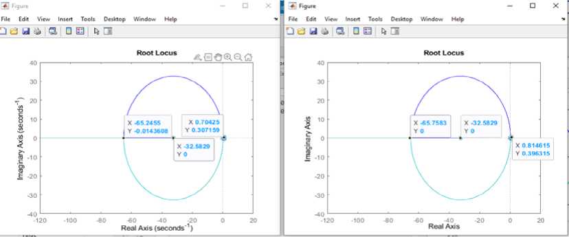
Fig. 6. The origin of the transfer function model's root locus
The findings obtained from the model's step response transfer function (see Fig.7).
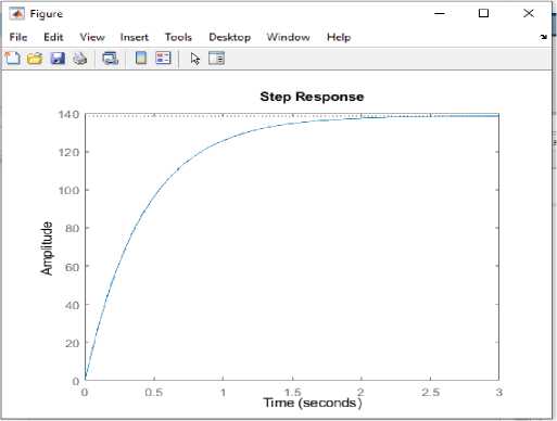
Fig. 7. Step model input response
Modeling with MatLab Simulink and running a constant signal test to see how the DEH system at PLTU Tanjung Enim 3x10MW responds. The DEH system modeling to analyze the actuator response to changes in loading and speed (see Fig. 8).
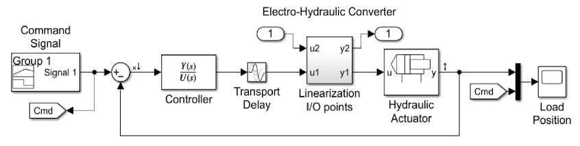
Fig. 8. Digital Hydraulic Actuator Controller with Simulink Real-Time Control
The conditions in the field at the start of the turbine are simulated model using a cold start-up procedure. Based on predetermined speed parameters, The percentage of signal and turbine governor valve opening data (see Table. 2).
Table 2. DEH signal table for Governor Turbine Valve Opening No.3
|
Percentage of DEH Signal (%) |
Level of Governor Valve Aperture (0-100%) |
Speed (Rpm) |
|
1.2 |
0 |
500 |
|
12.3 |
12 |
1000 |
|
12.3 |
12 |
1500 |
|
12.3 |
12 |
2400 |
|
11.5 |
11 |
2600 |
|
12.3 |
11 |
2800 |
|
22.1 |
22 |
3000 |
When the DEH signal is set to 0%, the actuator valve opens by 1.2 percent with a turbine speed of 500 rpm (see Fig. 9).
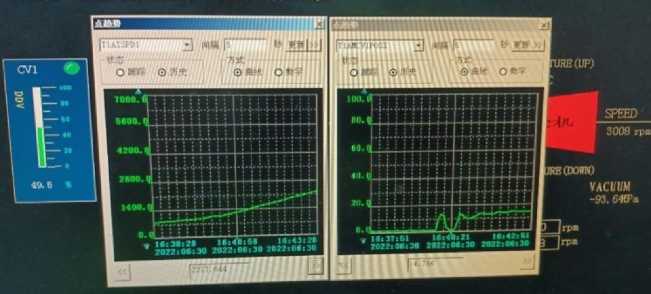
Fig. 9. Graph of DEH Signal vs. Turbine Rotation
The input signal is a digital signal with an upward sloping condition (see Fig. 10). The signal block builder shows that the signal is a digital signal from the DEH Module to close and open the Governor actuator with a good response time and a controller.
® Signal Builder (HADC/DEH Signal)
File Edit Group Signal Axes Help
2 в О • |Ъс» | - J л □ a, ^ а. в | [> j i » v ы щ у
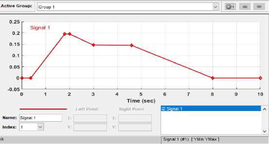
Fig. 10. DEH Signal Builder Block
3. Result and Discussion 3.1 Real-time Modeling Testing
This test is carried out by estimating the response of the Governor Actuator given to the controller to the given command using model estimates. The hydraulic response of the actuator can reach the setpoint of the DEH controller input or command signal (see Fig. 11). The following test graph depicts some of the results of the performance test modeling.
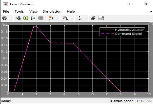
Fig. 11. Real-time model simulation
The hydraulic responsiveness of the actuator can follow the DEH signal, The graph of test results (see Fig. 11). When the DEH signal gives the order to rise at a stroke level of 0.2 m or 20 cm, the hydraulic output of the actuator follows well. The density of the DEH command signal and the actuator output signal approaches are linear (see Table. 3). The enlargement of the graph of the model test results (see Fig. 12).
Table 3. Actuator signal timing and frequency measurement data
No. Measuring point
Measurement
Time (T) Value (Y)
4.380 1.451e-01
4.390 1.451e-01
ΔT = 9.970 ms
ΔY = 7.787e-06
1/ΔT = 100.298 Hz
ΔY/ΔT = 781.016 ms Overshoot/Undershoot = --
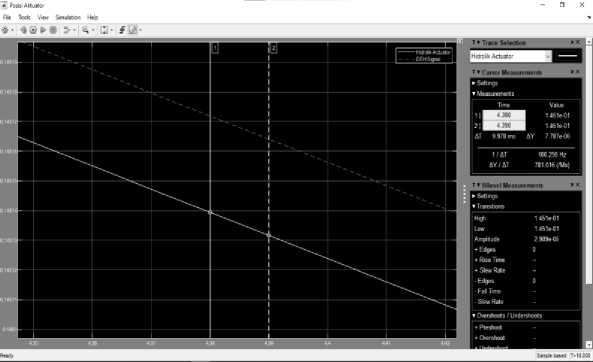
Fig. 12. Graph of the frequency magnification of the actuator signal
-
3.2 Information Evaluated and Analyzed Hydraulic Actuator
-
3.3 Evaluated and Analyzed Information Hydraulic oil supply source pressure
-
3.4 Evaluated and Analyzed Sensor Feedback Information
The response signal (command signal) about the hydraulic oil pressure and turbine actuator valve opening (see Fig. 13). The pressure through orifice A (side A) and orifice B (side B) on the electro-hydraulic converter experiences the exact change in the oil pressure graph when the solenoid's response to the given signal varies. The orifice size affects the stroke of the actuator valve to close or open, allowing steam to enter and rotate the turbine blades.
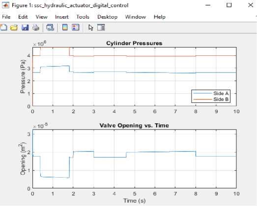
Fig. 13. Actuator Hydraulic Response Graph
The signal results for changes in the hydraulic oil source entering the actuator chamber are depicted (see Fig. 14). The graph shows that the hydraulic oil source pressure remains linear, indicating that changes in the process's input and output signals do not affect the oil pressure source, in this case as oil control or impulse oil entering the Electro-hydraulic converter.
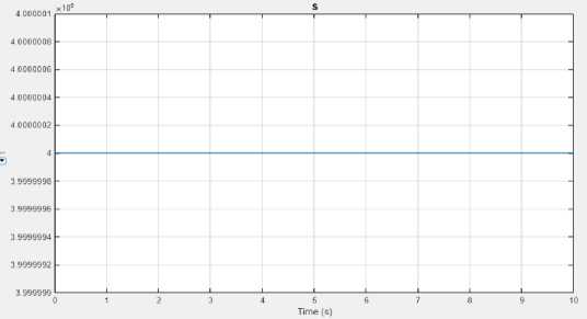
Fig. 14. Oil Pressure Distribution Graph
The form of the model, and the results of the test graph of the signal supplied to the feedback sensor that returns the command signal (see Fig. 15). This will impact the stability of the turbine's rotation in response to load changes. It takes 0.137 m/s and 0.99 seconds to achieve a stroke length of 0.08 meters.
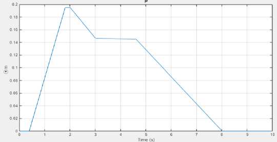
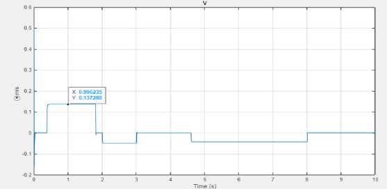
Fig. 15. Graph of signal feedback
3.5 Actuator for evaluating and analyzing data from load stem valves
4. Conclusion
The hydraulic actuator valve opening is also affected by the weight of the actuator stem valve; this will affect the actuator's response performance if the importance of the mass coupled with the actuator exceeds its tensile strength. The graphically demonstrates that the valve actuator's response can lift the 8.4 kg load from the stem valve (see Fig. 16).
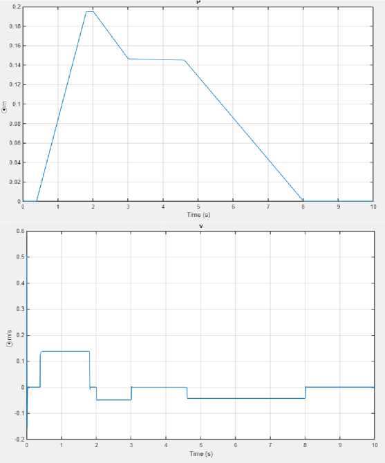
Fig. 16. Graph of signal feedback on pull load speed for the valve actuator
The design of the DEH model as a steam turbine governor control simulation model in the PLTU Tanjung Enim 3x10MW has been completed successfully. This modeling can be used to approach or fine-tune governor settings. The following conclusion can be drawn from the results of modeling experiments that have been conducted:
-
1. The transfer function model used to identify the existing steam turbine process is used to use it as the basis for tuning the control.
-
2. A PID setting with the root locus method may be employed as the controller.
-
3. This modeling can be used to determine DEH parameters such as hydraulic oil pressure and the turbine actuator stroking opening size.
-
4. With a signal density of 1/ ΔT = 100,298 Hz and ΔY/ΔT = 781,010 ms, the DEH signal response to actuator stroking can generally operate by the specified signal command.
-
5. As depicted (see Fig. 9), the controller's governor response needs completion or adjustment. At the DEH 0 percent command, the valve actuator opens, and the valve should be closed. In the sealed command condition, the turbine rotation reaches 500 rpm, or 0%, as shown in the graph.
-
6. Including all additional parameters is required to achieve the best possible result value with this modeling.
-
7. With the aid of this model, the engineering team of PT BEST, as the O&M (Operation & Maintenance) of the
-
8. For future research, it is possible to fine tune the PID Digital Electro-Hydraulic (DEH) based on the model reference made by using Matlab Software.
PLTU Tanjung Enim 3x10MW, can perform engineering before the stroke calibration.
References Digital Electro-Hydraulic (DEH) Modeling as a Steam Turbine Governor Control at PLTU Tanjung Enim 3x10MW Using MatLab
- G. Cox, L. Wiley, N. York, and A. C. Fernandez-pello, “Optimization of DEH control system based on DCS steam turbine,” 1995, [Online]. Available: http://www.zjnyxb.cn/EN/
- M. Fahreza, Hamdani, and Z. Tharo, “Pemodelan dan Pengendalian Frekuensi sistem tenaga listrik pada Simulator Pembangkit Listrik Tenaga Uap,” pp. 233–236, 2019.
- S. Sadono and N. Effendy, “Identifikasi Sistem Governor Control Valve Dalam Menjaga Kestabilan Putaran Turbin Uap PLTP Wayang Windu Unit 1,” Teknofisika, vol. 2, no. 3, pp. 83–90, 2013.
- I. Journal, O. F. Engineering, C. Of, and S. Turbine, “problem of high vibrations in servo system at over loading,” vol. 7, no. 3, pp. 309–314, 2018.
- C. Yin and J. Liu, “Study on Valve Management of DEH for Steam Turbine,” Energy Power Eng., vol. 05, no. 04, pp. 319–323, 2013, doi: 10.4236/epe.2013.54b063.
- M. Dulau and D. Bica, “Simulation of Speed Steam Turbine Control System,” Procedia Technol., vol. 12, pp. 716–722, 2014, doi: 10.1016/j.protcy.2013.12.554.
- D. D. Istiawan, R. Syahputra, and K. T. Putra, “Analysis of Steam Power Generators in Fulfilling Electricity Needs : A Case Study at PT Madubaru Yogyakarta , Indonesia,” vol. 1, no. 4, pp. 189–195, 2017.
- S. T. Saputro, “Pengendalian Laju Aliran Massa Uap Masuk Intermediate Pressure Turbine ( Ipt ) Pada Pembangkit Listrik Tenaga Uap Berbasis Distributed Control System ( Dcs ),” no. I, pp. 149–160, 2015.
- S. Reddy, I. Ahmed, T. S. Kumar, a V. K. Reddy, and V. V. P. Bharathi, “Analysis Of Steam Turbines 1,” Int. Ref. J. Eng. Sci., vol. 3, no. 2, pp. 32–48, 2014.
- I. Engineering, “Speed Controller Design for Steam Turbine,” Int. J. Adv. Res. Electr. Electron. Instrum. Energy, vol. 2, pp. 4400–4409, 2013.
- F. L. Everett, B Woodruff; Herbert, B Lammers; Thomas, Steam Plant Operation, 8th Editio.
- M. Pondini, A. Signorini, and V. Colla, “Steam Turbine control valve and actuation system modeling for dynamics analysis,” Energy Procedia, vol. 105, pp. 1651–1656, 2017, doi: 10.1016/j.egypro.2017.03.539.
- R. B. Walters, Hydraulic and Electric-Hydraulic Control Systems. 2000. doi: 10.1007/978-94-015-9427-1.
- A. Feyo, A. R. Thelkar, C. Bharatiraja, and Y. Adedayo, “Reference design and comparative analysis of model reference adaptive control for steam turbine speed control,” FME Trans., vol. 48, no. 2, pp. 329–341, 2020, doi: 10.5937/FME2002329F.
- M. T. Nguyen, T. D. Dang, and K. K. Ahn, “Application of electro-hydraulic actuator system to control continuously variable transmission in wind energy converter,” Energies, vol. 12, no. 13, 2019, doi: 10.3390/en12132499.
- G. V. Patil and N. R. Kulkarni, “Simulation of Electro-Hydraulic Turbine Control ( EHTC ) System,” Ijaeee, vol. 2, no. 2, pp. 292–299, 2013.
- M. A. Lilo, “Using Vibration Signal with EHC System to,” no. 6, pp. 1805–1815, 2014.
- S. Salleh, M. F. Rahmat, S. M. Othman, and K. A. Danapalasingam, “Review on modeling and controller design of hydraulic actuator systems,” Int. J. Smart Sens. Intell. Syst., vol. 8, no. 1, pp. 338–367, 2015, doi: 10.21307/ijssis-2017-762.
- J. Wang, A. Song, and Y. Kang, “Analysis and treatment of jitter for 300MW steam turbine high-pressure control valve,” E3S Web Conf., vol. 271, pp. 7–10, 2021, doi: 10.1051/e3sconf/202127101018.
- Z. H. Wang, “Condition analysis of steam turbine digital electro-hydraulic control system based on data fusion,” Appl. Mech. Mater., vol. 602–605, no. Iceep, pp. 954–957, 2014, doi: 10.4028/www.scientific.net/AMM.602-605.954.
- C. Ma, C. Liu, and X. Zhang, “Fixed-time feedback control of the hydraulic turbine governing system,” Complexity, vol. 2018, 2018, doi: 10.1155/2018/8767158.
- J. Laghari, H. Mokhlis, A. B. H. A. Bakar, and H. Mohammad, “Comparative studies on load frequency control for islanded distribution network connected with mini hydro,” 2011 5th Int. Power Eng. Optim. Conf. PEOCO 2011 - Progr. Abstr., pp. 211–216, 2011, doi: 10.1109/PEOCO.2011.5970388.
- B. T. Nanaware, R a , S.R, Sawant , Jadhav, “Modeling of Hydraulic Turbine and Governor for Dynamic Studies of HPP,” Int. Conf. Recent Trends Inf. Technol. Comput. Sci., pp. 6–11, 2012.
- S. H. Yanghai Li, “The impact research of control modes in steam turbine control system (digital electric hydraulic) to the low-frequency oscillation of grid _ Enhanced Reader.pdf.” SAGE, 2016. doi: 10.1177/1687814015624835.
- W. Ali, H. Farooq, W. Abbas, M. Usama, and A. Bashir, “Journal of Faculty of Engineering & Technology PID VS PI CONTROL OF SPEED GOVERNOR FOR SYNCHRONOUS GENERATOR BASED GRID CONNECTED,” vol. 24, no. 1, pp. 53–62, 2017.
- J. Zhao, L. Wang, D. Liu, and J. Wang, “Piecewise Model and Parameter Obtainment of Governor Actuator in Turbine,” J. Appl. Math., vol. 2015, pp. 15–19, 2015, doi: 10.1155/2015/709272.
- A. A. Firdaus, “Desain Model Kontrol Governor Dengan Menggunakan Kontroler PID Di PLTU,” Jurnal Intake, vol. 7, no. 2. pp. 33–40, 2016.
- R. Arindya, “Penalaan Kendali PID untuk pengendali proses,” J. Teknol. Elektro, vol. 8, no. 2, p. 109, 2017.
- D. Zhu and L. Luo, “Design of DEH Test Platform for Steam Turbine ’ s Hydraulic Actuator Valve Use,” vol. 1, no. Icmmbe, pp. 386–391, 2016.
- S. M. Rozali, M. F. Rahmat, N. Abdul Wahab, R. Ghazali, and Zulfatman, “PID controller design for an industrial hydraulic actuator with servo system,” Proceeding, 2010 IEEE Student Conf. Res. Dev. - Eng. Innov. Beyond, SCOReD 2010, no. June 2014, pp. 218–223, 2010, doi: 10.1109/SCORED.2010.5704005.
