Динамика агрегата машины с фрезерным механизмом разборщика бунтов хлопка

Автор: М.Т. Ходжиев, А. Джураев, А.К. Ашуров
Журнал: Современные инновации, системы и технологии.
Рубрика: Прикладные вопросы и задачи применения систем и технологий
Статья в выпуске: 2 (3), 2022 года.
Бесплатный доступ
В статье рассматривается вопрос динамики агрегата машины, которая включает в себя разборщик бунтов хлопка, с учетом механической характеристики электрического двигателя, технологического сопротивления и момента сил трения. Определен закон движения фрезы. Показана зависимость коэффициента вращательного момента резиновой втулки, установленной на фрезерных головках, от вибрационного значения угловых скоростей вращающегося приводного барабана, угловой скорости приводного ротора и крутящего момента. По результатам анализа графиков связи были рекомендованы оптимальные значения параметров
Разборщик бунтов хлопка, фреза, колосник, машинный агрегат, упругая втулка, технологическое сопротивление, прочность, момент инерции, угловая скорость, покрытие, производительность, эффективность очистки
Короткий адрес: https://sciup.org/14123671
IDR: 14123671 | УДК: 677.021 | DOI: 10.47813/2782-2818-2022-2-3-0201-0210
Текст статьи Динамика агрегата машины с фрезерным механизмом разборщика бунтов хлопка
DOI:
As we know, the main working body of the cotton bundle disassembler machine is a peg or milling drum, which has a number of design solutions [1, 2]. Nevertheless, the separation of the cotton pieces from the bundle was mainly done from the top down. In this case, the cotton pieces are not well hung with pegs, the incidence of spillage is high. Therefore, a method of separating the cotton pieces from the bottom up was recommended. In this case, the cotton pieces are separated in one plane without spilling and passed through a tube in the air stream [3].
The advantage of the recommended milling drum is that it is made of composite, mounted on the milling cutter shaft by means of flexible rubber bushings. In this case, the rotational motion of the milling drum is due to the deformation of the rubber bushing [4]. Because of these rotational movements, the milling drum intensively separates the cotton pieces from the peg, shaking it. This means that along with the increase in productivity, the efficiency of partial cleaning will also increase.
CALCULATION SCHEME AND MATHEMATICAL MODEL OF THE MACHINE AGGREGATE
The milling drum receives motion through an electric drive, a transmission shaft, a conical gear reducer. The calculation scheme is shown in Fig. 1. In the scheme, the milling drum was considered as one whole without being divided into two. However, the rubber bushing was taken into account.
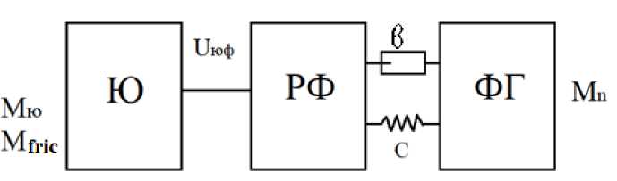
/оф , ф2 Уф2 , фз
J кю ,
Figure 1. Calculation scheme of the machine aggregate.
In order to obtain the mathematical model of a cotton bundle disassembler machine aggregate, we calculate using Lagrange's second-order equation [5,6].
d (дт\ дт дф дп_ jfU)—^+^+^ —Q(qt) (1)
where Т, П are the kinetic and potential energies of the system, Ф is the dissipative function of the relay, Q(qt) are the external forces; qt is generalized coordinate.
System kinetic and potential energies are [6,7]:
1 • 1 • 1
T — -/ кю Ф 2 + ^Рф Ф г + 2^ф2 Ф з
П - "С(Ф 2 - ^ 2з Ф з )
where ф 1 , ф2, фз are the angular apeeds of the electric drive shaft, the gearbox output shaft and the drum shaft and the milling headset, respectively, С is the coefficient of rotation of the rubber bushing; U23 is transmission ratio.
The dissipative function of the relay is [8]:
Ф- 1 ь(Ф 2 -и 2з Ф з )2 (3)
where 6 is the dissipation coefficient of rotation of the rubber bushing.
Correspondingly, we create a mathematical model representing the motion of a three-mass machine aggregate by determining the additions of the Lagrange equation for each generalized coordinate [8,9]:
^ 0-0 1 sk , 1
Ш 0 — 2Mk М + 2шсМн Mg
1 кю Ф 1 — Мю — июфМюф — Mfrtc
/рфф2 — Мюф — С(ф 2 — и2зФз ) — Ь (Ф2 — и2зФз )
Уфг Ф з — и 2з * С(Ф 2 — и 2з ф 2 ) + и 2з Ь(ф 2 — и 2з ф з ) — (М 1 + M o S k Wt+8M;) (4)
where M 1 , M0 , 6M 1 are constant and variable random components of technological resistance; Мю ф is driving torque interacting between the drive and reducer output shaft, M f ric is the moment of resistance of frictional forces.
NUMERICAL SOLUTION OF THE PROBLEM AND ANALYSIS OF RESULTS
The solution of the system of differential equations (4) representing the motion of the machine aggregate, including the milling drum drive of the cotton bundle disassembler, was carried out using the Runge-Kutta program [5,10], considering the following initial calculated values of parameters
/кю = 1,52 kgm2 /юф = 5,25 kgm2
/ф г = 1,69 kgm2 июр = 6,83 kgm2
Ф 1 = 157 s-1 пю = 1500 rpm-1
М^с = 8,17 N М 1 = (20 — 25) N
М0 = (2,1 — 2,5) N 5М 1 = (0,1 — 0,12) М 1
С = (450 — 500) Nm/rad 6 = (6,2 — 7,5) Nms/rad
Based on the solution of the problem, the laws of motion of the working bodies of the machine unit were determined. Fig. 2 shows the laws of variation of the angular speed of the rotor of the electric drive rotor and the torque in it, as well as the torque on the output shaft of the reducer.
The analysis of the obtained laws shows that the average start-up time of the machine unit is (0.2÷0.25) s, while the stopping period is (0.18÷0.2) s. The difference in this is mainly explained by the fact that the moments of resistance forces accelerate the stopping. Considering that the technological resistance was in the process of breaking the cotton gin, it was found that the average value of ф)1was around 153 s-1, the loading value was around М ю = (31^35) Nm, and the loading of М фг was around (68÷75) Nm.
Figure 3 shows the laws of variation of angular speeds ф 1 ф3 and torques on the shafts Мю М фг of the drive and milling headset.
Because result of processing the obtained laws of motion and loads, graphs of the interrelationships of machine unit parameters were constructed. In particular, Figure 4 shows 0204
graphs related to the technological resistance of the milling drum, the oscillation coverage of the angular speeds of the drive rotor and the changes in the torque. When analyzing the graphs, the angular speed oscillation coverage of the electric drive shaft when the moment of resistance from the raw cotton obtained increases from 0.42ˑ10 N to 3.8ˑ10 N is 2.18ˑ10 s-1 to 5.2ˑ10 s-1 increases the angular speed coverage of the milling headset from 1.51ˑ10 s-1 to 3.6ˑ10 s-1. Correspondingly, as the torque values on the electric drive increase from 0.04 ˑ 102 Nm to 0.12ˑ102 Nm, the load on the milling headset increases from 0.09ˑ102 Nm to 0.32ˑ102 Nm in a nonlinear connection (Fig. 4, 4-graph). It is known that the speed of the milling cutter is much higher than the rotational motion, which allows intensive separation of cotton from the mill.
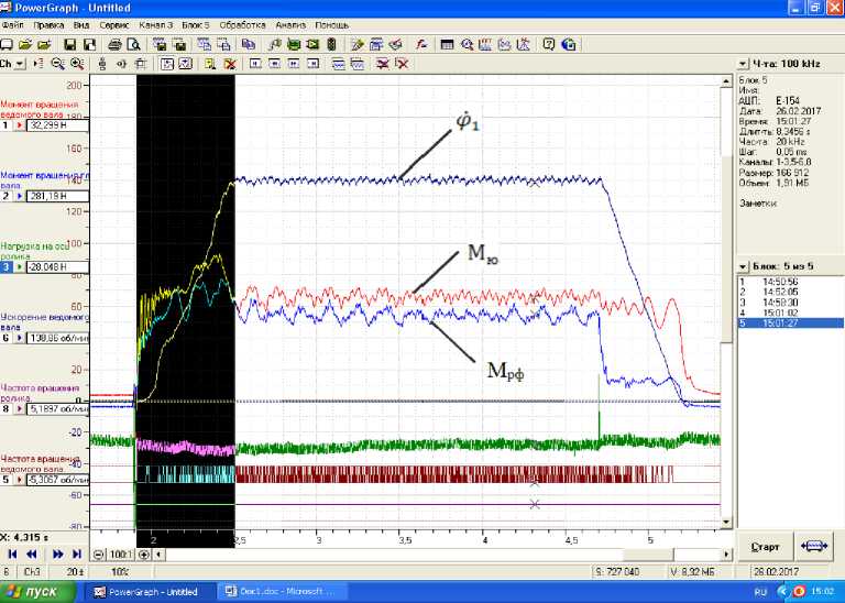
Figure 2. Laws describing the output to stable motion, stable motion period and stopping processes of the machine aggregate, including the mechanism of the milling drum of the cotton bundle disassembler.
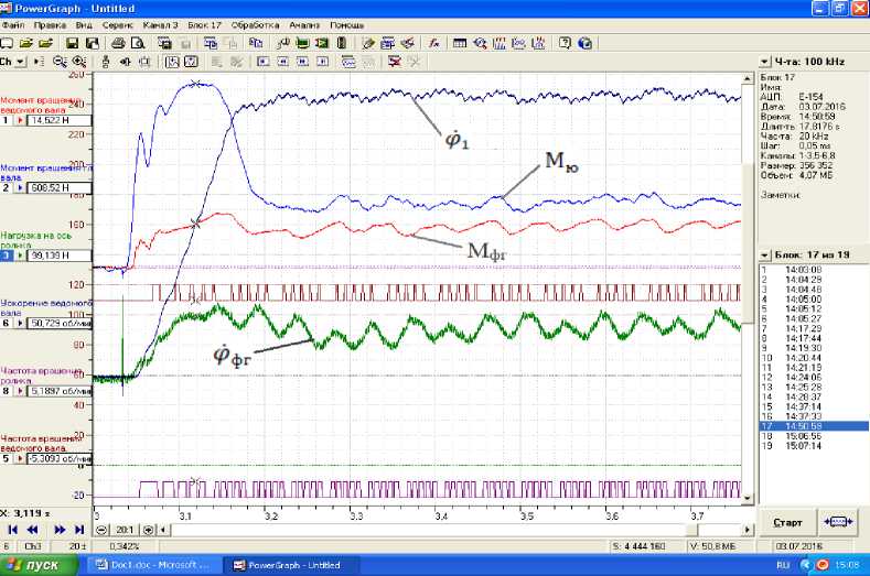
Figure 3. The laws of change of angular speeds and torques of the drive and milling headset.
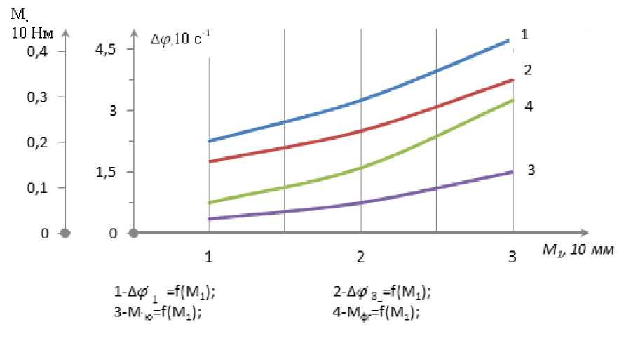
Figure 4. Graphs of technological resistance dependence of changes in the vibration coverage of angular speeds and torque moments of the spinning mill drum and the drive rotor.
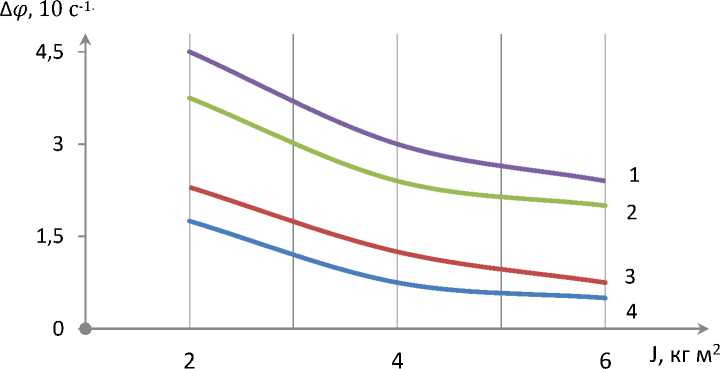
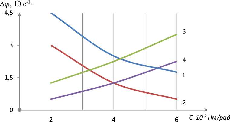
Fig. 5 shows the dependence of the rotational torque coefficient of the rubber bushing mounted on the milling heads on the vibrating coverage of the angular velocities of the rotary drive drum, the angular speed of the drive rotor, and the torque. When the average torque coefficient of the rubber bushing on the milling drum increases from 1.0ˑ102 Nm/rad to 6.00ˑ102 Nm/rad, the oscillation coverage of the angular speed of the milling headset is 2.61ˑ10 s-1 to
0.64'10 s-1. If it decreases in a nonlinear pattern up to 1, it can be seen that the values of &ф 1 decrease in a nonlinear pattern from 4.4ˑ10 s-1 to 1.58ˑ10 s-1 (Fig. 5, graph 1). It should be noted that if the torque on the drive shaft increases from 0.052ˑ102 Nm to 0.18ˑ102 Nm, the torque on the milling headset increases from 0.12ˑ102 Nm to 0.33ˑ102 Nm in a non-linear connection.
It is recommended that the rubber bushing average rotational coefficient of rotation be less than (4.0÷5.0) Nm/rad to ensure that the speed vibration coverage (0.6÷1.6) is in the range of 10 s-1.
1-Д
р
=f(C) 2-A 3=f(C) 3-Mro=f(C) 4-Мфr=f(C) Figure 5. Graphs of the dependence of the coefficient of rotation of the rubber bushing on which the milling heads are mounted on the rotating torque, the vibration coverage of the angular speeds of the drive rotor and the torque moments of the milling cutter. It should be noted that by increasing the weight of the rotating mass or the moment of inertia, it is possible to make its rotation smooth [10-12]. Fig. 6 shows graphs of the vibration coverage of the angular speeds of the spinning mill drum and the drive rotor depending on the change in their moment of inertia. When the moment of inertia of the cutter headset increases from 1.2ˑ10 m2 to 5.0ˑ10 m2, when the coverage of the rotational oscillation speed of its angular speed is Мишк= 5.0 Nm, the values of ^ф3 decreases from 1.52'10 s-1 to 0.26'10 s-1, while Мишқ=9.0 Nm, the angular speed coverage of the milling headset decreases in a nonlinear pattern from 2.25'10 s-1 to 0.61'10 s-1. Correspondingly, the values of &ф1 on the electric drive shaft decrease in a nonlinear pattern from 4.6ˑ10 s-1 to 2.28ˑ10 s-1 (Fig. 6, graph 1, 2). However, an excessive moment of inertia increases the loading torque and increases the power consumption. Therefore, the recommended values are: /ю < (2.0 ^ 2.5)kgm2; /фг < (2.4 ^ 3.5) kgm2. 1,2- Д(p.1=f(Jкю) 3,4-Дy.1=f(Jфr) 1,3- Мfric=5.0 Nm; в=4.5 Nms/rad 2,4- Мfric=9.0 Nm; в=7.0 Nms/rad Figure 6. Graphs of the dependence of the vibration coverage of the angular speeds of the spinning mill drum and the drive rotor on the change in their moments of inertia. THE RESULTS OF THE PROPOSED TEST OF THE CONSTRUCTION OF THE DRUM WITH A MILLING CUTTER, FLEXIBLE SHOCK ABSORBER OF THE RECOMMENDED COTTON BUNDLE DISASSEMBLER Analysis of the comparative test results shows that when using the recommended cotton bundle disassembler milling drum, the productivity can be increased by 1.9 t/h compared to the existing working body. Cotton cleaning has also improved. At the same time, it was found that for every 10 kg of raw cotton (up to 4÷5) the number of pieces with up to 24% more fiber than the existing design, i.e. improved cotton cleaning. As a result, it was found that the cleaning efficiency of cotton increased by 5.9%. It was also noted that due to the use of a rubber shock absorber in the proposed design, the damage to the seeds because of the soft impact was reduced by 0.08÷0.09% after the UXK unit. The efficiency of cleaning cotton after the cleaning unit was found to be 88.0% when using the recommended construction, and 79.5% when using the series construction. This means that the use of the recommended working drum in the cotton bundle disassembler machine leads to high efficiency. Table 1. Comparative test results. No. Name of the parameters In existing cotton bundle disassembler In proposed cotton bundle disassembler 1. Initial contamination of cotton, % 3.4 3.4 2. Cotton moisture, % 8.5 8.5 3. Productivity, t / h 10.5 12.4 4. Efficiency of cotton cleaning, % 7.9 13.8 5. Efficiency of cotton cleaning after UXK aggregate, % 79.5 88.0 6. Seed damage, % 1.4 1.32 7. Degree of shredding of cotton (percentage of pieces of up to 5 fibrous seeds in 10 kg of raw cotton), % 85 61 CONCLUSIONS The efficient design of a milling drum of the cotton bundle disassembler is recommended. Based on the theoretical research, the laws of motion and loads of the drive and milling headset were determined, and the optimal parameters were recommended. Based on the test results, recommendations for implementation are given.