DTC-SVM based on interval type-2 fuzzy logic controller of double stator induction machine fed by six-phase inverter

Author: Hellali Lallouani, Belhamdi Saad, Benyettou Letfi
Journal: International Journal of Image, Graphics and Signal Processing @ijigsp
Article in issue: 7 vol.11, 2019.
Free access
The main disadvantage of the classical direct torque control is high torque and flux ripples. This is due to hysteresis comparators suffer from a variable switching frequency and a high torque ripple. Besides, a hybrid strategy; Direct Torque Control with Space Vector Modulation (DTC -SVM) is established using Interval Type-2 Fuzzy Logic Controller (IT2FLC) for enhancing control performance parameters to reducing torque and flux ripple. In this work, a IT2FLC is applied to the DTC-SVM of Double Stator Induction Machine (DSIM). Simulation results are shown to present the robustness and efficiency of the recommended control strategy.
Double stator induction machine (DSIM), Six-phase inverter, Interval Type-2 fuzzy logic controller (IT2FLC), Direct torque control with space vector modulation (DTC-SVM)
Short address: https://sciup.org/15016067
IDR: 15016067 | DOI: 10.5815/ijigsp.2019.07.04
Text of the scientific article DTC-SVM based on interval type-2 fuzzy logic controller of double stator induction machine fed by six-phase inverter
Published Online July 2019 in MECS DOI: 10.5815/ijigsp.2019.07.04
Over the last decade, Alternating Current (AC) motor the most used in industrial applications, these motors divided by the number of stator phases ( q) into several types: two-phase machines (q = 2), three-phase machines (q = 3) and multi-phase machines ( q > 3). Usually, multiphase machines replace three-phase machines in several applications such as; locomotive traction, electric vehicles, rolling mills, mine hoists and cement mills [1,3], because of this machine has high reliability, minimizing the rotor harmonic currents and minimized torque pulsations [2].
The control of the DSIM draws attention to several researchers like scalar control, field oriented control, direct torque control, sliding mode control and back stepping control. The DTC established by I. Takahashi in1980 [4], This latter is used the errors between the estimated and the reference values of flux and torque for minimization the flux and torque errors within the band limits. This scheme is allow us to directly control the inverter states [5]. However, conventional DTC has several drawbacks: difficult to control torque and flux into low speed, large torque ripple, variable switching frequency, torque and current distortion at the change of the sector and high sampling frequency needed for digital implementation of hysteresis bands [5,6].
For the solution of these disadvantages in using multilevel inverter, Space Vector modulation (SVM). In addition, the combination between DTC and SVM produced it a technique called DTC-SVM [11]. This method uses the SVM instead of a switching table to give inverter-switching state and replace the hysteresis band with conventional Proportional Integral (PI) controllers. The PI controllers are simple but cannot robustness control 1 systems with varying parameters or have a nonlinearity [9,10]. Furthermore, fuzzy logic is a scheme used in artificial intelligence and widely utilized in different areas including the control and the automation [15]. The application of interval type-2 fuzzy logic has been a success and it is able to control machines with measurement uncertainties [17]. Does not need a detailed model [18], interval type-2 fuzzy logic controllers are one of useful control schemes to adjust the speed, torque and stator flux of DSIM. In this work, the DTC-SVM-IT2FLC is developed for DSIM in order to evaluate the performance of the system to obtain the integral time-weighted absolute error (ITAE), integral absolute error (IAE) and integral squared error (ISE) for the proposed scheme (DTC-SVM-IT2FLC) and to compare it with other schemes as DTC-SVM-T1FLC and DTC-SVM-PI.
This paper is organized as follows: in section 2, the model of the DSIM and six-phase inverters is presented. Next, we will describe the DTC-SVM by a IT2FLC in section 3. Section 4 shows simulation results for the performance of IT2FLC controller of DTC-SVM-DSIM under various conditions operation. Finally, a general conclusion summaries this work.
-
II. Machine and Inverter Models
-
A. DSIM Model
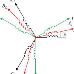
The DSIM is composed by three winding as follows[3]:
-
• Two stator windings, which are shifted by an electric angle of 30°.
-
• The rotor winding is shifted sinusoidal repartition by an angle of (120°) relative to the stator windings.
To simplify the model of the DSIM has used set of assumptions have following:
The windings are sinusoidal distributed, the flux path is linear, The two stator windings have the same parameters, core losses and the magnetic saturation are neglected [13].
The windings of the DSIM are shown in Fig. 1;
B r
ROTOR
STATOR 2
As 2
STATOR 1 A
Cr s1
C s 2
Fig.1. DSIM winding representation.
The model of DSIM is set a nonlinear differential equations, using the vector space decomposition, its T matrices of transformation [7]:
|
1 |
1 — 2 |
1 — 2 |
3 2 |
3 — 2 |
3 — 2 |
|
|
0 |
3 |
3 |
1 |
1 |
1 |
|
|
2 |
2 |
2 |
2 |
2 |
||
|
T s ( a ) ] = |
1 |
1 — |
1 — |
3 — |
3 |
0 |
|
2 |
2 |
2 |
2 |
|||
|
1 |
1 |
|||||
|
0 |
0 |
0 |
-1 |
|||
|
2 |
2 |
|||||
|
1 |
1 |
1 |
0 |
0 |
0 |
|
|
.0 |
0 |
0 |
1 |
1 |
1 |
The voltage, Current and flux space vectors of the DSIM can be mapped into two-dimensional orthogonal subspaces: α1-β1, α2-β2 [7].
• Electrical equations
|
Г к 1 v sa 1 |
■ Rs 1 |
0 |
0 |
0 |
0 |
0 " |
I s a 1 |
||
|
V. |
0 |
R s 1 |
0 |
0 |
0 |
0 |
I s p 1 |
||
|
V s a 2 |
0 |
0 |
R s 2 |
0 |
0 |
0 |
1 s a 2 |
||
|
у r se 2 |
0 |
0 |
0 |
Rs 2 |
0 |
0 |
I s P 2 |
||
|
0 |
0 |
0 |
0 |
0 |
R r |
0 |
I ™ |
(1) |
|
|
. 0 J |
. 0 |
0 |
0 |
0 |
0 |
R r J |
. I r e _ |
||
|
+ |
|||||||||
|
L s 1 |
0 |
0 |
0 |
0 |
0 " |
"Ф s a 1 " |
|||
|
0 |
Ls 1 |
0 |
0 |
0 |
0 |
Ф в |
|||
|
0 |
0 |
Ls 2 |
0 |
0 |
0 |
d |
Ф s a 2 |
||
|
0 |
0 |
0 |
Ls 2 |
0 |
0 |
dt |
Ф s e 2 |
||
|
0 |
0 |
0 |
0 |
L r |
0 |
ф r a |
|||
|
. 0 |
0 |
0 |
0 |
0 |
L r J |
Ф r e _ |
|||
• Flux equation;
|
Ф sa 1 |
" L s 1 + L m |
0 |
L m |
0 |
L m |
0 ’ |
" Isa 1 |
||
|
Ф в |
0 |
L s 1 + L m |
0 |
L m |
0 |
Lm |
I se 1 |
(2) |
|
|
Ф sa 2 |
L m |
0 |
L s 2 + L m |
0 |
L m |
0 |
I sa 2 |
||
|
Ф sP 2 |
^ |
0 |
L m |
0 |
L s 2 + L m |
0 |
Lm |
I s» 2 |
|
|
Ф ra |
L m |
0 |
L m |
0 |
L r + L m |
0 |
I ra |
||
|
. Ф re |
. 0 |
L m |
0 |
L m |
0 |
L r + L m J |
[ I e |
• Equation of electromagnetic torque;
• Mechanical Equation;
dt
-
B. Six-Phase Inverter Model
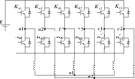
The stator windings of DSIM are fed by a six-phase inverter as illustrate in Fig. 2[6,7].
K '
K
K '
K
o
Fig.2. Schematic diagram of a six-phase inverter.
b 1
K '
b 2
K '
K a1 ,K b1 ,K c1 : The switches of the upper half bridge.
K a2 ,K b2 ,K c2 : The half bridge inferior.
o: The neutral point of the source.
n 1 ,n 2 : The neutrons of stator 1 and stator 2.
sequence components since the neutral are not relies. Therefore:
V a1 + V + V c1 = 0
V sa 2 + V sb 2 + V sc 2 = 0
t в 1
20 62
14 13
L1
57 48
L3
54 L4 32
1 43
The voltage vector of the six-phase inverter is
expressed as follows[6]:
L2
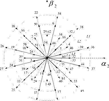
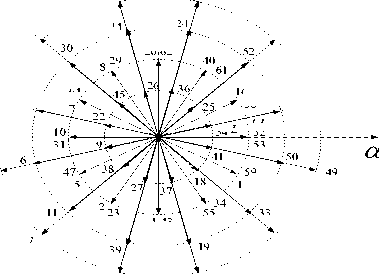
Fig.3. Inverter voltage vectors in α1 - β1; α2 - β2 subspace.
Fig.3 illustrate a total of The 64 voltage vectors can be projected into the subspaces of (α 1 ,β 1 ) and (α 2 ,β 2 ) from combining all the states of the switches 12[6], where we note that each case is represented by a decimal number based on binary value of S a1 ; S b1 ; S c1 ; S a2 ; S b2 ; S c2 [7].
S a;b;c (1 ; 2 ; 3) = (0 ; 1).
L1, L2, L3 and L4 : The amplitudes of four groups for the voltage vectors.
The phase voltage can be expressed as follows[6]:
|
Vsa 1 |
Va 1 n 1 |
Va 1 o |
+ Von1 |
|
|
V |
Vb 1 n 1 |
Vb 1 o |
+ Von1 |
|
|
V |
Vc 1 n 1 |
Vc 1 o |
+ Von1 |
(5) |
|
Vsa 2 |
= y, , a 2 n 2 |
= V a 2 o |
+ V on 2 |
|
V sb 2 |
= V r b 2 n 2 |
= V b 2 o |
+ Von 2 |
|
у I V sc 2 |
= v. ? c 2 n 2 |
= V c 2 o |
+ Von 2 |
Assuming that the windings of the stator 1 and stator 2 are balanced, the phase voltage cannot contain zero
|
V sa 1 " |
" 2 |
—1 |
—1 |
0 |
0 |
0 " |
"Va 1 o " |
||
|
Vsb 1 |
— 1 |
2 |
—1 |
0 |
0 |
0 |
Vb 1 o |
||
|
Vsc 1 |
— 1 |
—1 |
2 |
0 |
0 |
0 |
V c 1 o |
(6) |
|
|
Vsa 2 |
■ |
° |
0 |
0 |
2 |
—1 |
— 1 |
V a 2 o |
|
|
Vsb 2 |
0 |
0 |
0 |
—1 |
2 |
— 1 |
V b 2 o |
||
|
V sc 2 _ |
_ ° |
0 |
0 |
—1 |
—1 |
2 _ |
V c 2 o _ |
[ V s ] = C K d ] [\ ] = E [ S ] = E [ S a 1 S a 2 S b1 S b 2 SC 1 SC 2 ]
III. DTC-SVM-DSIM Strategy Control
Fig. 4 show the proposed DTC-SVM with IT2FLC scheme of DSIM fed by six-phase inverter. This method suggest the use of three controllers of interval type-2 fuzzy logic for speed, torque and stator flux to replace the classical PI. The exit of controllers of the torque and flux generate the references stators voltages components ( U X 1 ;U Y 1 ) ( U X 2 ; U Y 2 ). This components are continuous voltage commands and then transformed into stationary coordinates ( α - β ) the controlled values ( Uα 1 ; U β 1 ) and
( Uα 2 =0 ;U β 2 =0) are delivered to SVM which give rise to switching signals Sa 1 ; Sb 1 ; Sc 1 ; Sa 2 ; Sb 2 ; Sc 2 for the six phase inverter [6,7,8].
A. Flux and Torque estimations
In this part, estimating the amplitude and angle position of stator flux and torque. So[11]:
Фsk(a,P) = J (Vsk(a,в) — RsIsk(a^) )
ˆ ˆ 2 ˆ 2(8)
sk \ ska ske
^sk = arctg
Ф ,
C em = P
' ((Ф s оЛ 1 в
\ sk a у
— Ф s 1 e I s 1 a ) + ( ф s2 a 1 s 2 в
—
ˆ
Ф s 2 в I s 2 a
) (1°)
and k=(1;2)
B. Space vector with Modulation
In this part, estimating the amplitude and angle position The objective of the SVM technique is to give the switching signals of the six phase inverter. The preciseness of the control scheme depends on the precision estimation of the amplitude of the torque and
the amplitude and position of the stator flux. A proposed SVM scheme of the DSIM is based on two steps, The first is to use two original switching vectors to synthesize the new vectors by forcing the second volts means of the voltage vectors in the subspace α2-β2 to zero (Uα2 = 0, Uβ2 = 0). The second is to use two synthesized vectors without harmonics to compose the Vref reference voltage vector based on SVM classical [6,8].
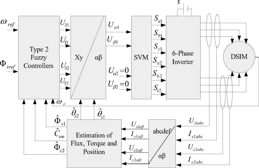
Fig.4. Proposed of DTC-SVM with Interval type-2 fuzzy logic control strategy
For example, the new vector V 3 is synthesized by vector 24 and vector 60, and has the amplitude of 0.598 E in α 1 -β 1 subspace and zero in α 2 -β 2 subspace (Fig. 5).
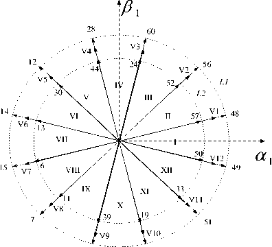
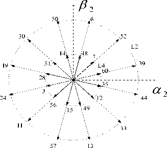
Fig.5. Selected and synthesized vectors in α1 - β1; α2 - β2 subspace.
In each sector, every voltage vector is composed from basic space voltage vector of the four side of sector (V a , V b , V c , and V d ) and one zero vector:
Va, V b , V c , and V d : The original voltage vectors.
V ac ,V bd : are newly composed vectors in the first step.
For example, The vectors 28, 44, 24 and 60 are used to compose the reference voltage vector V ref from a two-step synthesis process in sector IV. As shown in Fig. 6.
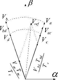
Fig.6. Projection of the reference voltage vector in sector IV.
The calculated times T 1 , T 2 , T 3 and T 4 are applied to the switches to produce space vector of six phase inverter switching patterns based on every sector.
For this, using four equations with four unknown times as follows (V sα1ref ; V sβ1ref ),(V sα1ref = 0; V sβ1ref = 0) [8]:
fTV +TV +TV +TV -TV
-
11 vs « 1 + A2 vs a 2 + A3 vs a 3 + 14 v s a 4 Ae vs a 1ref
TV + TV +TV +TV = T V
-
T 1 V s в 1 + T 2 V s в 2 + T 3 V s в 3 + T 4 V s в 4 T e V s ^ 1ref
-
(11)
-
11 V s a 1 + V V s a 2 + V V s a 3 + V V s a 4 V V s a 2ref u
TV +TV +TV +TV -TV -0
T I V s e i + T 2 V s в 2 + T 3 V s в 3 + T 4 V s e 4 T e V s в 2ref 0
V sα1 V sβ1 : Reference value of tension ; Times T i denote the required on-time of the active-state vectors V i during each sample period T e ; T n denote time of the null state vectors
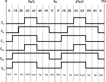
Fig.7. Leg voltages and space vector disposition in sector IV.
Fig. 7 shown The leg voltage in one switching period for sector VΙ. the signals should be distributed symmetrically to the middle of the PWM period to reduce the switching number [6].
-
C. Design of Interval Type 2 Fuzzy Logic Controller
In this section, the interval type-2 fuzzy logic controller replaced the PI controller for to reduce the time response while preserving the system stability and cancel the static error. Generally, the IT2FLC can handle complicated non-linear systems which have a degree of uncertainty [17]. It does not need a precise model of the system and the exact values of the parameters[18].
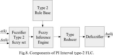
The interval type-2 fuzzy logic contain four elements are[17,19]:
-
• Fuzzification: convert classical data into
Membership Functions (MFs) such as NB (Negative Big), B (Big).....
-
• Fuzzy Inference Engine: this element depends on the lookup table, which summarizes our control derivatives resulting, from the link that combines the control rules and MFs.
-
• Type Reducer: this component of interval type-2 fuzzy logic, to reduce the type-1 fuzzy set output and transfer to the defuzzification.
-
• Defuzzification: type reducer you take a type-1 fuzzy set output, and the defuzzification to convert MFs into crisp data.
The DTC-SVM use the IT2FLC give an excellent system performance. In this part, we use three IT2FL controllers for the speed, the torque and the stator flux. The structure of a interval type-2 fuzzy logic system is illustrated in Figure 8 [17]
The inputs of the IT2FLC are the error and its variation:
e (k ) = Xref (k)-Xr (k)
A e ( k ) = e ( k ) - e ( k - 1 )
And X=( speed rotor, electromagnetic torque and stator flux ).
The PI-IT2FLC as shown in Fig. 9;
Fig. 10, presents the membership function of the IT2FLC that is used for both the torque and flux controlling and speed regulation to improve the dynamic performance (see Fig. 11). The membership functions are assigned with three fuzzy sets which are P, Z, N for the torque and stator flux and seven fuzzy sets which are PB, PM, PS, Z, NS, NM, NB for the speed.
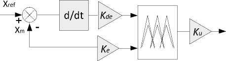
Fig.9. Bloc diagram of PI-IT2FLC.
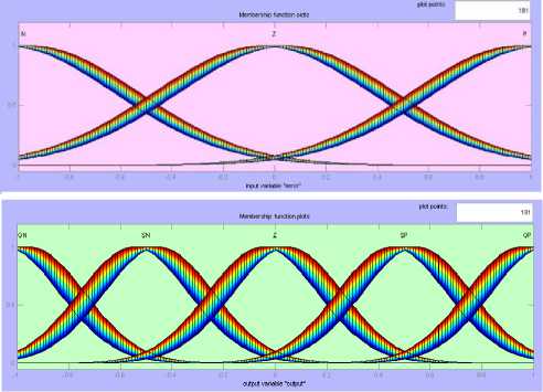
Fig.10. Membership function of error torque and error flux and variation.
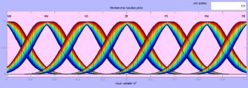
Fig.11. Membership function of error speed and variation
Table 1. Rule Base of Speed IT2FLC
|
U |
e |
|||||||
|
NB |
NM |
NS |
EZ |
PS |
PM |
PB |
||
|
de |
NB |
NB |
NB |
NB |
NB |
NM |
NS |
EZ |
|
NM |
NB |
NB |
NB |
NM |
NS |
EZ |
PS |
|
|
NS |
NB |
NB |
NM |
NS |
EZ |
PS |
PM |
|
|
EZ |
NB |
NM |
NS |
EZ |
PS |
PM |
PB |
|
|
PS |
NM |
NS |
EZ |
PS |
PM |
PB |
PB |
|
|
PM |
NS |
EZ |
PS |
PM |
PB |
PB |
PB |
|
|
PB |
EZ |
PS |
PM |
PB |
PB |
PB |
PB |
|
Table 2. Rule Base of Torque and Flux IT2FLC
|
U |
e |
|||
|
N |
Z |
P |
||
|
de |
N |
NB |
NS |
PS |
|
Z |
NB |
Z |
PB |
|
|
P |
NS |
PS |
PB |
|
-
V. Result and Duscussion
The proposed scheme of the DTC-SVM using three IT2FLCs of DSIM fed by a six-phase inverter (see Fig 12) and the estimation block of torque and stator flux (see Fig. 13) is realized with SIMULINK/MATLAB, while the DSIM’s parameters are define by:
The simulation work consists of two tests for robustness studies:
-
A. Speed and Torque variation
In the first test; the DSIM runs with speed variation values of 100rad / s during] 0-2] s; 157 rad / s for the duration of] 2-4] s; 78.5 rad / s for the duration of] 4 -6] s; -78.5 rad / s for the duration of] 6-8] s. And the torque variation with the sign of the load torque (14 Nm, -14 Nm) for at the periods of (3 s, 7 s).
Table 2. represents the linguistic rule base, which introduces a IT2FLC [18].
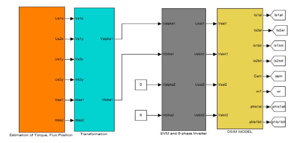
Fig.12. Simulink bloc of DTC-SVM based on IT2FLC of DSIM
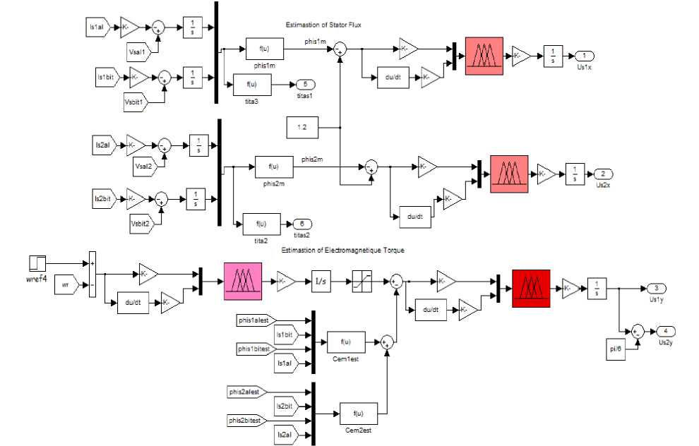
Fig.13. Simulink bloc of the torque and the stator flux estimator
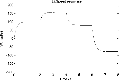
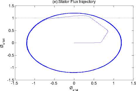
Fig.14. DSIM simulation result with variation of speed and load torque.
Time (s)
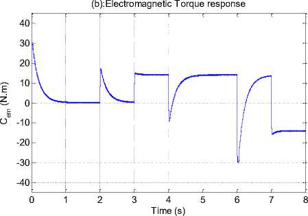
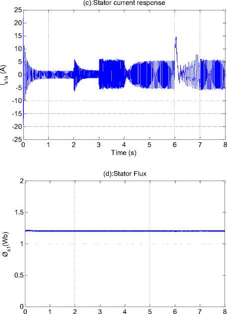
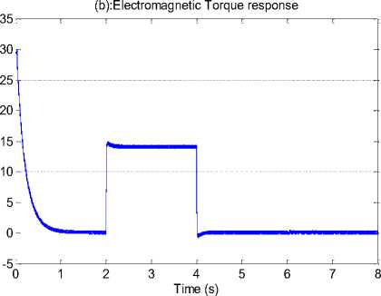
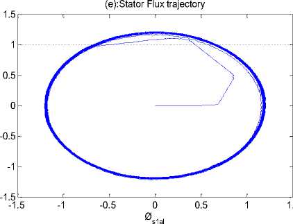
Fig. 14 shows that responses of the change in command speed and load torque for DTC-SVM of DSIM using the proposed IT2FLCs, We note that when the motor starts, the speed reaches its very quickly the desired reference speed (Fig.14 (a)), the mechanical torque increases to reach the peak value (30 N.m) and falls down to be close zero value because the motor running with no load. At we changed the value of load torque to reference, the motor output torque increase to cover this load (Fig. 14 (b)). The response of stator current and amplitude stator flux a produced by motor illustrates in (Fig. 14 (c), (d)). Almost circular flux trajectory with equal amplitudes in both α and β axes (Fig. 14 (e)). This test has for object the study of controller behavior in pursuit and in regulation.
B. Robust control for the internal and external disturbances
The second test in order to confirmed the robustness for control strategy against the external disturbances (represented by the nominal load torque), these variations impose an applied to 14 N.m between (2-4) sec and the internal disturbances (represented by parametric variations), the parametric variations represented by increase of 100% as of the stator resistances 1,2; R s11 = 2* R s1 = 2*R s2 and moment of inertia J 1 = 2 *J at t= 6 s.
(a):Speed response
Time (s)
Ø s1bit Øs1(Wb) I s1a (A) C (N.m)
(c):Stator current response
Fig. 15 shows the behavior of propose scheme when the external disturbances and the parameter variations, Influence of the external disturbances and the parameter variations on the speed, electromagnetic torque, stator current, stator flux response is shown in Fig. 10 (a), (b), (c), (d). This test confirms the effectiveness and flexibility of the proposed control method.
In order to carry out DTC-SVM control of the DSIM using fuzzy logic controllers, the quantitative comparison between T1FLC and T2FLC [16].
The values that are obtained for ISE , IAE and ITAE at the simulation time (8 sec) for the two tests are summarized in Table 3.
Time (s)
Table 3. Performance criteria values for pi, type-1and INTERVAL type-2 fuzzy logic controllers.
|
Tests |
Index |
DTC-SVM-PI |
DTC-SVM-T1FLC |
DTC-SVM-IT2FLC |
|
Test 1 |
ISE |
2.947 |
2.78 |
2.052 |
|
ITAE |
10.62 |
7.149 |
6.514 |
|
|
IAE |
1.764 |
1.666 |
1.53 |
|
|
Test 2 |
ISE |
1.828 |
0.705 |
0.5118 |
|
ITAE |
4.119 |
0.9787 |
0.8437 |
|
|
IAE |
1.778 |
0.6385 |
0.5461 |
From the results obtained in Table 3 it is noted that the values of ISE , IAE and ITAE for the interval type 2 fuzzy logic controller is inferior relative the type 1 fuzzy logic and PI controllers.
DSIM simulations results with the external disturbances and the internal disturbances.
-
VI. Conclusions
In this paper, a new DTC-SVM for a double stator induction machine supplied by a six-phase inverter based on a type-2 fuzzy logic controllers was presented. We have established and simulated a mathematical model of the DSIM and the six-phase inverter and the DTC-SVM using MATLAB-SIMULINK to study the static behavior and dynamics of the DTC-SVM system.
In order to overcome the drawbacks of DTC, we will combine the SVM technique and IT2FLC. It has several advantages: constant switching frequency, excellent response, minimal ripples, low harmonics and good waveform of the stator phase current. The IT2FL controllers offer excellent performance and robustness were verified by simulation.
References DTC-SVM based on interval type-2 fuzzy logic controller of double stator induction machine fed by six-phase inverter
- D. Hadiouche, H. Razik, A. Rezzoug, “On the modeling and design of dual-stator windings to minimize circulating harmonic currents for VSI fed AC machines”, IEEE Trans. Ind. Appl , vol. 4, pp. 506–515, 2004.
- H. Khouidmi, A. Massoum, A. Meroufel “Dual star induction motor drive: modeling, supplying and control”, International journal of electrical and power engineering, vol. 5, pp. 28–34, 2011.
- N. Layadi, S. Zeghlache, A. Djerioui H. Mekki and F. Berrabah, Adaptive RBFNN Strategy for Fault Tolerant Control: Application to DSIM under Broken Rotor Bars Fault, I.J. Intelligent Systems and Applications, vol. 2, pp. 49–61, 2019.
- I. Takahashi, N. Toshihiko, “A New Quick-Response and High Efficiency Control Strategy of an Induction Motor”, IEEE Trans. on Industry Applications, vol. IA-22(5), pp. 820–827, 1986. [Online].
- L. Hellali, S. Belhamdi, L. Benyettou and H. reghioui. Direct torque control of doubly star induction machine fed by voltage source inverter using type 2 fuzzy logic speed controller. AMSE Journals, Series Advances C, vol. 73, N 4, pp 202–207, 2018.
- W. Xueqing, W. Zheng, C. Jian, C. Ming, X. Liang, “Direct Torque Control of Dual Three-Phase PMSM Drives Based on Two-Step Voltage Vector Synthesis SVM”, 8th IEEE International Power Electronics and Motion Control Conf, Asia, 2016.
- C. Z-Liu, C. M-Qu,“ Simulation of SVPWM control strategy for dual three-phase asynchronous motor”, 33rd Youth Academic Annual Conf. Chinese association of automation (YAC), Nanjng, china, 2018, pp. 816-819.
- S. Lu S, K. Corzine,“ Direct Torque Control of Five-Phase Induction Motor Using Space Vector Modulation with Harmonics Elimination and Optimal Switching Sequence”, in Proc. 21th Annual IEEE Conf. Applied Power Electronics, 2006, pp. 195–201.
- L. Jose, P. Azcue, J. Alfeu, F. Sguarezi, R. Ernesto,“ The DTC-SVM Scheme with Takagi-Sugeno Fuzzy Controller for Three-Phase Induction Motor”, 8th International Conf, Fuzzy Systems and Knowledge Discovery (FSKD), 2011, pp. 901–906.
- M. R-Jagan, K S- Manoj, P. K- Subudhi,“ DTC-SVM of Induction Motor by Applying Two Fuzzy Logic Controllers”, International Conf, Electrical, Electronics, and Optimization Techniques (ICEEOT), 2016, pp. 4941–4951.
- I. Aliskan, K. Gulez, G. Tuna, T. V. Mumcu, Y. Altun,“ Nonlinear Speed Controller Supported by Direc Torque Control Algorithm and Space Vector Modulation for Induction Motors in Electrical Vehicles”, ELEKTRONIKA IR ELEKTROTECHNIKA, vol. 6, pp. 41–46, 2013.
- M. Hojat,A. S- Mohammad,“ Controlling the speed and flux of a dual stator winding induction motor using an emotional intelligent controller and integration algorithm”, Turk J Elec Eng & Comp Sci , vol. 26, pp. 3192–3206, 2018.
- L. Bentouhamia, R. Abdessemed, A. Kessal, E. Merabet,“ Control Neuro-Fuzzy of a Dual Star Induction Machine (DSIM) supplied by Five-Level Inverter”, Journal of Power Technologies, vol. 1, pp. 70–79, 2018.
- S. Radhwane, A. Meroufel,“ Rotor field-oriented control (IRFOC) of a dual star induction machine (DSIM) using a fuzzy controller”, Acta Polytechnica Hungarica, vol. 9, pp. 177–192, 2012.
- A. Meroufel, S. Massoum, A. Bentaallah, P. Wira, F. Belaimeche, A. Massoum,“ Double Star Induction Motor Direct Torque Control with Fuzzy Sliding Mode Speed Controller”, Rev. Roum. Sci. Techn. Electrotechn. et Energ, vol. 1, pp. 31–35, 2017.
- K. Vineet, K. P-Rana, N. Sundeep,“ Comparative Study of Type-2 and Type-1 Fuzzy PI Controllers on Sensor Noise Suppression in a Control Loop”, Control Engineering and Applied Informatics CEAI, vol. 19, pp. 20–30, 2017.
- O. Castillo, P. A-Melin, type-2 fuzzy logic, theory and applications, Series. Studies in Fuzziness and Soft Computing. Springer-Verlag :2008, 223.
- H. Hagras,“ Type-2 FLCs: a new generation of fuzzy controllers”, IEEE Compute Intelligence Magazine, vol. 2, pp. 30–43,2007.
- Castillo O, Melin P,“ A review on the design and optimization of interval type-2 fuzzy controllers”, Applied Soft Computing, vol. 12, pp. 1267–1278, 2012.
