DYNAMIC JOINT LOAD TRANSFER EFFICIENCY OF RIGID PAVEMENT

Author: YU Xinhua, WU Xiaochun
Journal: International Journal of Image, Graphics and Signal Processing(IJIGSP) @ijigsp
Article in issue: 1 vol.3, 2011.
Free access
the mechanistic analysis presented in this paper is only the beginning of new approach for understanding the real joint load transfer capability on airport and highway concrete pavements. It gives up the two major assumptions those have been popularly adopted by hundreds of published papers: the load is transferred under a wheel with zero speed and with fixed position. The real load transfer in field is always under wheels with non-zero speed and with varied position at any moment. The objective of this study focuses on quantifying the dynamic effects of a moving wheel while it is crossing a joint on a pavement. The analysis is conducted using a model of two-slab system on Kelvin foundation under a moving wheel with variable speed v, different pavement damping Cs, foundation reaction modulus k and foundation damping Ck. The dynamic joint load transfer efficiency is temporarily and empirically defined by the peak strain ratio LTE(S) on the two sides of a joint. The primary findings include: (1) The higher speed of a moving wheel leads to the higher LTE(S);(2) The larger the pavement damping Cs leads to the higher LTE(S);(3) The numerical ratio c(=LTE(S)dynamic/ LTE(S)static) varies in the range 1 to 2 mainly depending on speed v and damping Cs;(4) The LTE(S)dynamic is not sensitive to foundation reaction modulus k and foundation damping Ck. Further researches are needed for appropriate applications of the new model in practice.
Pavement, joint load transfer efficiency, pavement damping, foundation reaction modulus, foundation damping, strain, deflection
Short address: https://sciup.org/15012083
IDR: 15012083
Text of the scientific article DYNAMIC JOINT LOAD TRANSFER EFFICIENCY OF RIGID PAVEMENT
Published Online February 2011 in MECS
-
A. Fundamental differences exist between the assumptions in most joint models for pavement design and evaluation in the field reality
Hundreds of published papers are available to model the joint load transfer mechanism in the past decades. They have been widely used in specifications for concrete pavement design. They have also provided significant contributions for making a concrete pavement long-lasting, low-cost and easy maintenance through fundamental studies. All the popularly used models were developed based on static analysis: the speed of wheel is assumed zero. Falling Weight Deflectometer (FWD) has been played major role in field practice for evaluating the joint load transfer capability of a concrete pavement before its major rehabilitations. The joint load transfer capability is evaluated by the ratio of deflections on the two sides of a joint due to a circular FWD load entirely dropped on one side of a joint. The load is similar to a dynamic impulse, but the position is tangentially fixed at the joint.
Significant differences exist between above assumptions and the reality in field. The real load transfer through a joint is under moving wheels with different speeds which are far from static as assumed in the existing models. The position of the wheel changes at any moment rather than the fixed position adopted by FWD machine in pavement field evaluation. Joints are the weakest locations in a concrete pavement and almost all cracks are observed initiated from a joint. The true maximum stress parallel to and at a joint needs to be known when a vehicle is crossing the joint. If a joint in which the LTE (S) defined by current static model has been significantly reduced its load transfer capability is predicted almost equivalent to a free edge. Therefore, the ratio between the maximum stress at the unloaded side and maximum stress at the free edge ( LTE ( σ ) = σ U / σ F ) has been used by FAA as a parameter to define the LTE (S) of a joint. If the concrete material properties on the two sides of a joint are assumed the same, the strain based LTE (S) ( ε U / ε F ) should be the same to LTE ( σ ) at a joint and it is used in this paper for convenience of engineers who are familiar with different unit systems. An assumption σ U + σ L = σ F , where σ L is the maximum stress at the loaded side of a joint, has been recognized and employed in published papers by some pavement engineers for decades. The theoretical proof and the valid conditions of above relation including w U + w L = w F , where w is deflection, can be found in Guo 2003 [1]. The deflection rather than stress ratio has been much more popularly used in practice because the deflection can be quickly and easily measured using FWD. Based on above fundamental study, the maximum deflection at the free edge can be estimated without entirely cutting the joint in field. Rather, it can be obtained by simply adding the two deflections on the two sides of a joint if the slab curling can be negligible.
LTE (S) = 25% has been used in FAA design specifications for many years [2]. Or, if the maximum tensile stress is 4 MPa under a load at a free edge, the critical stress = 3 MPa will be used for design. If the LTE (S) is assumed 40%, the critical stress used for design should be 2.4 MPa that would be 20% lower than the critical stress by assuming: LTE (S) = 25%. The 20% difference in critical stress would lead to significantly different slab thicknesses for design by all existing design models. For approaching the objective in priority in concrete pavement research - high performance and low cost, we need to know the true critical stress at the joints under real traffic in different environments. Or, it is necessary to evaluate the effects of difference between model assumptions and the reality in filed. The beginning but most economic step to evaluate is to conduct a mechanistic analysis using different assumptions: dynamic vs. static as shown in this paper. The effects on LTE (S) must be contributed by many parameters used in the dynamic model. It is easy and also economic to identify which parameters are more important than the others to lead to the difference.
More than 15-year field data at Denver Airport indicate that the low LTE ( w ) defined by existing models did not lead to early cracks
Asphalt Shoulder
|
g Al |
? A2 |
P A3 |
9 A4 м |
|
|
85.3 |
82.9 |
85.7 |
83.6 |
|
|
m B1 |
8 B2 |
Й B3 |
8 B4 |
|
|
CO |
co |
|||
|
55.7 |
66.5 |
65.3 |
64.8 |
|
|
63.4 |
||||
|
C1 |
G2 |
C3 |
C4 |
T<-10°C |
|
81.2 |
57.5 |
|||
|
84.1 |
. North |
|||
|
DI |
Й D2 |
co D3 |
5 D4 |
Im |
|
kJ |
The center line of Runway 16L/34R ^
Transfer coefficients (%)
(a)April 1997
Asphalt Shoulder
|
S A1 TO |
S A2 86 |
g A3 84 |
S A4 83 |
2 |
|
5 bi 66 |
5 B2 66 |
Й 83 7W27J |
s B4 70 |
5 |
|
C1 |
C2 S0f45| |
62(22) C3 87Г37) |
04 |
T=22°C |
|
D1 i |
■5 02 |
89(38) S D3 |
2 D4 |
North ^ |
The center line of Runway 16U34R □
Transfer coefficients (%)
(b) August 1997
Figure1. Typical LTE ( w ) Measured at Denver Runway 16L/34R (The numbers in parenthesis are LTE (S))
More than fifteen-year pavement response and performance data have been collected at the FAA instrumented PCC pavement test site at Denver International Airport. Many of them are available for public in WEB site Figure.1(Dong et al, 2002[3]) shows the values of LTE(w) for 20 slabs (12.9 – 18.2%) in April 1997 and (84-88%) in August 1997. Total 200 slabs have been continuously surveyed by WES, US Army Engineering Corps since the runway was built in 1992 up to the latest survey in 2008. Slabs D1 to D4 are the slabs by the pavement center line. Every three of the four transverse joints are saw-cut and their LTE values were always significantly different in cold and hot weathers. Every one of the four joints was doweled and their LTE values were similar in the two weathers. Following are major findings:
Denver Airport Runway 16L/34R has been operated for more than 15 years. Among them approximately 5 years were in cold weather. Therefore the values of LTE ( w ) were very low in a long period and the load transfer efficiencies defined by current FAA were lower than 5%, or, the maximum stresses on the loaded side were 95% even higher than that of the critical free-edge stress) [2].
Runway 16L/34R has been operated for very heavy aircrafts such as B-747, B-777 for more than 15 years. Most body gear loads were driven on the lane by the runway center line (on the slabs D1-D4). Longitudinal crack that is perpendicular to the transverse joint has been observed only on one of the 20 slabs in the lane. If the static model can appropriately predict the crack risk due to significant reduction of LTE (S), more longitudinal cracks would have been observed.
Comparison of the distresses and values of PCI between the trafficked (such as slabs D1-D4) and none trafficked area (such as slabs A1 – A4) shows that there was no significantly differences. That supports above finding: the low value of LTE (S) seems not increase the critical edge stress at the joint as predicted by the current static models.
-
B. Brief review of existing joint models
A very detailed review of the researches related to doweled bar system can be found in Maitra et al [4] in which most published papers have been referenced, including [5]-[10]. However, what are the advantages and disadvantages (even some theoretical errors) of each model, why some models have been stopped using and replaced by the others are not available in the paper. Another paper briefly reviewing the joint modeling development history based on finite element method was published recently by Guo[11].This paper focuses on several key progresses in the joint modeling development, describes the major contribution and deficiencies even fundamental error of each model when it was developed. It also explains why some errors must be getting rid off. This would be helpful for new investigators and program users to avoid the use of incorrect models those are currently still installed and available for users in some popularly used programs.
-
C. What is new in this paper?
This paper might be the one of the earliest trials to theoretically analyze the joint load transfer capability based on dynamics. Many projects, under FAA and FHWA have been completed in past decades (some are still going on) for studying how many percentage of a wheel load can be transferred through a joint during the pavement service. Most of the results were obtained by using the two major assumptions mentioned above. How accurate and reliable the results are? The field data in Denver test runway did not completely support the critical stress at the joint predicted by the static model. The analysis presented in this paper is only a beginning of new approach for understanding the real joint load transfer capability on airport and highway pavements. It seems that the significant difference exist between the results predicted by the two types of models. Further, above two popularly adopted assumptions in static analysis can also be simulated in the dynamic model by setting the moving speed, damping and mass approaching to zero. Therefore, the reliability of the results based on dynamic analysis can be qualitatively checked by existing static models.
-
II. M ETHODOLOGY
-
A. Model
Generally, a rigid pavement structure is modeled as a single- or multi-layered slabs resting on an elastic foundation. For simplicity, we take the following assumptions:
-
• Material for each layer is in homogenous and linear elastic;
-
• Under moving load the pavement structure damping effect shall not be omitted;
-
• The function of aggregate interlock or dowel bar embedded can be reflected by a set of joint shearing springs;
-
• Kelvin foundation can be used to simulate the behavior of the sub-grade.
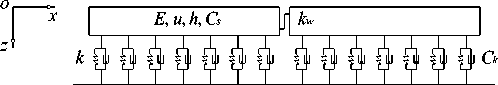
A model of two-slab system on Kelvin foundation for dynamic effects analysis of concrete pavement structure is illustrated in Figure 2.
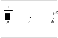
As shown in Figure 2, L , B , h are the length, width and thickness of pavement slabs, E , u , C s are the Young’s modulus, Poisson’s ratio and pavement damping, and k , C k are the foundation reaction modulus and foundation damping respectively, k w is the joint shearing spring stiffness, P= 57.6kN is the load applied on the pavement slab with area 0.2m×0.2m moving at the speed of v , letters i (interior), e 1 , e 2 (near edges) represent the measuring locations of strains and deflections in pavement slabs; g is the width of joint, l b is the distance of points e 1 , e 2 to edges.
(a) Cross section view
g

distance from edge lb e2
B
(b) Plane view
Figure2. Model of two-slab system
The governing differential equations of pavement structure considering dynamic effects under moving load are given below [12]:
D V2V2 w+C —+kw + ph ^-w = P5( x - vt) dt dt2
Where: D is the flexural rigidity of pavement slabs, D = Eh 3 /12(1- u 2 ); w is the vertical deflection of pavement slab; C is the structure damping including pavement damping and foundation damping; k is the reaction modulus of sub-grade; ρ is the mass density of pavement slab; P is the moving load; δ ( ) is the Dirac function.
-
B. Solution method and ERROR
The finite element method is employed to obtain the numerical results of model established above, here we select general finite element software ANSYS [13] due to its powerful and reliable functions. As per pavement slab, Shell63 element is used, for the joint shearing spring and Kelvin foundation the Combin14 element is applied.
To obtain the dynamic responses of pavement slab under moving load, a so-called direct integration method (Full-Method) is employed (see equations 2)[12].
[M]{*}+[C]{'^+[K]{< ■F}
(2a) [ C ] = [ C, ] + [ C j (2b)
Where: [ M ] is the mass matrix of pavement structure; [ C ] is the damping matrix of pavement structure; [ K ] is the stiffness matrix of foundation; { F } is the column vector of external force; [ C s ] is the pavement damping matrix; [ C k ] is the foundation damping matrix.
As we know, the selections of proper time/load step and element sizing are crucial for a transient analysis, however, with reference to documents [12],[14], time step ∆ t ≤∆ t cr = T n /π ( T n is the minimum natural frequency period of a concrete pavement structure) and element size 0.1m will be selected for analysis.
-
III. I NFLUENCES OF MATERIAL DAMPING AND MOVING
SPEED
A. Parameters
Taking a typical cement concrete pavement structure for transient analysis, the parameters are listed in Table I .
TABLE I .
PARAMETERS
|
L /m |
B /m |
h /m |
l b /m |
E /MPa |
u |
|
5 |
4 |
0.2 |
0.1 |
30000 |
0.15 |
With reference to documents [6-8], for joint load transfer by dowel bars embedded we take k w =3000 MN/m 3 ; according to documents [13-14], we assume the pavement damping C s =0.008~1.2MN·s/m 3 ; regarding foundation parameters, we suppose the foundation reaction modulus k= 40 MN/m 3 , and the foundation damping C k =0.002~0.2 MN·s/m 3 .
B. Strains AND DEFLECTIONS in pavement slabs
For simplicity, the foundation damping C k is assumed to be 0 at the moment, thus the Kelvin foundation is degraded into Winkler foundation. As such the effects of the pavement damping and the load moving speed on the strains in pavement slabs are discussed. Pertaining to the effect of foundation damping C k , it will be given in the following section.
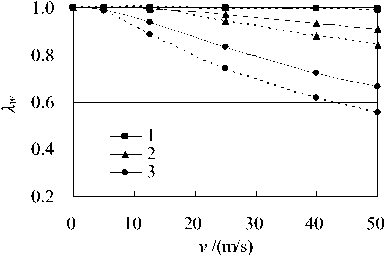
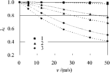
To clearly describe the effects of pavement damping and the load moving speed on the strains and deflections in pavement slabs, a strain ratio λ ε and a deflection ratio λ w are defined as follows.
(b) deflection
Figure 3. Diagrams of λ ε , λ w versus moving speed v (1- C s =0.008MN·s/m3, 2- C s =0.4MN·s/m3, 3- C s =1.2MN·s/m3)
Due to the presence of the pavement damping C s , when the load moving speed v ≠0, we observed that the appearing time of peak strain at a point on the pavement slab is somewhat behind the time that the moving load just acted on it. However, a variable of time variation Δ t or horizontal displacement Δ X (=Δ t ∙ v ) can be used to quantitatively describe the time lag effect. The schematic of time lag of peak strain at a point on the pavement slabs is shown in Figure 4.
^ dynamic
ЛЕ =-------, static
к
dynamic
static

Here ε dynamic , w dynamic are the maximum strain and deflection in dynamic analysis or measurement, ε static , w static are the strain and deflection in static analysis or measurement.
The diagrams of strain and deflection ratios λ varying with the load moving speed v are shown in Figure 3, in Figure 3 the continuous lines denote the strain or deflection ratios for interior point i , whereas the dotted lines represent the strain or deflection ratios for transverse edge point e . It can be seen that with increase of the load moving speed v the strain and deflection ratios come down, and the larger the pavement damping C s the bigger the variation of strain and deflection ratios. Also, there existed some difference of strain and deflection ratios between interior point i and transverse edge points e 1 , e 2 , but their trends varying with the load moving speed v are similar.
(a) strain
g
L
|
v |
distance from edge l b |
|
|
----*- |
||
|
■ 0 © |
||
|
P i e 1 |
e 2 |
P
v
ε _e1 , v ≠0
Δ t
Figure4. Schematic of time lag of peak strain at point e 1
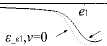
The diagrams of horizontal displacement Δ X versus the load moving speed v under different pavement damping C s are shown in Figure 5. Obviously, it can be seen that with increase of the load moving speed v , the horizontal displacement Δ X rise up, the larger the pavement damping C s , the bigger the horizontal displacement Δ X .
-
Figure5. Diagrams of Δ X versus moving speed v
-
(1- C s =0.008MN·s/m 3 , 2- C s =0.4MN·s/m 3 , 3- C s =1.2MN·s/m 3 )
-
C. Joint load transfer efficiency
Normally, the joint load transfer efficiency can be expressed based on deflection, as.
LTE ( w ) = w unloaded x 100% (4)
w loaded
Where: w unloaded , w oaded are the deflections on unloaded and loaded slabs respectively.
The joint load transfer efficiency may also take the following empirical form [15-17]:
v / m/s
Figure7. Diagrams of LTE (S) versus moving speed v ( k w =3000 MN/m 3 ) (1- C s =0.008MN·s/m 3 , 2- C s =0.4MN·s/m 3 , 3- C s =1.2MN·s/m 3 )
LTE ( S ) =---- " unloaded ----x 100%
^ loaded + ^ unloaded
£
_ mloeded x100% loaded unloaded
Where: σ loaded, ε loaded are the stress and strain in loaded slab as specified in the time history; σ unloaded , ε unloaded are the corresponding stress and strain in unloaded slab as specified, respectively.
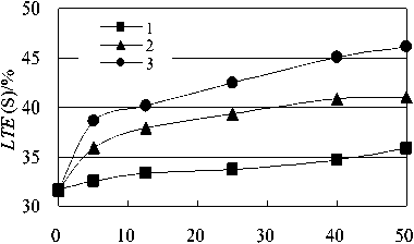
Under moving loads, the measured strains in loaded and unloaded slabs varying with time obtained from airfield pavements at Federal Aviation Administration’s (FAA) National Airport Pavement Test Facility (NAPTF) are shown in Figure 6.
Figure6. Diagrams of measured strains ε versus time (from FAA) [15]
When calculating the joint load transfer efficiency LTE (S), the strains ε unloaded , ε loaded in loaded and unloaded slabs may be acquired properly by referring to Figure 7, the joint load transfer efficiency estimated based on the strains is as follows:
LTE(S) _----^unloaded----x 100%
£ + £ loaded unloaded
0.042 _----------x 100% _ 43.3%
0.055 + 0.042
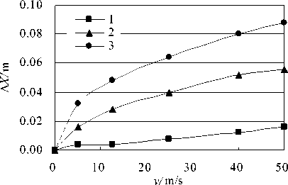
The diagrams of joint load transfer efficiency LTE (S) varying with the load moving speed v under different pavement damping C s are shown in Figure 7.
We can see from Figure 7 that with increase of the load moving speed v the joint load transfer efficiency LTE (S) go up, and the larger the pavement damping C s the bigger the joint load transfer efficiency LTE (S), vice versa.
It should be noted that in static viewpoint the essence of joint load transfer is due to the existence of a so-called joint shearing spring stiffness k w ; when taking into account the dynamic effects of pavement structure, it is no longer true to represent the joint load transfer capacity solely by using joint shearing spring stiffness k w .
Figure 8 is a diagram of the joint load transfer efficiency LTE (S) varying with the load moving speed v when k w =0.
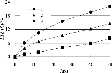
Figure8. Diagram of LTE (S) versus moving speed v ( k w =0) (1- C s =0.008MN·s/m 3 , 2- C s =0.4MN·s/m 3 , 3- C s =1.2MN·s/m 3 )
Although k w =0, the joint load transfer efficiency LTE (S) no longer remains 0 except for the case of v =0, and goes up with increase of the load moving speed v , the reason is that the strain ε unload ≠0 due to the presence of pavement damping C s , thus LTE (S) ≠0. However, when we are talking about the joint load transfer efficiency, the pavement damping C s and the load moving speed v shall be mentioned, thus, the joint load transfer efficiency LTE (S) is a conditioned index to evaluate the joint load transfer capacity.
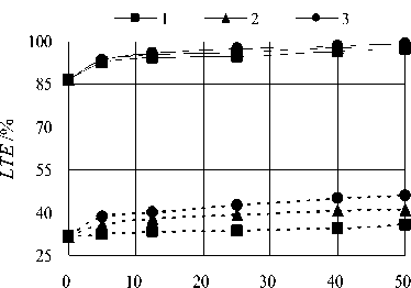
A comparison of the strain-based joint load transfer efficiency LTE (S) and deflection-based joint load transfer efficiency LTE ( w ) varying with the load moving speed v is illustrated in Figure 9, the continuous lines denote the deflection-based joint load transfer efficiency LTE ( w ), and the dotted lines stand for the strain-based joint load transfer efficiency LTE (S).
v /m/s
Figure9. Diagrams of LTE versus moving speed v (1- C s =0.008MN·s/m 3 , 2- C s =0.4MN·s/m 3 , 3- C s =1.2MN·s/m 3 )
Since the deflection-based joint load transfer efficiency is widely employed across the world, and the testing equipment such as Benkelman beam and Falling Weight Deflectometer (FWD) are much easily available. However, it is possible to find out the relationship between LTE (S) and LTE ( w ).
-
IV. I NFLUENCES OF FOUNDATION
-
A. Foundation reaction modulus k
Other parameters remain unchanged, under different foundation reaction modulus k , the joint load transfer efficiency LTE (S) are listed in Table H
TABLE П .
LTE (S) ( C s =0, v =5m/s)
|
k /MN/m3 |
static LTE (S) /% |
dynamic LTE (S) /% |
|
40 |
31.7 |
38.6 |
|
60 |
30.6 |
38.0 |
|
90 |
29.3 |
37.2 |
When the foundation reaction modulus k increases from 40 to 90 MN/m 3 , both the static and dynamic LTE (S) come down 7.6% and 3.6% respectively, obviously the influence of foundation reaction modulus k on LTE (S) is not significant, therefore, it is appropriate to analyze the joint load transfer efficiency LTE (S) only taking a fixed foundation reaction modulus k .
-
B. Foundation damping C k
When the parameter of foundation damping C k ≠0, the foundation complies with Kelvin assumptions, other parameters remain unchanged, under different foundation damping C k , the joint load transfer efficiency LTE (S) are given in Table Ш .
Table Ш .
LTE (S) ( C s =0, v =5m/s)
|
C k /MN·s/m |
ε loaded /10-6 |
LTE (S) /% |
|
0.002 |
238 |
45.5 |
|
0.02 |
239 |
46.0 |
|
0.2 |
239 |
45.9 |
The influence of foundation damping C k on LTE (S) is quite small, and therefore can be neglected.
-
V. CONCLUSIONS
Considering the dynamic effects of pavement structure, through some examples, the strains and deflections at points as specified and corresponding joint load transfer efficiency are discussed, and the conclusions are drawn as follows:
-
1. The peak value of the specified strains and deflections in unloaded slabs drop and its appearing time lags due to the presence of pavement damping C s ;
-
2. With increase of the load moving speed v , the joint load transfer efficiency LTE (S) rises up gradually;
-
3. The larger the pavement damping C s , the bigger the variation of the peak strains, the longer the lag time, and the higher the LTE (S);
-
4. The ratio c (= LTE (S) dynamic / LTE (S) static ) varies in the range 1.0 to 2.0 mainly depending on variables v and C s ;
-
5. The influences of foundation reaction modulus k and foundation damping C k on the joint load transfer efficiency are not significant, and therefore can be neglected.
A CKNOWLEDGEMENT
This research is supported by Yoh Foundation from the United States of America, a special thanks is due to Dr. James Yoh. We are also grateful of Federal Aviation Administration’s (FAA) National Airport Pavement Test Facility (NAPTF) for permission of use of their full scale testing data of airfield pavements.
References DYNAMIC JOINT LOAD TRANSFER EFFICIENCY OF RIGID PAVEMENT
- Guo, Edward.H (2003). “Proof and Comments on an Extensively Used Assumption in PCC Pavement Analysis and Evaluation”, ASCE Journal of Transportation Engineering, Vol. 129, No.2, March/April 2003.
- FAA, 2009, Airport Pavement Design and Evaluation AC 150/5320-6E, Aug. 18, 2009.
- Dong, M and G. Hayhoe, 2002 “Analysis of Falling Weight Deflectometer Tests at Denver International Airport”, FAA Technology Transfer Conference, 2002.
- Maitra, S. R., K. S. reddy adn L.S. Ramachandra, “Load Transfer Characteristics of Dowel Bar System in Jointed Concrete Pavement”, Journal of Transportation Engineering, Vol. 135, No. 11, November 1, 2009, page 813 – 821
- A.M Tabatabaie. Structural analysis of concrete pavement joints [D]. Illinois: University of Illinois at Urbana -Champaign, 1978
- Y.T. Chou, and Y. H. Huang. A computer program for slabs with discontinuities, Proceedings, International Air Transportation Conference, 1979, 1:121-136
- T. Nishizawa, T. Fukuda, S. Matsumo, A refined models of doweled joints for concrete pavements using FEM analysis. [C]//Proceedings, 4th international concference on concrete pavement Design and Rehabilitation, Purdue University, 1989:735-745
- A.M Ioannides, and G.. T. Korovesis, Aggregate interlock: a pure shear load transfer mechanism. TRR, 1990, 1286:14-24
- A. M. Ioannides, G. T. Korovesis, Analysis and design of doweled slab-on-grade pavement systems [J], Transportation Engineering Journal, ASCE, 1992, 118(TE6): 745-768
- H. Guo, J. A. Sherwood, M. B. Snyder Component dowel-bar model for load transfer systems in PCC pavements [J].Journal of Transportation Engineering, ASCE, 1995, 121(3): 289-298
- Guo, E. “Joint Modeling for JPCP, Success and Pending Problems”, Proceeding of BCR2A 2009 International Conference, page 531-542, edited by Erol Tutumluer & Imad L. Al-Qadi.
- A.K. Chopra, Structural Dynamics [M]. Beijing: Tsinghua University Press, 2009.
- ANSYS Inc., ANSYS Theory Reference 10.0[R], 2005
- Jingbo LIU, Xiuli DU. Structural Dynamics [M].Beijing: China Machine Press, 2005(in Chinese).
- AA, 2009, Airport Pavement Design and Evaluation AC 150/5320-6E, Aug. 18, 2009.
- Wadkar, A, A Zapata and L Musumeci, 2010 “Analysis and Evaluation of Load Transfer Efficiency of Rigid Airfield Pavements”, Presentation in Data Analysis Working Group Forum, TRB 2010.
- Wadkar,A, A. Norton, C. Tomlinson, A. Zapata, L. Musumeci, E.H. Guo, D.B. Cleary, Y. A. Mehta 2010 “Load Transfer Efficiencies of Rigid Airfield Pavement Joints Based on Stresses and Deflections”.
