Edge Detection System using Pulse Mode Neural Network for Image Enhancement

Author: S.Jagadeesh Babu, P.Karunakaran, S.Venkatraman, I.Hameem Shanavas, T.Kapilachander
Journal: International Journal of Image, Graphics and Signal Processing(IJIGSP) @ijigsp
Article in issue: 3 vol.4, 2012.
Free access
Edge detection of an image reduces significantly the amount of data and filters out information that may be regarded as less irrelevant. Edge detection is efficient in medical imaging. Pulse mode neural networks are becoming an attractive solution for function approximation based on frequency modulation. Early pulse mode implementation suffers from some network constraints due to weight range limitations. To provide the best edge detection, the basic algorithm is modified to have pulse mode operations for effective hardware implementation. In this project a new pulse mode network architecture using floating point operations is used in the activation function. By using floating point number system for synapse weight value representation, any function can be approximated by the network. The proposed pulse mode MNN is used to detect the edges in images forming a heterogeneous data base. It shows good learning capability. In addition, four edge detection techniques have been compared. The coding is written in verilog and the final result have been simulated using Xilinx ISE simulator.
Edge detection, Pulse mode, Synapse multiplier, Floating point operation
Short address: https://sciup.org/15012251
IDR: 15012251
Text of the scientific article Edge Detection System using Pulse Mode Neural Network for Image Enhancement
Published Online April 2012 in MECS DOI: 10.5815/ijigsp.2012.03.07
The goal of edge detection is to mark the points in a digital image at which the luminous intensity changes sharply. Sharp changes in image properties usually reflect important events and changes in objects included in the image. Edge detection preserves the important structural properties of an image and acts in a similar way as a filter do for irrelevant data. Owing to the function approximation capabilities of neural networks, artificial neural networks can be used efficiently, instead of conventional edge detection approaches, such as: Laplacian method, Canny operator, etc... The same network hardware can be used by modifying synaptic weight, for approximating other image processing function.
Multilayer neural networks (MNNs) are used for applications taking high-resolution inputs. Therefore, if the range of the weights is small, learning is not possible with high input resolution. The proposed system uses simple floating point number to represent the synaptic weight values while the network input and output level are represented by the frequency of the pulse signal. Using the floating point operation , synaptic weights cover a very wide range thus providing MNN applications with high precision.
This work implements a new neural network based edge detection system acting as a canny operator. An improved digital pulse mode neuron was used with the following features:
-
• Floating point operation as its activation function;
-
• Activation function is smooth;
-
• Accompanying synapse multiplier is very simple.
Modeling complex functions with neural networks, increases dramatically the neural network size, stating the use of more hardware resources. Accordingly, the design of a compact neuron become indispensable in neural network implementation. The whole system is implemented on a virtex II field programmable gate array (FPGA) platform and the neuron characteristics are tested experimentally.
The remainder of this paper is organized as follows: Section II introduces the neural network based edge detector design principle. Section III describes the general architecture of pulse multilayer neural network. An improved architecture based on floating point operations in the activation function is proposed in section IV. Finally, experimental results are presented in Sections V, followed by conclusion in Section VI.
-
II. NEURAL NETWORK BASED EDGE DETECTION DESIGN PRINCIPLE
In this work, canny operator is used as an edge detector. According to Canny, the optimal filter can be efficiently approximated using the first derivative of a Gaussian function . A multilayer neural network was learning the canny operator. For validation and test, a series of image data base was used. Each one is formed by a particular set such as hands (for biometry applications), mammography images (for breast cancer classification) and simple images for validation and tests such as dinosaur images, etc,... Each set is subdivided into two classes, one is for the network learning, and the other is for test of network generalization. Training of input layer is obtained by 3x3 mask sweeping the sample images. The network output is taken as the middle point in the image, resulting from the canny operator. Back propagation algorithm is applied for each image data base. After testing the generalization procedure task, in each case, we memorize the parameters for further application. Once, we have the different network parameters for each set of images, we use them accordingly in forward operation [1].
neurons in the upper layer through feed forward connection network. Inspired by biological model, pulse mode network operations uses frequency to represent the signal levels. Synaptic weighting is therefore a frequency multiplication. Activation function is a saturation function with nonlinear characteristics, being at best programmable in an active way[2].
-
IV. PROPOSED EDGE DETECTION OPERATION WITH SINGLE CANNY BLOCK STRUCTURE
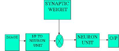
Figure 1.Architecture of the Edge detection operation with single canny block
In figure 1 ,the test image is converted into binary format by using MATLAB. Then the binary values are multiplied with that of the weight function and forwarded to that of the neuron unit the neuron unit provides the detected edges as output.
-
A. Floating Point Activation Function
The synaptic weight is represented using floating point representation as follows[1]
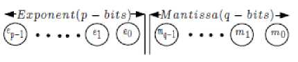
Figure 2. Floating point process
-
B. Synaptic Unit
The synaptic unit mainly performs the operation of multiplying the weights with that of input image which is in binary format.
-
III. GENERAL ARCHITECTURE OF PULSE MODE NEURAL NETWORKS
The operation of the MNN is divided into two phase, learning phase and retrieving phase. During learning phase,weights are adjusted to perform a particular application. During the retrieving phase, data from neurons of a lower layer is propagated forward to
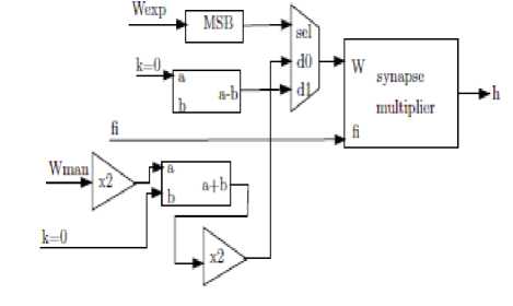
Figure 3.Synaptic Unit
-
C. C. Synaptic Multiplier
This block mainly performs the function of concatenation. The weights which are split into mantissa and exponential part are multiplied with the inputs. The resulting result is arranged in the concatenation block. The output of the block is fed into that of the neuron unit. The block diagram of the synaptic multiplier is shown in figure 4.
The neuron unit block diagram is given in figure 5.
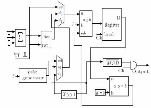
Figure 5. Structure of Neuron Unit
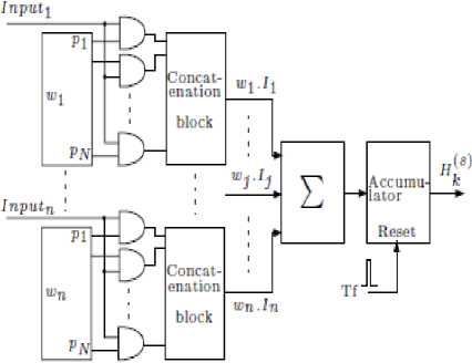
Figure 4.Synaptic Multiplier
-
D. D. Neuron Unit
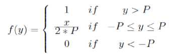
In the neuron unit, weighted neuron outputs from the lower layer are summed up and the outputis generated using the activation function. Every period of Tf , the sum of input weight values from synapse multipliers H ( s ) k is fed to the register, where it is accumulated[3]. When R is positive, + P is subtracted from the register and the output pulse of ramp function neuron is generated with a frequency equal to one. Afterwards, the content of the register alternate positive and negative and the gradient of the change is P .
When -P ≤ H ( s ) k ≤ + P , the content of the register becomes positive or negative alternately. Therefore, the activation function of the proposed neuron uses floating point operation is ramp function, which is given by
-
V. PROPOSED ARCHITECTURE FOR EDGE
DETECTION OPERATION WITH 32
CANNY BLOCK
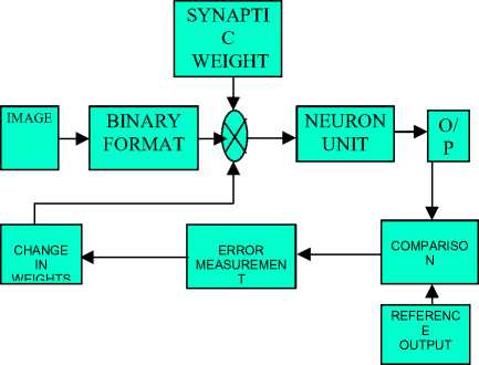
Figure 6. 32 Canny Block Structure
The concept of edge detection is extended to 32 canny blocks by using single canny block as reference. The two main principles used are,
-
• BPN OPERATION
-
• GENERALIZED DELTA RULE
Back propagation algorithm aims at finding the change in weights by backtracking the obtained output to the input. The generalized delta rule states that the new updation of weights is given by the sum of the original weight and two times the difference of the original output and the difference output[4][5].
The rule is given by,
w(t+1) i = w(t) + 2(d k -y k )x ki (2)
where,
w(t+1) I – Updated Weights
w(t) - Original Weight dk - Original Output
-
y k - Reference Output
-
x ki - Corresponding Input
-
VI. MODULES FOR 32 CANNY BLOCK
-
A. Training of Neural Network
The block diagram for implementation of 32 canny block is shown in figure.6,
The pixels of the re-sized image are given as binary input to the neural network. Based upon the neural network trained using single canny block, the edges corresponding to the input are produced at the output.
The weights of the calculated value and the reference value are compared and the positive or the negative difference between the two values is calculated. Based upon the error calculated the hidden and output layer weights are updated and the updated values are forwarded to the input. The process is repeated for 32 blocks in a loop fashion so that the error gets totally eliminated or reduced to a very small amount. The resulting output pixel value represents the edges of the overall image[6].
B.Updation of Hidden Layer Weights
The input pixel values are applied to the neural network unit which is denoted as xp and is represented as[7], xp = (xp1,xp2,…,xpn) (3)
The net input to the hidden layer units is given by, netpjh = si=1N Wjihxpi + j (4)
W jih - weight of the corresponding hidden layer unit xp i - corresponding input layer unit 9 jh - bias term (value = 1)
The outputs from the hidden layer is given by, ipj = fjh(netpjh)(5)
f jh - functional term of hidden layer
The error at the hidden layer is given by,
5pjh = fjh(netpjh) SkSpko wyo
5pko - error at the output layer wkjo - weight of the corresponding output layer unit
The updated weights of the hidden layer is given by,
Wjih(t+1) = Wjih(t) + pS^ x(7)
w jih (t) - present weight of the hidden layer unit П - learning parameter (0.05 to 0.25) X i - corresponding input unit
C.Updation of Output Layer Weights
The net input to the output layer units is given by, netpko = Sj=1N wkioipj + 9ko wkio - weight of the corresponding output layer unit 9ko - bias term (value = 1)
The results at the output layer is given by, opk = fko(netpko)(9)
f ko - functional term of output layer
The error at the output layer is given by,
5pko = (ypk - opk)(10)
ypk - present output value o pk - reference output value The updated weights of the output layer is given by,
Wyo(t+1) = w/Ш + n5pko ipj wkjo(t) - present weight of the output layer unit ipj - output at the hidden layer
The updated hidden and output layer weights are forwarded to the input units. Based upon the new weights the above process looped around the network to calculate the edges[8].
D.VLSI Implementation
The training of the neural network is based upon the above mathematical formulation and the coding is written in verilog. The output edges is in the form of pulse signals[9].
-
VII. EXPERIMENTAL RESULTS
Based upon the comparison techniques above discussed a sample image has been taken and the four edge detection techniques are applied on the image. The original reference image is shown in Figure 7.

Figure 7.Original reference Image
The output image of the Sobel edge detection technique is shown below. From the figure 8 we can infer that the noise performance is poor and the edge thickness is high.

Figure 10. Robert edge detection
The output image of the Canny edge detection technique is shown i below. From the figure we can infer that this technique has best noise performance and edge thickness is low. Hence canny edge detection is best suitable for neural network implementation.

Figure 8.Output of Sobel Image Technique

Figure 11. the Canny edge detection
The output image of the Prewitt edge detection technique is shown below. From the figure 9 we can infer that the noise performance is stable and the edge thickness is high.

Figure 9. Prewit edge detection Technique
TABLE .1 SUMMARY OF RESULTS
|
Techniques |
Noise Performance |
Edge Thickness |
|
Sobel |
Poor |
high |
|
Prewitt |
Stable |
high |
|
Robert |
Stable |
medium |
|
Canny |
best |
low |
The output for edge detection using single canny block is shown in fig. The 9*9 image in the binary format is entered as input and the horizontal component, vertical component, absolute functions of horizontal and vertical component and detected edge values are produced at the output.
The output image of the Robert edge detection technique is shown below. From the figure 10 we can infer that the noise performance is stable and the edge thickness is medium.

The verilog coding has been implemented targeting chip design and the device utilization and timing summary are shown below in tables below.
TABLE 2: COMPARISON OF RESULTS
|
Parameter |
Value for 32 Canny block |
Value for Prewit edge technique |
Value for Robert edge technique |
|
Maximum Frequency |
30.895 Mhz |
81 out of 3072 |
nil |
|
Minimum input arrival time before clock |
23.641 ns |
139 out of 6144 |
nil |
|
Maximum output required time after clock |
8.289 ns |
72 out of 166 |
nil |
|
Maximum combinational path delay |
13.837 ns |
78096 Kb |
30.729 ns |
The verilog coding for 32 canny block edge detection has been implemented targeting chip design and the result are summarized below .
The output for edge detection using single canny block is shown in fig 12. The 3*9 image in the binary format is entered as input. Data strobe is set to low value and the mode strobe, read/write bus is set to a high state. After giving the run command the detected edges are displayed.

Figure 12. Output of single canny block
TABLE 3.SYNTHESIZED RESULTS OF 32 CANNY BLOCK STRUCTURE
|
Parameters |
Value |
|
No of Slices |
2936 out of 3072 |
|
No of Slice Flip Flops |
838 out of 6144 |
|
No of 4 input LUT’s |
4825 out of 6144 |
|
No of Bonded IOB’s |
12 out of 166 |
|
No of TBUF’s |
8 out of 3072 |
|
No of GCLK’s |
1 out of 4 |
|
Total memory usage |
127504 Kb |
-
VIII. VIII. CONCLUSION
Thus edges of a particular image are detected by means of pulse mode neural network for a single canny block and the result is simulated using Modelsim simulator. Also four edge detection techniques are compared and showed canny is the best. Also the concept of edge detection is be extended to 32 canny blocks by using Back Propagation algorithm and it is showed that the IOB’s, maximum combinational path delay and total memory usage is reduced.
References Edge Detection System using Pulse Mode Neural Network for Image Enhancement
- Alima Damak, Mohamed Krid And Dorra Sellami Masmoudi, "Neural Network Based Edge Detection With Pulse Mode Operations And Floating Point Format Precision", International Conference On Design And Technology Of Integrate Systems In Nanoscale Era (08).
- James A. Freeman, David M. Skapura (2008):"Neural Networks (Algorithms, Applications And Programming Techniques)" Pearson Education Third Edition Pg 103-108.
- Alima Damak, Benoit Gosselin, Mohamed Sawan, Dorra Sellami Masmoudi AND Nabil Derbel (2007): "Modeling Of Cortical Neurons By Pulse Neural Networks" International CONFERENCE Ssd'07.
- Mohamed KRID Alima DAMAK Dorra SELLAMI MASMOUDI (2006): "FPGA Implementation Of Programmable Pulse Mode Neural Network With On Chip Learning For Signature Application" International Conference Icecs'06.
- Alima Damak, Mohamed Krid, Dorra Sellami Masmoudi And Nabil Derbel (2006): "FPGA Implementation Of Programmable Pulse Mode Neural Network With On Chip Learning" International Conference Dtis06.
- Stavros Paschalakis, Miroslaw Bober (2004): "Real-Time Face Detection and Tracking For Mobile Videoconferencing". Siancedirect Real-Time Imaging 10 (2004), Pp. 8194.
- H.Hikawa, "Digital Pulse Mode Neuron with Robust Nonlinear Activation Function", IEEE Tmns. On Neural Networks, Pp.2665-2670, IEEE 2004.
- H. Hikawa (1999): "Frequency-Based Multilayer Neural Network With On Chip Learning Enhanced Neuron Characteristics". IEEE Trans.Neural Networks, Vol. 10, No. 3, Pp. 545-553.
- B.Yegnanarayana (1999):"Artificial Neural Networks"Prentice Hall Of India Private Limited Pg 1-75
