Effect of cavities shapes on the roughness friction factor in perforated and slotted horizontal wells used to dewater opencast mines

Author: Tran Duc Huan, Drebenstedt C.
Journal: Горные науки и технологии @gornye-nauki-tekhnologii
Section: Разработка месторождений полезных ископаемых
Article in issue: 2, 2018.
Free access
The horizontal wells have been adapted to use for dewatering purpose in the mining industry. Due to unique characteristics, those horizontal filters are recommended to utilize not only the mechanical strength but also the hydraulic performance. Pressure drop along the horizontal well is a major factor that affects the performance of a wellbore. The pressure drop incurs due to four separate effects: wall friction, perforation roughness, inflow acceleration and mixing effects. This work presents the effects of the two first factors in perforated or slotted pipes, which correspond to the case of no flow through the wall. Numerical analysis was carried out with different types of perforations and slots. The simulated model accomplished using ANSYS Fluent 14.5. The results revealed that at high Reynolds number, the roughness friction factors in circular perforated pipes are significantly greater than those in axial slotted pipes and perpendicular slotted pipes.
Perforation roughness, horizontal filters, dewatering, open-cast mines
Short address: https://sciup.org/140239866
IDR: 140239866 | DOI: 10.17073/2500-0632-2018-2-9-12
Text of the scientific article Effect of cavities shapes on the roughness friction factor in perforated and slotted horizontal wells used to dewater opencast mines
The horizontal directional drilling (HDD) technology has been experimented in the mining industry to dewater opencast mines [1, 2]. This technique is adapted from the petroleum industry and the utility construction. To effectively, and economically apply this new method of dewatering, it is recommended to use perforated or slotted pipes as filters during its installation [3, 4]. However, those filters must fulfill both mechanical strength and hydraulic aspect. Regarding hydraulic performance, the pressure drop of flow along the horizontal filter plays an important role and significantly affects the productivity of the dewatering system. This paper addresses the first phase of the study on the pressure drop along the horizontal filters without inflow through the wall: the effect of perforation roughness.
The effect of perforation roughness and inflow through the wall were studied quite thoroughly in the literature [5 - 8]. However, these studies mostly varied the size, the phasing, and the density of circular perforations. This presented work focuses on the shapes of cavities in different filter pipes using the numerical analysis. Those pipes had different cavities shapes, yet the same ratio of cavities (opening area) and the same
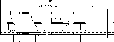
size. In the simulated study, the pipes with an inner diameter of 50 mm, the 4 mm wall thickness, and the 920 mm perforated/slotted length were used. The perforated/slotted ratio varied from 2 %, 3 % to 5 %. The shapes of cavities were Circular Perforated Cavity (CPC), Axial Slotted Cavity (ASC), and Perpendicular Slotted Cavity (PSC). The widths of cavities varied from 1.5 mm, 2 mm to 3 mm. The Reynolds number ranged between 10,000 and 80,000 with the increment of 10,000. There was no flow through the perforations or slots.
Simulation Setup
To calculate the pressure drop along the different perforated/slotted pipes, an academic finite volume code ANSYS Fluent 14.5 was employed. The numerical simulations used the SIMPLE, standard k-ε turbulent model, which was previously used and proved to have good agreement compared to experimental results [9]. The fluid was water, entered the pipes at a temperature of 25o, with a constant density of ρ = 998.2 kg/m3, and the viscosity of μ = 0.001 kg⁄ms. It was also assumed that no-slip boundary condition along the isothermal walls. The inlet Reynolds number ranged from 10,000 to 80,000. The pipes were assumed hydraulically smooth on unperforated or non-
МИСиС
slotted areas. Two initial conditions were considered: the mass flow at the inlet and the pressure at the outlet.
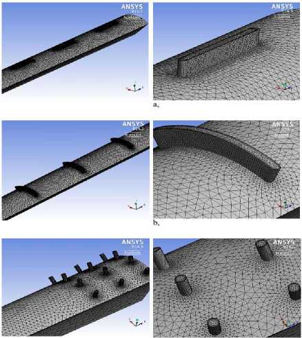
The pipes were uniformly perforated or slotted with different sizes, different shapes (i.e. CPC, ASC, and PSC), and different ratios. These pipes had 2, 3 and 5 percent of open ratio. The widths of cavities varied from 1.5 mm, 2 mm to 3 mm. A total number of 27 pipes were calculated. The configurations of numerical apparatus and computational meshes of flows in pipes are shown in Fig. 1 and Fig. 2, respectively. The flows in pipes were discretized within AN-SYS Meshing environment before solving 520
by the Fluent solver. In the calculating process, symmetries were used to reduce computational time and resource.
Results: Effect of Cavity Shapes on Roughness Friction Factor
Simulated data showed that flows in pipes with different cavity shapes produced different pressure drops. It can be seen in Fig. 3, Fig. 4, Fig. 5, and Fig. 6 that the friction factors tend to have smaller values than that of in regular pipes at small Reynolds number (approx. 15,000 for the ASC and PSC pipes, and 15,000 - 35,000 for CPC pipes).
Q out
cav q cav q cav q cav
a,
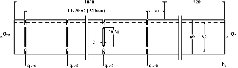
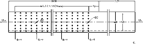
Fig. 1. Configurations of calculation apparatus
Q in
Unperforated Pipes ASC-2%-1.5mm
PSC-2%-1.5mm 0.0400
0.0400
0.0350
0.0300
0.0250
0.0200
0.0150
to
0.0100
0.0050
0.0000
CPC-2%-1.5mm
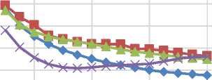
Fig. 2. Computational meshes of flows in pipes: a - ASC pipes; b - PSC pipes; c - CPC pipes
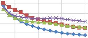
Unperforated Pipes ASC-3%-2mm
PSC-3%-2mm CPC-3%-2mm
0.0350
0.0300
V
0.0250
Й
0.0200
.у
0.0150
0.0100
0.0050
20000 40000 60000 80000
Reynolds Number (Re)
Fig. 3. Friction Factors in pipes with 2 % cavity ratio, 1.5 mm size
0.0000
0 20000 40000 60000 80000
Reynolds Number (Re)
Fig. 4. Friction Factors in pipes with 3 % cavity ratio, 2 mm size
МИСиС
0.0400
£
0.0300
Л to с
0.0200
to
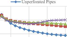
—♦— Unperforated Pipes —■— ASC-5%-2mm
—*— PSC-5%-2mm CPC-5%-2mm
0.0400
0.0350
с
0.0300 о
« 0.0250
0.0100
О 0.0200
I0.0150
0.0100
0.0050
0.0000
0 20000 40000 60000 80000
Reynolds Number (Re)
Fig. 5. Friction Factors in pipes with 5 % cavity ratio, 3 mm size
This effect can be explained due to less contact area between flow and pipe’s wall, while the cavities have not yet had effects on the flow profile. The phenomenon of decreasing friction factor at small Reynolds number happened seemingly to solely the 1.5 mm size CPC pipes, at all cavity ratios (2 %, 3 %, and 5 %).
When the Reynolds number increases, there are different trends between various cavity shapes. The friction factors for ASC and PSC pipes reduced with the increase in Reynolds number. The rate of decrease is slower than in normal pipes. Generally, they are still as 18 % - 36 % larger as in comparison with data in unperforated pipes. In contrast, the friction factors in CPC pipes showed the increase with the increase of Reynolds number from 35,000 to 65,000. Beyond this point, the values of friction factors started to decrease. In general, at the high Reynolds number, the friction factors in CPC pipes are 18 % - 60 % bigger as compared to regular pipes and 0 % - 18 % greater than that of in ASC and PSC pipes. The magnitude of the differences also depends upon the size of cavities. When the cavity size increased, the difference in roughness friction factor become larger.
Conclusions
Numerical results have shown that when velocity in a wellbore is high
0.0000
0 20000 40000 60000 80000
Reynolds Number (Re)
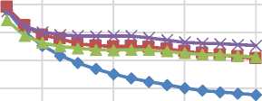
Fig. 6. Friction Factors in pipes with 5 % cavity ratio, 2 mm size
(i.e. Re > 50,000), the flow in CPC pipes introduced the largest roughness friction factors, hence the biggest pressure drops. Meanwhile, the ASC pipes produced slightly less roughness friction factors compared to PSC pipes. This result is fundamental to the investigation of a more complicated situation where inflow through cavities exists.
References Effect of cavities shapes on the roughness friction factor in perforated and slotted horizontal wells used to dewater opencast mines
- Eichler R.A., Drebenstedt C. Innovative Dewatering Concepts for Open Cast Mines Using Horizontal Wells (HDD-Wells), Mine Planning and Equipment Selection, 2014, pp. 697-706.
- Mansel H., Drebenstedt C., Jolas P., Blankenburg R. Dewatering of Opencast Mines using Horizontal Wells, International Mine Water Association, 2012.
- Tran D.H., Drebenstedt C. Challenges during Horizontal Directional Drilling (HDD) Wells Installation for Dewatering Opencast Mines, Scientific Reports on Resource Issues, Freiberg, Germany, 2014.
- Tran D.H., Drebenstedt C. Considerable Aspects to Select Filter Wells for Dewatering, Scientific Reports on Resource Issues, Freiberg, Germany, 2015.
- Jiang W., Sarica C., Ozkan E., Kelkar M. Investigation of the Effects of Completion Geometry on Single-Phase Liquid Flow Behavior in Horizontal Wells, Journal of Energy Resources Technology, Bd. Vol. 123, 2001, pp. 119-126.
- Su Z., Gudmundsson J.S. Perforation Inflow reduces Frictional Pressure Loss in Horizontal Wellbores, Journal of Petroleum Science and Engineering, Bd. 19, 1998, pp. 223-232.
- Su Ze, Gudmundsson J.S. Friction Factor of Perforation Roughness in Pipes, Society of Petroleum Engineers, 1993.
- Su Ze, Gudmundsson J.S. Pressure Drop in Perforated Pipes: Experiments and Analysis, Society of Petroleum Engineer, Melbourne, Australia, 1994.
- Abdulwahid M.A., Dakhil S.F., Injeti N.K. Numerical Investigation of the Turbulent Flow Parameters Distribution in a Partly Perforated Horizontal Wellbore, European Scientific Journal, Bd. Vol. 9, 2013, pp. 372-387.
