Effect of Four Wave Mixing on AP-DCDM-WDM Fiber Optic System with Different Power per Channel

Author: Farman Ullah, Aamir Khan, Nadia N Qadri, Muhammad MasoodSarfraz
Journal: International Journal of Information Engineering and Electronic Business(IJIEEB) @ijieeb
Article in issue: 3 vol.5, 2013.
Free access
Absolute polar duty cycle division multiplexing over WDM is a multiplexing technique which promises better spectral efficiency. Non linearities in fiber optic communication are major issues, especially the effect of four wave mixing. This paper presents the effect of four wave mixing on 40 Gbps AP-DCDM over WDM fiber optic systems. The system was tested by simulating the AP-DCDM-WDM design in Optisystem software and MATLAB code. From the results the effect of four wave mixing on the system is presented under different configurations such as input power per channel. Simulation results have shown that AP-DCDM-WDM systems have greater tolerance to dispersion and have better receiver sensitivity than other conventional techniques. The effect of FWM on AP-DCDM-WDM system is also less than on other conventional techniques on basis of simulation.
AP-DCDM, Four Wave Mixing, Channel Spacing, Power per Channel
Short address: https://sciup.org/15013182
IDR: 15013182
Text of the scientific article Effect of Four Wave Mixing on AP-DCDM-WDM Fiber Optic System with Different Power per Channel
Published Online September 2013 in MECS DOI: 10.5815/ijieeb.2013.03.02
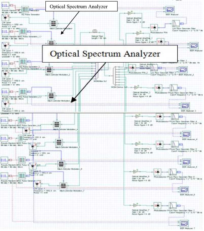
Fig. 5: RZ-WDM 8 Channels System
The design discussed above was then extended for NRZ-WDM system.
After finishing the simulation for RZ-WDM system and NRZ-WDM system, and getting the results for the effect of four wave mixing, the final objective of the paper that is, on AP-DCDM-WDM System was simulated. Here Absolute Polar Duty Cycle Division multiplexing is used with WDM to achieve better performance under the effect of four wave mixing yet at high bit rate [9]. In this setup 4 RZ pulse generators are used with the following configuration from first user to the fourth shown in Table 2.
Table 2: RZ Pulse Generators Configuration
Main | Simulation ]
|
Disp |
Нате |
Value |
Units | |
Mode |
|
Г |
Rectangle shape |
Exponential |
Normal |
|
|
г |
Amplitude |
a.u |
Normal |
|
|
г |
Bias |
au |
Normal |
|
|
Г |
Duty cycle |
025 |
bit |
Normal |
|
г |
Position |
e |
bit |
Normal |
|
г |
Rise time |
oosi |
M |
Normal |
|
г |
Fall time |
0.05 |
bit |
Normal |
|
Disp | Пате |
Value |
Units |
Mode |
|
|
г |
Rectangle shape |
Exponential |
Normal |
|
|
г |
Amplitude |
-1 |
a.». |
Normal |
|
г |
Bias |
0 |
a.u. |
Norma! |
|
г |
Duty cycle |
0.5 |
bit |
Norma! |
|
г |
Position |
fl |
bit |
Normal |
|
г |
Rise time |
0 05 |
bit |
Norma# |
|
г |
Fall time |
005 |
bit |
Norma! |
|
Disp |
llame |
Value |
Units | |
Mode |
|
г |
Rectingle shape |
Exponential |
Normal |
|
|
г |
Amplitude |
1 |
an |
Normal |
|
г |
Bias |
0 |
a.u. |
Normal |
|
г |
Duty cycle |
0 75 |
bit |
Normal |
|
г |
Position |
0 |
bit |
Normal |
|
г |
Rise time |
005 |
bit |
Normal |
|
г |
Fall time |
0 05 |
M |
Normal |
|
Disp |
llame |
Value |
Units \ |
Mode |
|
г |
Rectangle shape |
Exponential |
Normal |
|
|
Г |
Amplitude |
a.u. |
Normal |
|
|
г |
Bias |
0 |
an |
Norma! |
|
г |
Duty cycle |
7 |
M |
Normal |
|
г |
Position |
0 |
M |
Normal |
|
г |
Rise time |
0.05 |
bit |
Normal |
|
г |
Fall time |
005 |
bit |
Normal |
The four RZ Pulse generators with the above mentioned configuration are first combined by an electric adder and passed through an electric absolute circuit to remove the bi polar nature of the signals and then the signal goes into fork which on its output feds one signal to the AM modulate so that the signal is modulated with one external CW laser using AM modulator and the other is fed into matlab component [10][11]. The modulated signal is then fed to one channel of WDM multiplexer and this setup is repeated for as many times as required or available number of channels over WDM. The simulation setup for second channel of WDM 4 X 1 multiplexer is shown in Fig 6.
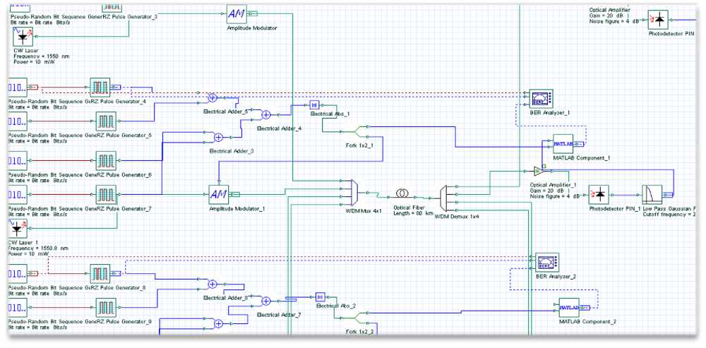
Fig. 6: AP-DCDM-WDM System
For this design, the dispersion value was kept to zero so only the four wave mixing effect is calculated as the BER of the system. The length of the single mode fiber is 80 km. The effective area of the fiber is 64 um^2. The bit rate is 10 Gbps for each user and the bandwidth of WDM multiplexer is 50 GHz. To calculate the BER with zero dispersion, a MATLAB component was used which was attached to a matlab file. Optisystem provides the facility of connecting the layout setup to the matlab files. Matlab file has the appropriate code to do the task and hence the effect of four wave mixing is examined for different power per channel and different channel spacing [12].
-
IV. Results and Discussion
-
4.1 Effect of Four Wave Mixing on AP-DCDM-
-
- WDM Optic Fiber System
As it was discussed in previous section that AP-DCDM-WDM the second channel of WDM was examined without guard bands and four users over that channel are studied. In this section the effect of four wave mixing in the AP-DCDM-WDM environment over this second channel of 4 X 1 WDM multiplexer is examined for four users. The length of the fiber is 80 km and the effective area of the fiber is 64 um^2. The dispersion is kept zero so while in calculation of BER the effect of four wave mixing is mainly calculated. The sequence length is 1 Mb and the bit rate for each channel of WDM is 40 Gbps while 10 Gbps is the bit rate of each user in the AP-DCDM system. The bandwidth of Multiplexer and Demultiplexer is 50 GHz and Channel spacing are 0.4 nm and 0.8 nm. Initially the AP-DCDM was designed and simulated. The eye diagram of this system is shown in Fig.7 and Fig. 8 shows the eye diagram of the AP-DCDM system with guard band.
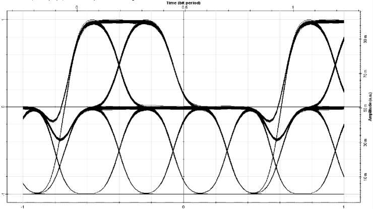
Fig.7: Eye Diagram of AP-DCDM System without Guard Band
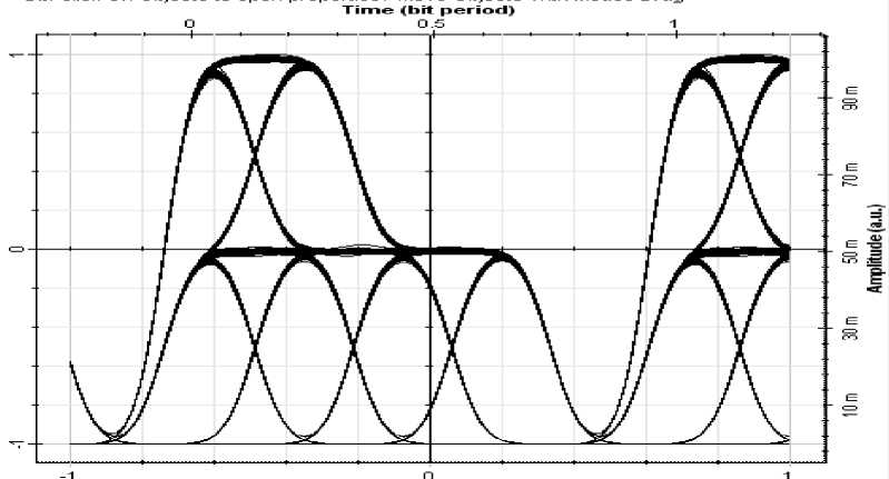
Fig.8: Eye Diagram of AP-DCDM System with Guard Band
The AP-DCDM-WDM system without guard band is the focus of this paper and simulation under various conditions was performed on this system and the results discussed in this section are related to the AP-DCDM-WDM system without guard band.
-
4.2 Effect of Power per Channel with 0.4 nm Channel Spacing
The AP-DCDM-WDM system was first simulated with 0.4 nm channel spacing between the channels of WDM. The system was first tested with input power per channel of 1 mW. For which the Fig9 shows the eye diagram.
Time (bit period)
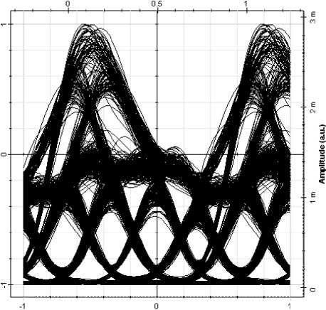
Fig.9: Eye Diagram for input Power per Channel of 1 mW
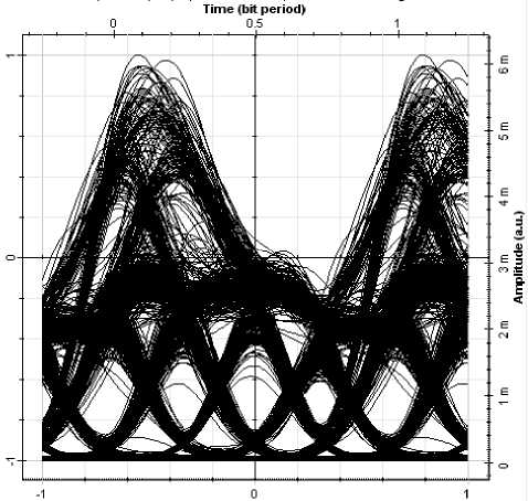
Fig. 10: Eye Diagram for input Power per Channel of 2 mW
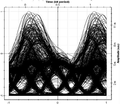
Fig. 11: Eye Diagram for input Power per channel of 4 mW
Then the system was tested for input power of 2 mW, 4 mW and 6 mW. The results in of these changes to input power per channel are shown in Fig. 10 Fig. 11 and Fig. 12 in the form of eye diagrams respectively. Observing the eye diagrams for each change in input power per channel, it can be stated that as the input power per channel increases the effect of four wave mixing on the system increases.
Time (bit period)
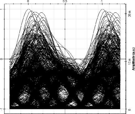
Fig. 12: Eye Diagram for input Power per Channel of 6 mW
-
4.3 Effect of Power per Channel with 0.8 nm Channel Spacing
When the input power per channel was increased the effect of FWM was seen. The system was tested for input power per channel of 2 mW. Fig 12 shows the eye diagram for the system at input power per channel of 2 mW. It is distorted, which indicates that the effect of four wave mixing is encountered by the system and causing the BER to get worst.
Time (bit period)
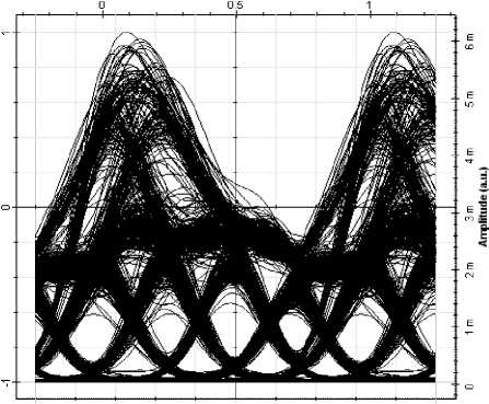
Fig. 13: Eye Diagram at input Power per Channel of 2 mW
The input power per channel was then increased to 4 mW and simulated the design. From the eye diagram shown in Fig. 13, the effect of four wave mixing on the system is obvious as the eye diagram is distorted more and the effect gets severed when the input power per channel is increased to 6 mW and 8 mW subsequently, for which the eye diagrams are shown in Fig 14 and 15 respectively.
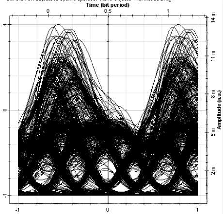
Fig.14: Eye Diagram at input Power per channel of 4 mW
Time (bit period)
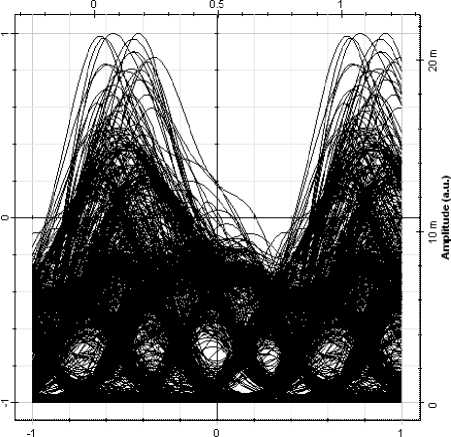
Fig.15: Eye Diagram at input Power per Channel of 6 mW
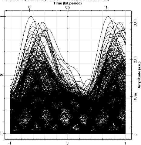
Fig.16: Eye Diagram at input Power per Channel of 8 mW
For the above discussed values of the input power per channel the overall system response is depicted in Fig. 17.
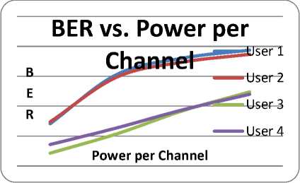
Fig. 17: BER vs. Power per Channel
Obtaining the results as shown in the above figure and observing the eye diagrams for different input power per channel the fact is quite obvious to state that as the input power per channel increases the effect of four wave mixing on the system increases. To transmit the signal over long distance input power is needed but the fact just observed is that by increasing the power the effect of four wave mixing on system increases and transmitted information may be lost due to corrupted data. Though, there is clear restriction on input power per channel, but techniques such as unequal channel spacing and in presence of dispersion the effect of four wave mixing even when the input power is increased can be reduced.
-
V. Conclusion and Recommendation
In this paper, 40 Gbps AP-DCDM over 4 channels WDM system was analyzed for performance under the effect of four wave mixing which is the main non linearity in optical fiber communication system.
It is obvious from results that as the input power per channel are increased, the effect of four wave mixing also increased. For longer distance, the input power per channel is required for signal strength. For this purpose the unequal channel spacing technique could be used to reduce the effect of four wave mixing.
Moreover, results indicated that when the channel spacing is increased, the effect of four wave mixing is noticed to be decreased. With narrow channel spacing the effect of four wave mixing is more severe and signal gets distorted.
Furthermore, it is evident from results when the number of channels increases, the effect of four wave mixing increases.
Comparing the results of AP-DCDM-WDM system, with RZ-WDM and NRZ-WDM system, it would clearly indicate that AP-DCDM-WDM has more spectral efficiency and is less prone to effect of four wave mixing, while on the other hand NRZ-WDM system is better in performance than RZ-WDM system where the criteria of performance is, receiver sensitivity, effect of dispersion and effect of four wave mixing.
The AP-DCDM-WDM fiber optic system elaborated in this paperand the effect of four wave mixing on it was done when the AP-DCDM system was used without guard band. So, it is recommended to study the effect of four wave mixing on the AP-DCDM-WDM fiber optic system with guard band.
Also in quest of making the spectral efficiency better, techniques for reducing the effect of four wave mixing can be proposed such as in the presence of dispersion, the effect of power per channel can be tested.
References Effect of Four Wave Mixing on AP-DCDM-WDM Fiber Optic System with Different Power per Channel
- G.E.Kaiser, Optical Fiber Communications, 3rd edition, McGraw Hill, New York.
- Harry J. R. Dutton, Understanding Optical Communication, IBM Corporation, 1998.
- RazaliNgah, Optical Time Division Multiplexing For Optical Communication System, University Technology Malaysia, 2008.
- Amin Malekmohammadi, Ahmad FauziAbas, MohamadKhazani Abdullah, GhafourAmouzadMahdiraji, MakhfudzahMokhtar, MohdFadlee A. Rasid, Absolute Polar Duty Cycle Division Multiplexing over wavelength division multiplexing system, 2009.
- Amin Malekmohammadi, Ahmad FauziAbas, MohamadKhazani Abdullah, GhafourAmouzadMahdiraji, MakhfudzahMokhtar, MohdFadlee A. Rasid, Realization of high capacity transmission in fiber optic communication systems using AP-DCDM technique, 2009.
- Malekmohammadi, Amin (2009) Absolute Polar Duty Cycle Division Multiplexing for High-Speed Fiber Optic Communication System. PhD paper, Universiti Putra Malaysia.
- Govind P. Agrawal, Non Linear Fiber Optics, third edition, Academic Press, 2001.
- M.T. Al-Qdah, H.A. Abdul-Rashid, K. Dimyati, B.M. Ali and M. Khazani, Effect of optical beat interference in SCM/WDM optical networks in presence of FWM, KMITL Sci. Tech. J. Vol. 5 No. 3 Jul.-Dec. 2005.
- S. P. Singh and N.Singh, Non linear effects in optical fibres: Origin, Management and Applications, Progress In Electromagnetics Research, PIER 73, 249-275, 2007.
- Tan Saw Chin, F.M. Abbou and Ewe Hong Tat, Impact of Four Wave Mixing (FWM) in Routing and Wavelength Assignment, American Journal of Applied Sciences 5 (8): 1059-1063, 2008.
- Malekmohammadi, Amin (2009) Absolute Polar Duty Cycle Division Multiplexing for High-Speed Fiber Optic Communication System. PhD paper, Universiti Putra Malaysia.
- Ezra Ip and Joseph M.Kahn, Fellow, IEEE Power Spectra of Return-to-Zero Optical Signals JOURNAL OF LIGHTWAVE TECHNOLOGY, VOL.24, NO.3, MARCH 2006.
