Effect of Friction on Ball-On-Sphere System Modelled by Bond Graph

Author: Abdulmumin M. Yesufu., Aliyu D. Usman
Journal: International Journal of Modern Education and Computer Science (IJMECS) @ijmecs
Article in issue: 7 vol.9, 2017.
Free access
This paper presents the model analysis of ball-on-sphere system by considering the effect of friction. The ball-on-sphere system is modelled using bond graph technique. In the bond graph modelling procedures of the system, the various subsystems, storage elements, junction structures, transformer elements, dissipating element with appropriate causality assignments and energy exchange that make up the ball-on-sphere system were identified and modelled. In the model analysis of the ball-on-sphere system, the developed model with effect of friction had time of angular position response of the ball (1504237026699027.png) achieved at 0.5253s while in the system model without effect of friction, time of 0.5408s was achieved for the angular position response of the ball (1504237026699027.png). This shows 2.9% improvement of the angular position response of the ball considering frictional effect in the developed bond graph model of the system.
Ball-on-Sphere System, Non-linear System, Bond graph, Friction and Modelling
Short address: https://sciup.org/15014983
IDR: 15014983
Text of the scientific article Effect of Friction on Ball-On-Sphere System Modelled by Bond Graph
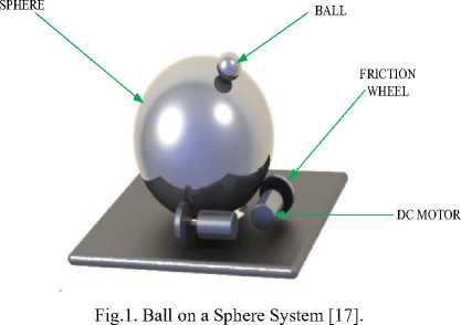
Ball-on-sphere system is a class of multi-input multioutput (MIMO) nonlinear systems which is designed to control and operate a ball on the top of a sphere. The system is nonlinear, unstable and under actuated. As such, it mainly serves as a benchmark for nonlinear control systems [15]. The ball-on-sphere system consists of the following basic components; a sphere, two motors, and two friction wheels [17]. Over the surface of the sphere, a ball is to be stabilized by controlling the rotation of the sphere through two motors. According to the linearized model with respect to the equilibrium point, the system can be decoupled into two independent ball and wheel systems [14] and this is said to be full state feedback linearizable [10].
The ball-on-sphere is an important class of balancing systems with applications from robotics to transportation and aero-space in the following areas: in modelling and stabilization of nonlinear control systems such as spaceships, humanoid robot and intercontinental missile guidance system.
The ball-on-sphere system is as shown in Fig. 1.
The dynamics of the ball-on-sphere system are nonlinear and complex and its parameters are interdependent in various directions; they have been considered to be two independent ball and wheel systems around the equilibrium point [6] Parameter identification is among the most difficult steps in model design phase, which is the most cause of model errors [1]. The dynamics of ball-on-sphere system have been modeled using Euler-Lagrange modeling techniques. However, the existing method is limited with respect to not having detailed knowledge of the system’s parameters [17]. The dynamic equations of the ball-on-sphere system are nonlinear and coupled. Hence, it is normally difficult to obtain significant dynamics of the system using the various conventional numerical analytical tools.
-
II. Related Works
This section presents a brief review of previous works carried out to model the ball-on-sphere system and other related systems.
-
[10] Model the ball-on-sphere system using Euler-Lagrange modelling technique. The Euler-Lagrange technique was used to obtain the translational and rotational dynamics for the nonlinear system model. In the work, feedback linearization was used to transform the nonlinear model of the system to linear model for the system analysis. However, the developed model did not
take into consideration the resolution of all the forces acting on the ball such as the frictional force.
[12] Worked on the model of ball-on-sphere system for the purpose of designing a nonlinear adaptive feedback linearization for stability analysis of the nonlinear system. Adaptive feedback linearization was used to update the system’s parameters by a suitable update law for stability analysis for the system. However, one of the most difficult steps in the model design phase was the parameter identification, which was the main cause of modelling errors. As such, the technique was inadequate to give thorough analysis of the system parameters.
[14] Modelled the dynamics of the ball-on-sphere system using Lagrange approach. The dynamics of the system presented were coupled and nonlinear. Hence, the system was simplified based on two decoupled ball-and-wheel system. To simplify the developed nonlinear model of the system, the predominant nonlinear terms of the ball and wheel system were retained, but the high order coupling terms were neglected. The simplified model was used for controller design for the purpose of stability analysis of each decoupled system. However, the developed model did not take into consideration the resolution of all the forces acting on the system such as the frictional force.
[9] worked on the modelling of ball and plate system for stability analysis of the system. In the work, exact non-linear differential equations of the ball and plate system were first derived by the use of Lagrange-Euler equations. The nonlinear equations of the model were then transformed to linear model for the purpose of dynamic behaviour analysis of the system. The motor model was also presented in the work to show the effect of external torque on the ball-on-plate system. However, considering the assumptions made in the modelling process, not all forces acting on the system were considered.
[8] carried out bond graph detailed modelling and the design of feedback linearizing technique applied to an inverted pendulum system. In the modelling of the system using bond graph technique, the following steps were adopted: the first step was to write a word bond graph which contains words instead of standard symbols for the main components, and bonds for power and signal exchange of the system. The next step was to replace words by standards elements which contain precise mathematical or functional relations. The system was decomposed into three subsystems that were modeled separately: dc motor, gear and inverted pendulum. 20sim modelling environment was used to create and validated the developed model. The mathematical equations derived were used to formulate the state space equations starting from the constitutive relations of elements for the system analysis. However, in the work, bond graph based structural analyses of the developed model were not considered in order to study the underlying dynamic behaviour of the system.
-
III. Ball-on-Sphere System Dynamics
Nonlinear control systems are those control systems where nonlinearity plays a significant role, either in the controlled process (plant) or in the controller itself [7]. Most physical systems are inherently non-linear. A common engineering practice in analyzing a non-linear system is to linearize it about a nominal operating point and analyze the resulting linear model [2]. The ball-on-sphere model is non-linear and for ease of control and analysis it is expected to be linearized about an operating point. The operating point, at the instance of linearization, is that point at which all state and input variables are initialized to zero [2].
-
[10 ] developed a mathematical model of the ball-on-sphere system using the Euler Lagrange formulation by considering the following assumptions:
-
1) The ball rolls on the sphere without slipping.
-
2) The ball is always in contact with the sphere and
-
3) All frictional force is neglected
The basic feature of the ball-on-sphere system is shown in Fig. 2:
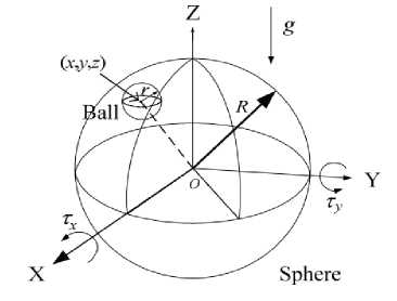
Fig.2. Ball-on-Sphere System [10].
The parameters of the system as shown in Fig. 2 are described as follows:
R is the Radius of the sphere; r is the radius of the ball; τ x is the torque exerted in the x-axis direction; τ y is the torque exerted in the y-axis direction ; g is the gravitational force and (x, y, z) is the position of the ball.
The obtained mathematical model using Euler-Lagrange model of the decoupled dynamics of the ballon-sphere system are as shown as presented by [10]:
( R + r ) m + I b
( R + r )
••
6 x -
I bR 2 r
••
в — mg sin 6 = 0
- I b
R ( R + r )
•• R2 ••
6 x + \Ib + Ib— I в = T y ( 2)
r 2
-
-
IV. Bond Graph Modelling Technique
Bond graph is a multi-domains modelling technique that simultaneously conveys the topological structure and the computational structure of the system being modelled [4].
Bond graph method is based on energy and information flow in systems. Some applications and fundamentals of bond graph are found in [4] and [13]. In [5], it was established that bond graph technique is a tool that can be used to model systems with different energy domain characteristics. Similarly, for concurrent modelling of mechatronic systems, [4] demonstrated the usefulness of bond graph as a multi-domain modelling technique is less prone to errors and is a simple modelling approach that takes into account multi-energy exchange in systems.
Bond graph has a vertex and an edge; the vertices represent sub-models A and B while the edge stands for the energy connection between power ports. [4]. This is as shown in Fig. 3:
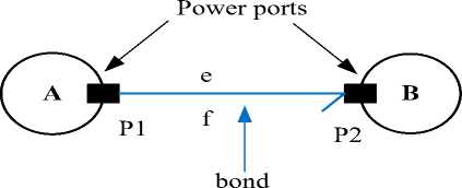
Fig.3. Bond Graph Schematic Diagram [4]
Bond graph is a unique technique for multi-domain systems modelling as it provides a systematic method for representing the interconnection of multi-energetic system elements. It provides room for expansion, incorporation of new sub-models in an existing one, efficient structural analysis, fault detection and isolation (FDI) capabilities. Bond graph is easily incorporated and compatible with most simulation software’s, like 20-sim, Simulink/Matlab, Dymola and labVIEW [11].
The advantages of bond graph modelling over other modelling techniques such as variational and network techniques are as follows [3]:
-
1) It is a unique language for all physical domains.
-
2) Its models are easier to understand in terms of the physical relation between components.
-
3) It clearly shows the cause and effect relations in the model.
-
4) It allows further possible development and
evolution of the model.
-
5) It is also a tool for analyzing the system’s
structural properties.
-
6) It conveys the transfer of energy, power and information between subsystems.
-
7) It has computer aided modelling support.
-
A. Bond graph modeling implementation
The bond graph procedures of modelling systems include the following steps [16]:
-
1) Identification of the various subsystems, storage elements (e.g. moment of inertia parameters), the dissipating elements (e.g. frictional parameter) modelled as loss of free energy and sources of energy (e.g. torque) of the system being modelled.
-
2) Identification of the various junction structures which are the energy distribution in the system i.e. the 1-junctions and 0-junctions.
-
3) Insertion of 1-junctions to the identified distinct angular velocities of the system.
-
4) Identification of the reversible transformation of energy (TF) element i.e. separately relating the efforts at the ports and the flows at the ports of the system.
-
5) Attachment of a reference direction for the energy flow to each bond (half arrow).
-
6) Mapping out and connecting the causal bonds of the system components with appropriate causality assignment.
-
7) Simplification of the bond graph structure by removing all 1-junctions representing an angular velocity identical to 0-junction along with all incident bonds.
-
B. Causality Concept
In bond graph theory, the concept of causality is important. This refers to cause (input) and effect (output) relationship. Thus, in the process of bond graph modelling, causality assignment plays an important role, which is implicitly introduced and it is graphically represented by a short stroke, called causal stroke, placed perpendicular to the bond at one of its ends indicating the direction of the effort variable. Causal stroke assignment is independent of the power flow direction. The concept leads to generation of state space equations from the bond graph structure.
The decision to make which of the component models to reflect the causality is systematic and energy directed. Fig. 3.1a to 3.3b shows the possibilities of causality assignment for the given elements. For storage elements such as Inertance (I) and Capacitance (C), integral causality is preferred.
The design of causality for a capacitance component is as shown in Fig. 3.1a and Figure 3.1b. Fig. 3.1a structure shows integral causality configuration while Fig. 3.1b shows differential causality configuration.
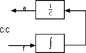
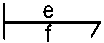
Fig.3. 1a: Capacitance (C) Causality Integral Configuration [4].
e f
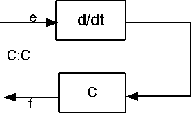
Fig.3.1b: Capacitance (C) Differential Configuration [4].
-
V . Materials And Methods
This section describes the procedures used for the modelling and analysis of the ball-on-sphere system.
-
A. Modelling of Ball-on-Sphere System
In the modelling procedures, the following steps explained the methodology adopted:
For the design of causality of an inertance component, Fig. 3.2a and Fig. 3.2b show the two variants. Fig. 3.2a shows integral causality configuration while Fig. 3.2b shows the differential causality configuration.
i. The ball-on-sphere system was first decoupled into two subsystems; ball and wheel systems in x-axis as shown in Fig. 4:
e f
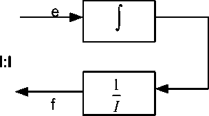
Fig.3.2a: Inertance (I) Causality Integral Configuration [4].
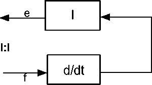
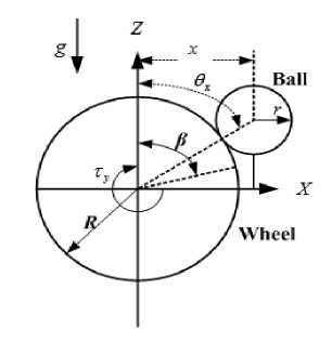
Fig.4. Ball and Wheel System in x-axis [14].
Fig.3.2b: Inertance (I) Causality Differential Configuration [4].
For the design of causality of resistance component of a system, Fig 3.3a and Fig 3.3b show the two variants. Fig. 3.3a shows integral causality while Fig. 3.3b shows differential causality configuration of the resistance variant.
e-► 1
r
ef н R:rf
ii. Furthermore, the various physical components of the system were identified and modelled. These include the source of energy i.e. dc motor, storage elements i.e. moment of inertias of the ball and wheel, the dissipating element i.e. frictional force.
iii. The junction structure of the system i.e. 0, 1, and transformers (TF) ratios i.e.( T ,T and T ) ports were inset via a 0-junction between two 1-junctions.
direction to connect the identified physical component of the system and appropriate causality were applied in order to specify the transfer of energy within the system.
B. Stability Analysis of Ball-on-Sphere System
The procedures used for stability analysis of the ballon-sphere system involve the following steps:
Fig.3.3a: Resistance (R) Integral Configuration [4].
R:r
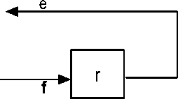
Fig.3.3b: Resistance (R) Differential Configuration [4].
-
i. The developed casual bond graph of the system was used to generate the nonlinear mathematical equations of the system.
-
ii. Linearization of the nonlinear equations about an operating point was carried out in order to generate state space matrices.
-
iii. The generated state space matrices were used to simulate and analyse the developed model parameters using Matlab 2015a.
-
VI. Results and Discussion
This section presents and discusses the results of the developed bond graph model, the causal bond graph, the derived mathematical model and stability analysis of the developed model with and without effect of friction.
-
A. Bond Graph Model of Ball-on-Sphere System
The developed bond graph model of the ball-on-sphere system is as shown in Fig. 5. The bond graph graphical representation of the system shows the dynamics of the rotation and revolution of the ball as the sphere rotates due to the applied torque. The developed bond graph model is without causal assignment. This means there is no causal and effect relationship specified in the model and as such, no further analysis can be carried out on the developed model such as deriving the mathematical model of the ball-on-sphere system and amongst other analyses provided causalities are assigned.
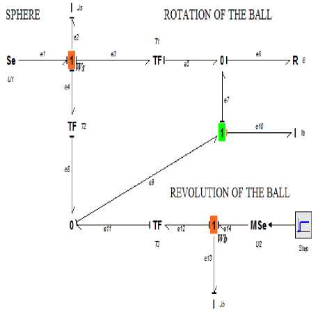
Fig.6. Causal Bond Graph of Ball-on-Sphere System
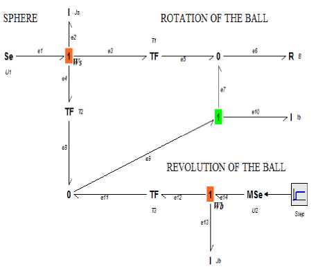
Fig.5. Bond Graph Model of Ball-on-Sphere System
C. Mathematical Model of Ball-on-Sphere System
The results of the mathematical equations obtained from the developed causal bond graph model are presented in this subsection. The mathematical model describes the dynamics of the ball-on-sphere system with respect to the integrals of the storage elements which are the state variables of the system. All the integral storage elements i.e. moment of inertia of the ball and sphere i.e. ( I and I ) correspond to stored state variables (P i.e. momentum). The equations were derived for their time derivatives (i.e. effort and flow) based on bond graph equations algorithmic procedures.
The dynamic equations for the decoupled ball-on-sphere system in the x-axis are as shown:
B. Causal Model of Ball-on-Sphere System
Causality was assigned to the developed bond graph model of the ball-on-sphere system based on the sequential causality assignment procedures (SCAP). The developed causal bond graph model shows the cause and effect relationship in the system and also specifies the transfer of energy within the system. Furthermore, the mathematical model of the ball-on-sphere system was derived from the developed causal bond graph model. The result of the developed causal bond graph model is as shown in Fig. 6:
, A ( R + r) "
( R + r ) m + I 9 , +
r
R ( R + r )
r
I b
••
9 +
x
R
Ib 2
r
•• в -
( R + r ) •
—^ B O - mg sin 9 = 0 r
R 2 •• (R + r)
I ; +— 1„ в - 2 R^—^BO , = т
S 2b 2 xy rr
Where т is the torque exerted in y-axis direction, Is is the moment of inertia of the sphere, R is the radius of the sphere, r is the radius of the ball and b is the frictional parameter.
The generated mathematical equations were used in the model analysis of the ball on sphere system.
D. Ball-on-Sphere Model Stability Analysis
The developed ball-on-sphere system model was simulated and analyze using Matlab 2015a environment. The results of the simulated parameters are as shown in Fig. 7. The time of angular position response of the ball ( β ) achieved with the model with friction was 0.5253s. While in the model without friction consideration, time of 0.5408s for the angular position response of the ball ( β ) was achieved. The results show 2.9% improvement on the angular position response of the ball in the developed bond graph model with frictional effect.
Angular Position of the Ball in X-direction
0.06
0.05 т Е с 0.04
О
и
2 0.03 т
X
^^^^™ Model with friction
"•■' Model without friction
0.02 с о
0.01 о Q.

-0.01 гу.....
-0.02 t-----------[-----------[-----------[-----------[-----------[-----------[-----------2-----------С-----------Е-----------[
0 1 2 3 4 5 6 7 8 9 10
Time(s)
Fig.7. Ball-on-Sphere System Model Analysis
Table 1 shows comparison of the characteristics of transient response of the ball-on-sphere system model with friction and without frictional effect.
Table 1. Comparison of Ball-on-Sphere System Model Results With and Without Friction
|
The System Response |
Model With Friction |
Model Without Friction |
|
Rise Time |
0.1743 |
0.1835 |
|
Settling Time |
0.5253 |
0.5408 |
|
Settling Min |
-0.0022 |
-0.0015 |
|
Settling Max |
0.0070 |
0.0050 |
|
Overshoot |
6.2690e+07 |
6.3737e+07 |
|
Undershoot |
1.9450e+06 |
1.9318e+06 |
|
Peak |
0.0701 |
0.0500 |
|
Peak Time |
0.0026 |
0.0018 |
From table 1, it can be depicted that the model with friction has the lowest settling time compared to the model without friction as regards the time of angular position response of the ball.
-
VII. Conclusion
In this work, the model analysis of ball-on-sphere system model with and without the effect of friction is being presented. From the model analysis, the developed model with friction had an angular position response of the ball at 0.5253s while the model without the effect of friction had angular position response of the ball at 0.5408s. The results show 2.9% improvement on the angular position response of the ball in the developed bond graph model with effect of friction. The bond graph technique is an efficient and simplified approach of modelling the ball-on-sphere system. The developed causal bond graph model of the ball-on-sphere system can be directly used to carry out structural properties information analysis using bond graph in order to evaluate the dynamic behavior of the system.
-
[1] Dauphin-Tanguy, G., Rahmani, A. & Sueur, C. (1999). Bond graph aided design of controlled systems. Simulation Practice and Theory, 7 (5), 493-513.
-
[2] Hassan. (2003). Nonlinear Systems Third Edition,Prentice Hall, 750, ISBN 0-13-067389-7. 47 (4), 208.
-
[3] Yu, B.& Van Paassen, A. (2004). Simulink and bond graph modeling of an air-conditioned room. Simulation Modelling Practice and Theory, 12 (1), 61-76.
-
[4] Borutzky, W., Orsoni, A., & Zobel, R. (2006). Bond graph modelling and simulation of mechatronic systems an introduction into the methodology. Paper presented at the 20th European conference on modeling and simulation.
-
[5] Kayani, S. A. & Malik, M. A. (2008). Bond-graphs+ genetic programming: Analysis of an automatically synthesized rotary mechanical system . In Proceedings of the 10th Annual Conference Companion on Genetic and Evolutionary Computation . (pp. 2165-2168).
-
[6] Ho, M.-T., Tu, Y.-W., & Lin, H.-S. (2009). Controlling a ball and wheel system using full-state-feedback linearization [Focus on Education]. Control Systems, IEEE, 29 (5), 93-101.
-
[7] Binder, E. M., Hirokawa, N.& Windhorst, U. (2009). Nonlinear Control Systems. Encyclopedia of Neuroscience , 1-9.
-
[8] Bobaşu, E., Roman, M. & Şendrescu, D. (2010). Bond Graph Modelling and Nonlinear Control of an Inverted Pendulum. In Process Control 2010 (1), 1-5.
-
[9] Mohammad, N.& Khashabi, D. (2011). Modelling and Control of Ball and Plate System. Amirkabir University of Technology , 1-22.
-
[10] Liu, S.-Y., Rizal, Y., & Ho, M.-T. (2011). Stabilization of a ball and sphere system using feedback linearization and sliding mode control. Paper presented at the Control Conference (ASCC), 2011 8th Asian.
-
[11] Ngwompo, R. F. (2011). Bond graph-based filtered inversion of multivariable physical systems. Proceedings of the Institution of Mechanical Engineers, Part I: Journal of Systems and Control Engineering , 226 (1), 125-140.
-
[12] Zakeri, E., Ghahramani, A., Moezi, S. A. & Yousef Bazargan-Lari. (2012). Adaptive Feedback Linearization Control Of a Ball on Sphere System. International Conference on Mechanical Engineering and Advanced Technology .
-
[13] Karnopp, D. C., Margolis, D. L. & Rosenberg, R. C. (2012). Multiport Systems and Bond Graphs. System Dynamics: Modelling, Simulation, and Control of
Mechatronic Systems, Fifth Edition , 17-36.
-
[14] Ho, M.-T., Rizal, Y.& Cheng, W.-S. (2013). Stabilization of a vision-based ball-on-sphere system . IEEE International Conference on Control Applications (CCA) , 2013. (pp. 929-934).
-
[15] Alireza, M. S., Ehsan, Z., Yousef, B.-L.& Mohammad, T. (2014). Control of a ball on sphere system with adaptive neural network method for regulation purpose. Journal of Applied Sciences, 14 (17), 2014.
-
[16] Benmoussa, S., Bouamama, B. O.& Merzouki, R. (2014). Bond graph approach for plant fault detection and isolation: Application to intelligent autonomous vehicle. IEEE Transactions on Automation Science and Engineering, 11 (2), 585-593.
-
[17] Moezi, S. A., Zakeri, E.& Bazargan-Lari, Y. (2014). Control of a ball on sphere system with adaptive neural network method for regulation purpose. Journal of Applied Sciences, 14 (17), 2014.
References Effect of Friction on Ball-On-Sphere System Modelled by Bond Graph
- Dauphin-Tanguy, G., Rahmani, A. & Sueur, C. (1999). Bond graph aided design of controlled systems. Simulation Practice and Theory, 7(5), 493-513.
- Hassan. (2003). Nonlinear Systems Third Edition,Prentice Hall, 750, ISBN 0-13-067389-7. 47(4), 208.
- Yu, B.& Van Paassen, A. (2004). Simulink and bond graph modeling of an air-conditioned room. Simulation Modelling Practice and Theory, 12(1), 61-76.
- Borutzky, W., Orsoni, A., & Zobel, R. (2006). Bond graph modelling and simulation of mechatronic systems an introduction into the methodology. Paper presented at the 20th European conference on modeling and simulation.
- Kayani, S. A. & Malik, M. A. (2008). Bond-graphs+ genetic programming: Analysis of an automatically synthesized rotary mechanical system. In Proceedings of the 10th Annual Conference Companion on Genetic and Evolutionary Computation. (pp. 2165-2168).
- Ho, M.-T., Tu, Y.-W., & Lin, H.-S. (2009). Controlling a ball and wheel system using full-state-feedback linearization [Focus on Education]. Control Systems, IEEE, 29(5), 93-101.
- Binder, E. M., Hirokawa, N.& Windhorst, U. (2009). Nonlinear Control Systems. Encyclopedia of Neuroscience, 1-9.
- Bobaşu, E., Roman, M. & Şendrescu, D. (2010). Bond Graph Modelling and Nonlinear Control of an Inverted Pendulum. In Process Control 2010 (1), 1-5.
- Mohammad, N.& Khashabi, D. (2011). Modelling and Control of Ball and Plate System. Amirkabir University of Technology, 1-22.
- Liu, S.-Y., Rizal, Y., & Ho, M.-T. (2011). Stabilization of a ball and sphere system using feedback linearization and sliding mode control. Paper presented at the Control Conference (ASCC), 2011 8th Asian.
- Ngwompo, R. F. (2011). Bond graph-based filtered inversion of multivariable physical systems. Proceedings of the Institution of Mechanical Engineers, Part I: Journal of Systems and Control Engineering, 226(1), 125-140.
- Zakeri, E., Ghahramani, A., Moezi, S. A. & Yousef Bazargan-Lari. (2012). Adaptive Feedback Linearization Control Of a Ball on Sphere System. International Conference on Mechanical Engineering and Advanced Technology.
- Karnopp, D. C., Margolis, D. L. & Rosenberg, R. C. (2012). Multiport Systems and Bond Graphs. System Dynamics: Modelling, Simulation, and Control of Mechatronic Systems, Fifth Edition, 17-36.
- Ho, M.-T., Rizal, Y.& Cheng, W.-S. (2013). Stabilization of a vision-based ball-on-sphere system. IEEE International Conference on Control Applications (CCA), 2013. (pp. 929-934).
- Alireza, M. S., Ehsan, Z., Yousef, B.-L.& Mohammad, T. (2014). Control of a ball on sphere system with adaptive neural network method for regulation purpose. Journal of Applied Sciences, 14(17), 2014.
- Benmoussa, S., Bouamama, B. O.& Merzouki, R. (2014). Bond graph approach for plant fault detection and isolation: Application to intelligent autonomous vehicle. IEEE Transactions on Automation Science and Engineering, 11(2), 585-593.
- Moezi, S. A., Zakeri, E.& Bazargan-Lari, Y. (2014). Control of a ball on sphere system with adaptive neural network method for regulation purpose. Journal of Applied Sciences, 14(17), 2014.
