Effects of different boundary condition formulations on internal acoustic pressure and vibration loading of an aircraft compartment

Author: Popov P.A., Malykhina O.I.
Journal: Siberian Aerospace Journal @vestnik-sibsau-en
Section: Aviation and spacecraft engineering
Article in issue: 1 vol.27, 2026.
Free access
During the assessment of rocket components vibroacoustic loading using the finite element modeling, it is not feasible to analyze the entire rocket due to the design's complexity and its large spatial scales compared to high-frequency wavelengths. Therefore, in practice, individual structural groups (compartments, rocket fuel tanks, and the warhead) must be considered. This limited model for calculations under rigid constraint can produce distorted vibroacoustic parameter characteristics; these errors will be greater the shorter the considered compartment. To address this issue, it is proposed to use beam finite elements for modeling the missing components of the rocket. This should allow to consider the missing vibration modes propagating along its entire body and affecting the compartment under consideration, as well as the dynamics of its end frames. In this regard, in the proposed article, a finite element model of the stiffened shell of a launch vehicle's dry compartment was developed. The model is constructed from flat and solid finite elements, with brackets containing instruments positioned within it. These brackets represent concentrated masses with specified centering and inertial characteristics. Such structural elements, described by a system of oscillator equations, interact with acoustic (fluid) elements in the model, where the acoustic wave equations are solved. The missing parts of the launch vehicle were modeled using beam elements, considering the existing design of tunnel pipelines, fuel tanks, propulsion systems, etc. The rocket's beam structure is connected to the compartment frames by elastic contact elements. Solving the resulting systems of equations allowed us to determine the displacements of the structural finite elements and pressure pulsations in the acoustic domain. The calculations are presented under various boundary conditions, which take into account low-frequency vibrations that occur during engine operation and their influence on the internal acoustic pressure and the dynamics of the structure, with the beam part of the model and without it.
Rocket compartments, boundary conditions, vibroacoustic model, beam model, internal acoustic pressure, vibration accelerations
Short address: https://sciup.org/148333276
IDR: 148333276 | UDC: 621 | DOI: 10.31772/2712-8970-2026-27-1-158-171
Text of the scientific article Effects of different boundary condition formulations on internal acoustic pressure and vibration loading of an aircraft compartment
Vibroacoustic loading on the structure of aircraft compartments and instruments can lead to fatigue failure of the former and disruption of the stable operation of the latter. In this regard, the testing of vibration strength and stability of launch vehicle components (LV components) is regulated by a number of industry and state standards, and conducting research on this topic allows for the most reliable determination of test modes for equipment and structures, which are later refined during flight operation [1; 2].
An analysis of scientific works related to finding methods for establishing the relationship between external and internal acoustic pressure parameters and vibration acceleration parameters shows that the authors mainly assessed these characteristics either by mathematical modeling methods [3–8], or by experimentally determining these values for structural segments using dual acoustic chambers [9; 10], including the use of intensimetry [11; 12], or by experimental modeling followed by recalculation of results to full-scale structures [9; 13], or during flight development tests [1; 2]. Examples of mathematical modeling include the developed coupled elastic-acoustic model of shell vibration in an acoustic environment, which accounts for the interaction of the shell’s elastic modes with both the external load field and the acoustic modes of the air volume inside the compartment [3; 9]. Currently, due to the widespread use of modern computer modeling tools in engineering and scientific practice, the fi- nite element method (FEM) is gaining increasing popularity due to its versatility [6–8]. The essence of the method lies in reducing the system of equations for structural vibrations and the wave equation to a matrix form describing the interaction between the medium and the structure. Algorithms for solving systems of algebraic equations corresponding to the parameters of a specific problem are currently implemented in software products which, given the current level of computer technology development and the availability of verification methods, offer extensive possibilities for conducting various interdisciplinary studies, including vibroacoustic analysis.
Finite element model of the acoustic domain
To assess the propagation of acoustic waves within the air continuum, the FEM was used. For the mathematical construction of the model, consider the generalized wave equation, which relates a set of parameters such as the acoustical velocity, c 0, the density of the medium, ρ0, the dynamic viscosity, μ, the sought acoustic pressure p = p ( r , t ) in space r = ( x , y , z ) and time (t), and, for example, the mass flow rate Q = Q ( r , t ), representing an external disturbance [6]:
1 d 2 p P o c 02 d t2
-V
f 1
—V p LP o
-V
f ^V
L3Po
Г 1
1 d p
Lpo cо 't J J
-
V( 4 V
QQ 1 ’
P o J J d t LP o J
d r d r d Г V = — i + — j +— k .
d x d y d z
The formulas for the finite element analysis were obtained using the Galerkin method, in which the wave equation (1) is multiplied by trial linearly independent functions W i = w i ( r), the sum of which is an approximation to the solution [14]:
p ( t , r) = X Wi ( r) p i ( t ), Q ( t , r) = ^ w i ( r) Q i ( t ).
Let us integrate each term of equation (1) over the domain Ω with boundary G, where acoustic waves propagate, using (2) and first multiplying by the trial functions w i = w i ( r ):
f ' d 2 pwd Q = p i f ^4 d Q = pM i ;
Q p0c0 dt Q p0c0
Г VI — V p l w i d Q = — f ^ pw i dr - — f V p V w i d Q =
Q Lp o J P o J d n P o Q
= ~ I “ pw d r - p K ; i ii
P o J d n
— f ^pw^dr - pi- f Vw VwdQ = i ii
P o J d n P o Q
J V T^V
1 d p
q
L
3 P o
=*4-v 3Po J dn
о c 2 dt Lpocо 't J J
1 d p
wd Q = V i 3Po Jdn
1 d p _P o c 02 d t
wd r - ^MV i 3 P 0 Q
1 d p _P o c 02 d t
V w i d Q =
H£v
q
L
3 P o
_P o c 02 d t
Q 1
Lp o J J
widГ - p ici ;
w i d Q = - 4 ' | V Q 3 P o J d n Lp o j
w i dr +
5) f— I Q I w i d Q = Q ^f w2d Q . Q d t LP o J P o Q
р о q
Г
4[[ Qi f V w V wd Q ; 3 P 2 Q
The normal velocity at the domain boundary can be calculated as follows [6]:
d Vr ( 4 ц 3 1 ^ r_ 4 ц r^r
-
6) a " = - ,•• aV n v p +з? n v Q.
-
° t V 3 p o c о ° t p o J 3 p o
Let’s group the resulting terms 1–6 and represent them in matrix form:
[ M f ] ( p } + [ C f ] { P } + [ K f ] ( P ) + P o [ R t ] { ° r } = { ff} . (3)
The index f corresponds to the initial data relevant to the considered gas (air); [ M f ] is the acoustic medium mass matrix; [ K f ] is the acoustic stiffness matrix; [ С f ] is the acoustic damping matrix;{ f f } is the acoustic load; [ Rt ] is the transposed matrix of the components of the vectors normal to the acoustic medium surface; p0 is the density of the acoustic (air) medium; { p }, { p } , { p } are the sought pressure pulsation vector and its time derivatives; { a Г} is the acceleration vector on the boundary G; in the case of a coupled formulation, this parameter represents the acceleration of the structural motion and is included in its equation of motion. A more detailed representation of the quantities is listed in formula (3):
щ ( {Ж ^ гc . f^{V w , nV w , }
[ Mf] "J ^2 d “’ [Cf] “J,
Q p0c0 Q 3p0
[ K f ] = j l Z w HZ w l d Q ; [ R f ] t = J { v W i }{ n } t { v w } t d T;
Q P0Г
{ f f } = J
Q
{W}{W}{Qi} 4ц, dQ.
-----------+7T{v w } {v w }{ Q i }
Po
Equation (3) describes the generalized motion of the medium over time. However, if the time dependence is assumed to be strictly harmonic p (r, t) = p (r) e -i “t, which is justified in many cases where transient processes are not considered, equation (3) can be rewritten as follows:
( -[ M f ]® 2 +[ C f ] i ®+[ Kf ] ) { p } + P o [ R t ] { аг } = { ff } • (4)
The solution of the presented equations was implemented in a specialized FEM software [6]. The main input data for the acoustic part of the FEM are presented in Table 1.
Main settings and input data for the acoustic part of the FEM
Table 1
|
acoustical velocity |
343 m/s |
|
Density |
1.2 kg/m3 |
|
Element size |
0.07 m |
|
Number of acoustic elements |
45315 |
|
Number of acoustic nodes |
194944 |
|
Type of acoustic FE |
Hexagonal 20-node (FLUID220) |
|
FE shape |
|
|
Sound absorption coefficient on the internal compartment surface |
10% across the entire frequency range [15] |
Finite element model of the structural domain
Obtaining the vibration response in engineering is one of the most common and rather complex tasks. In vibroacoustics, the relationship between the wave equation and the vibration equation is achieved by considering acoustic re-radiation. The generalized structural equation (s) in matrix form, considering acoustic re-radiation [R]{p} , has the form
[ M s ]{ u } + [ C s ]{ u } + [ K s ]{ u } = { f s } + [ R ]{ p } , (5)
where [ Ms ] is the mass matrix; { ü }is the acceleration vector at nodal points; [ С s] is the damping matrix; [ R ] is the matrix of the components of the vectors normal to the acoustic medium surface; { u } is the velocity vector at nodal points; [ Ks ] is the structural stiffness matrix; { u } is the nodal displacement vector; { fs } is the vector of external mechanical forces, which is a function of time.
|
Equations (3) and (5) for the harmonic case can be presented in a combined matrix form: |
|||||||||
|
( -о к |
■ M s 0 ' _P o R Mf _ |
+ i ° |
■ C s 0 ' _ 0 C f _ |
+ |
K s R [0 Kf J |
1 u [ i JI p |
Г fs . ff |
. 1 |
|
The main settings and input data for the structural part of the FEM were defined according to Table 2.
Table 2
Main settings and input data for the structural part of the FEM
|
Density |
2780 kg/m3 |
|
Elastic modulus |
7.06·1010 Pa |
|
Poisson’s rating |
0.33 |
|
Structural element size |
0.05 m |
|
Number of structural elements (total): |
136312 |
|
Shell, solid, elastic, mass (compartment) |
136059 |
|
Beam, mass, elastic (rocket) |
253 |
Table 1 (continued)
|
Number of structural nodes (total): |
291051 |
|
|
Shell, solid, elastic, mass (compartment) |
290509 |
|
|
Beam, mass, elastic (rocket) |
542 |
|
|
FE Type Solid |
Hexagonal 20-node (SOLID186) |
Tetrahedral 10-node (FLUID187) |
|
Solid FE Shape Solid |
1 ® ; ® I S'* |
|
|
FE Type Shell |
SHELL181 is designed for thin-walled structure analysis |
|
|
FE Shape Shell |
N ©—z^ ^— zz_0 а ф I, J, K, L – nodes |
|
|
FE Type Beam |
Beam element with nodes (I, J), which can have 6 or 7 degrees of freedom depending on parameter settings. K is the element orientation node, serving solely to define the element coordinate system. |
|
|
FE Shape Beam |
z I, J, K – nodes |
|
|
FE Type Mass |
MASS21 is a mass point with six degrees of freedom and moments of inertia relative to a specified center. MASS21 was used to model the mass-inertial characteristics of instruments mounted on the compartment and the beam-type LV. |
|
|
FE Type Elastic |
COMBI250 is an elastic element defined by stiffness, viscous damping, or structural damping in the element coordinate system. The element has two nodes, each with six degrees of freedom. COMBI250 was used to model the elastic properties of instrument mounts and rocket assemblies. |
|
|
External excitation |
Plane wave acting on the external surface of the stringer compartment, with operational acoustic pressure levels. |
|
|
Types of boundary conditions |
|
|
Figure 1 shows the model of the studied compartment, with its end frames attached to the beam model of the launch vehicle (LV), and its internal surface in contact with the continuum representing the air acoustic environment.
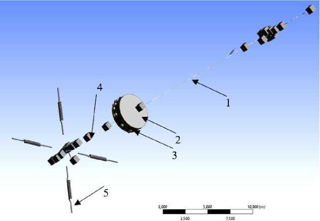
Рис. 1. Общий вид КЭМ балочной РН с исследуемым отсеком:
1 – балочная РН; 2 – воздушная акустическая среда внутри отсека; 3 – корпус отсека с сосредоточенными массами приборов; 4 – сосредоточенные массы установок на РН и заправки её баков; 5 – крепление РН к стартовой площадке через упругие элементы
Fig. 1. General view of the FEM of a beam-type launch vehicle with the compartment under study: 1 – beam-type launch vehicle; 2 – air acoustic environment inside the compartment; 3 – compartment body with concentrated masses of instruments; 4 – concentrated masses of the launch vehicle installations and its fuel tanks; 5 – launch vehicle attachment to the launch pad via elastic elements
Analysis of spatial resonances
To analyze the spectral characteristics of the internal acoustic pressure, the spatial resonances of the cavity under the compartment are calculated. The longitudinal frequencies are calculated by the formula f= fl 2 L ’ where L is the length of the cylinder generator; с is the acoustical velocity, i = 1, 2… To obtain the radial frequencies, the spectral equation can be used:
—Jn ( kR ) + Jn ( kR ) j P c
= 0,
where Z is the cylinder boundary impedance; ρ is the air density; R is the shell; k is the wave number;
Jn ( kR ), Jrn ( kR ) is the Bessel function of the first kind of order n and its derivative n = 0, 1, 2… Figure 2 shows graphs of the functions:
P ( f ) =
Z— J'
Jn j P c
2 n f 2 n f
I R 1 + J„ \ ^-R
\ c J \ c
At the points where the functions intersect the f axis, we obtain its zeros at n = 0, 1, 2, corresponding to the radial frequencies.
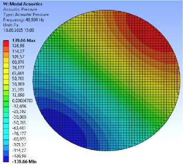
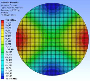
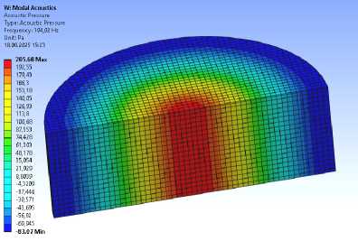
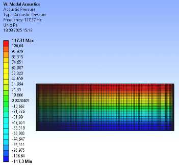
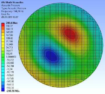
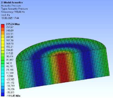
Some spatial longitudinal and radial natural frequencies and mode shapes inside the compartment, obtained using FEM, are shown in Figure 3.
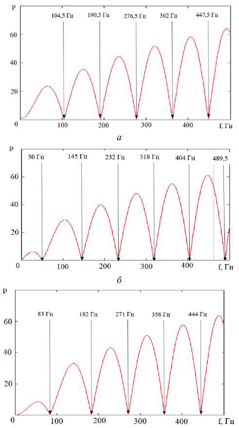
Рис. 2. Графическое получение собственных пространственных частот цилиндрического отсека: а – n = 0; б – n = 1; в – n = 2
Fig. 2. Graphical derivation of natural spatial frequencies of a cylindrical section: a – n = 0; б – n = 1; в – n = 2
From Figures 2 and 3, it can be seen that the first two radial frequencies, 50 and 83 Hz, correspond to the first zeros of the Bessel functions of the first and second order, whereas the first frequency corresponding to zero-order Bessel function is 104 Hz, i.e., the root of the zero-order function is larger than that of the first and second orders. Figure 4 shows the calculated spectrum of low-frequency acoustic pressure p , considering the influence of the LV beam part with the PS operation and the compartment without the beam part rigidly fixed at the end frames. The calculation result for the beam model up to 45 Hz has a sawtooth shape because the vibrations from the PS were specified as vibration displacement values averaged over frequency ranges. According to Figures 2 and 3, it can be concluded that resonance (2) in Figure 4 is due to the radial vibration mode at a frequency of 50 Hz, corresponding to the first root of the first-order Bessel function; resonance (3) arises due to the influence of the radial vibration mode at a frequency of 104 Hz, corresponding to the first root of the zero-order Bessel function; resonance (4) is due to the radial vibration mode at a frequency of 145 Hz, corresponding to the second root of the first-order Bessel function.
а
б
в
г
д
Рис. 3. Пространственные продольные и радиальные собственные частоты и формы колебаний внутри отсека, полученные с помощью КЭМ:
а – первая радиальная частота при n = 1; б – первая радиальная частота при n = 2; в – первая радиальная частота при n = 0; г – первая продольная частота при i = 1; д – вторая радиальная частота при n = 1; е – вторая радиальная частота при n = 0
е
-
Fig. 3. Spatial longitudinal and radial natural frequencies and vibration modes inside the compartment obtained using FEM:
a – the first radial frequency at n = 1; б – the first radial frequency at n = 2;
в – the first radial frequency at n = 0; г – the first longitudinal frequency at i = 1;
д – the second radial frequency at n = 1; е – the second radial frequency at n = 0
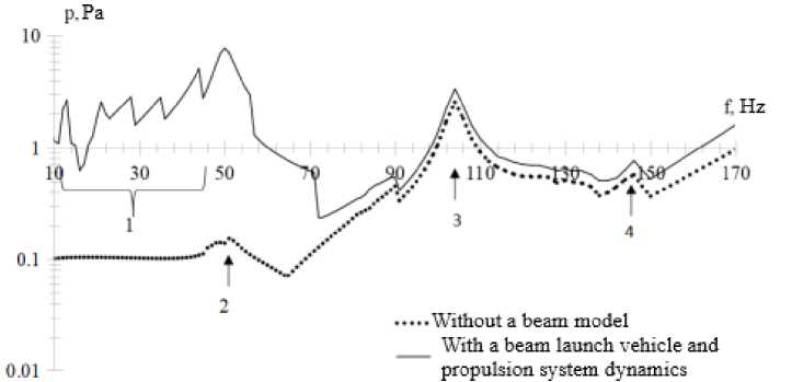
Рис. 4. Расчётный спектр низкочастотного акустического давления внутри отсека с учётом балочной части РН и низкочастотных колебаний, вызванных работой ДУ и отсека без балочной части жёстко зафиксированного на торцевых шпангоутах:
1 – «пилообразная» форма спектра; 2 – резонанс на 50 Гц; 3 – резонанс на 104 Гц; 4 – резонанс на 145 Гц
-
Fig. 4. Calculated spectrum of low-frequency acoustic pressure inside the compartment, considering the LV beam section and low-frequency vibrations caused by the operation of the engine, and the compartment without the beam section rigidly fixed to the end frames:
-
1 – sawtooth spectrum shape; 2 – resonance at 50 Hz; 3 – resonance at 104 Hz; 4 – resonance at 145 Hz
Analysis of structural frequencies
Figure 5 shows the results of analyzing the natural frequencies and their influence on the acoustic pressure inside the LV compartment. Its middle part shows the variation of the difference between adjacent natural frequencies Δ fi = fi +1 – fi from the frequency fi .
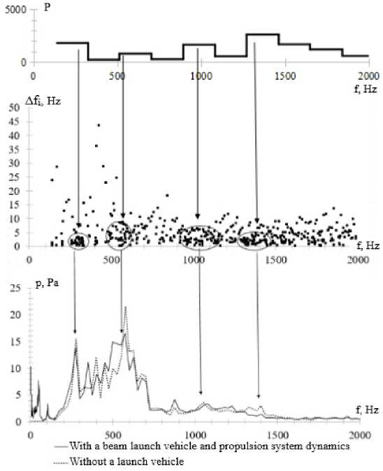
Рис. 5. Результаты анализа обственных частот и их влияние на внутреннее акустическое давление
Fig. 5. Results of the analysis of natural frequencies and their influence on internal acoustic pressure
The lower graph demonstrates the influence of sections with maximum natural frequency density P on the internal acoustic pressure p :
P ( Δ f i , N ) = ∑ i ∆ N f i , (6)
where N is the number of natural frequencies in the frequency range of. The smaller the value Δ f i and the greater the number of natural frequencies N in the frequency ranges of interest, the higher the density P , over the corresponding frequency band where an increase in internal acoustic pressure should occur. Therefore, to analyze the natural frequency density, the operational range from 140 Hz, where the first shell modes appeared, to 2000 Hz was divided into ten equal parts. Then, for each resulting sub-range, P = P (Δ f i , N ) was calculated. The calculation results using formula (6) are presented in the upper part of Figure 5.
From the data presented in Figure 5, it can be noted that resonances in the internal acoustic pressure spectrum near frequencies of 275, 575, 1050, and 1400 Hz are a consequence of increased values of the quantity P.
Influence of boundary conditions on internal acoustic pressure and compartment dynamics
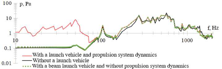
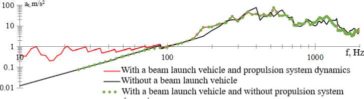
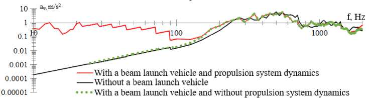
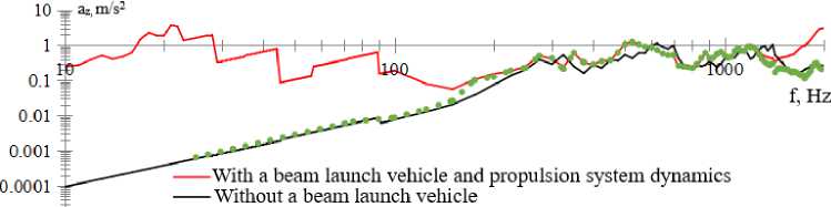
When calculating the vibroacoustic loading of the compartment, three types of boundary conditions were used: 1) compartment without considering the beam-type LV, fixed at the ends of the outer frames; 2) compartment attached to the beam model of the LV, considering the PS dynamics; 3) compartment attached to the beam model of the LV without considering the PS dynamics. The calculation results for the internal acoustic pressure p and vibration accelerations a r , a φ , a z in cylindrical coordinates (r, φ, z) are presented in Figure 6.
The analysis of the results allows for the following conclusions:
-
1) The beam models (with and without considering the PS operation) showed identical values of the studied parameters at high frequencies. At low frequencies up to 80 Hz for parameters R и a r , and up to 150 Hz for parameters a φ and a z , significant discrepancies arise, caused by elastic vibrations of the LV body at low frequencies due to the operation of the PS;
-
2) Comparison of the beam model without considering the PS and the compartment model fixed at the edge frames shows that the corresponding low-frequency parameters become close to each other. Low dynamic activity in the pre-resonance frequency band is typical for closed cylindrical surfaces [5; 15]. However, the sound insulation here is determined not only by stiffness but also by the spatial resonances arising inside the compartment, which reduces its value compared to the case where the compartment surface had absolute sound absorption; in this calculation, it was assumed to be 10% across the entire frequency range [15]. The high-frequency internal acoustic pressure for these cases is comparable. The frequency profile under different attachment methods may change; for example, in the considered case, the vibration loading peaks were redistributed according to the data given in Table 3, while the amplitude characteristics of the vibration accelerations turned out to be comparable. Therefore, for assessing the vibration dynamics of the compartment, it is recommended to use the attached beam model of the LV.
Vibration loading peaks under different compartment attachment conditions
Table 3
|
Vibration Direction |
Peak Frequency without beam LV |
Peak Frequency with beam LV |
|
Radial |
400 Hz, 600 Hz |
525 Hz |
|
Rotational |
500 Hz |
350 Hz |
|
Longitudinal |
625 Hz 1400 Hz |
525 Hz 1200 Hz |
а
б
в
0.00001 i • • • With a beam launch vehicle and without propulsion system dynamics
г
Рис. 6. Результаты расчётов виброакустического нагружения отсека при различных граничных условиях: а – внутреннее акустическое давление; б – виброускорение в радиальном направлении;
в – виброускорение во вращательном направлении; г – виброускоение в продольном направлении
Fig. 6. Results of vibroacoustic loading calculations for a compartment under various boundary conditions: а – internal acoustic pressure; б – vibration acceleration in the radial direction; в – vibration acceleration in the rotational direction; г – vibration acceleration in the longitudinal direction
Conclusion
On the back of the work performed, the following results were obtained:
-
1) vibroacoustic FEM, shown in Figure 1, was developed, consisting of a beam model of the LV, a model of the studied compartment, and the acoustic environment located inside;
-
2) natural frequencies and mode shapes of the medium inside the compartment were obtained. As the calculation results presented in Figures 2–4 show, the primary influence comes from the radial frequencies of 50, 104, and 145 Hz, corresponding to the zero Bessel functions of the zero and first orders;
-
3) to assess the influence of structural frequencies on the vibroacoustic loading of the compartment, a characteristic P for assessing the natural frequency density was introduced according to for-
mula (6). It was shown that there are several ranges in the regions of frequencies 275, 575, 1050, and 1400 Hz where internal acoustic pressure and vibration acceleration values may increase;
-
4) An assessment of the internal acoustic pressure and vibrodynamic parameters of the compartment for different attachment methods was carried out, which showed that low-frequency vibrations can influence the low-frequency internal acoustic pressure of the compartment, which was confirmed during actual rocket operation. The beam model without considering PS vibrations demonstrated the potential influence of the more compliant compartment end frames on the high-frequency dynamics and internal acoustic pressure of the compartment, redistributing the frequencies at which vibration acceleration peaks occurred according to Table 3. Therefore, for the most comprehensive consideration of the influence of various factors on the vibroacoustic loading of a compartment, it is recommended to use an attached beam model of the LV that considers the dynamics of the PS.
Результаты исследования были получены при финансовой поддержке Российской Федерации в лице Минобрнауки России (грант на проведение крупных научных проектов по приоритетным направлениям научно-технического развития, соглашение № 075-15-2024-558).
Acknowledgments
The research results were obtained with financial support from the Russian Federation through the Ministry of Education and Science of Russia (grant for major research projects in priority areas of scientific and technological development, agreement No. 075-15-2024-558).
