Efficient Cosine Modulated Filter Bank using Multiplierless Masking Filter and Representation of Prototype Filter Coefficients Using CSD

Author: Supriya Dhabal, Palaniandavar Venkateswaran
Journal: International Journal of Image, Graphics and Signal Processing(IJIGSP) @ijigsp
Article in issue: 10 vol.4, 2012.
Free access
This paper presents a design of low complexity multichannel Nearly Perfect Reconstruction (NPR) Cosine Modulated Filter Bank (CMFB). CMFBs are used extensively because of ease realization and the inherent advantage of high stop-band attenuation. But, when the number of channel becomes large, it leads to certain limitations as it would require large number of filter coefficients to be optimized and hence longer CPU time; e.g. 32-band or 64-band CMFB. Large number of filter coefficients would also mean that computational complexity of the prototype filter is extremely increased that tends to slow down the convergence to best possible solution. Here, the prototype filter is designed using modified Interpolated Finite Impulse Response (IFIR) technique where masking filter is replaced by multiplier free cascaded structure and coefficients of model filter are converted to nearest Canonical Signed Digit (CSD). The interpolation factor is chosen in such a way that computational cost of the overall filter and different error parameters are reduced. The proposed approach thus leads to reduction in stop-band energy as well as high Side-Lobe-Fall-off-Rate (SLFOR). Three examples have been included to demonstrate the effectiveness of the proposed technique over the existing design methods and savings in computational complexity is also highlighted.
IFIR, SLFOR, CSD, Optimization
Short address: https://sciup.org/15012446
IDR: 15012446
Text of the scientific article Efficient Cosine Modulated Filter Bank using Multiplierless Masking Filter and Representation of Prototype Filter Coefficients Using CSD
Published Online September 2012 in MECS
Perfect Reconstruction Filter Banks (PRFBs) are used extensively in several fields such as speech and image signal processing, data compression techniques, biomedical signal processing, Trans-multiplexer design and also in the field of communications. The theory and design of PRFBs have been widely studied in the previously reported literature [1-3]. Among them Cosine Modulated Filter Bank (CMFB) is an efficient technique, where the filters of analysis and synthesis sections are obtained by simply cosine modulation of a single prototype filter. Due to the cosine modulation, the implementation and design complexities of CMFB are very low compared with other general purpose PRFBs. Thus the design process of whole filter bank reduces to that of the prototype filter and modulation overhead. In CMFB as shown in Fig.1, the input signal is decomposed by M analysis filters H(z) and the outputs are then decimated by a factor of M to obtain M sub-band signals. In the synthesis section, the sub-band signals are upsampled by same factor before passing through the synthesis filters F(z) to reconstruct the original signal. The filter bank will work as perfect reconstruction if the poly-phase components of the prototype filter satisfy some pair-wise power complementary conditions. The optimization of the prototype filter coefficients in this case is highly nonlinear and due to nonlinear optimization conditions, designing general PRFBs is a complicated problem, especially for filter banks with rigid frequency specifications such as sharp cutoff, high stop-band attenuation in case of large number of channels. Therefore, filter banks that structurally satisfies the perfect reconstruction conditions have received considerable attention recently [3].
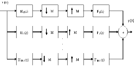
Figure 1. M-channel Maximally Decimated CMFB
CMFBs can be categorized into two major classes: orthogonal and bi-orthogonal CMFBs [4]. In case of orthogonal CMFBs, the prototype filter is a linear phase FIR filter and the reconstruction delay of the filter bank is equal to the prototype filter order. On the other hand, for bi-orthogonal CMFBs, the prototype filter is a nonlinear phase FIR filter and the reconstruction delay can be chosen less than the prototype filter order as low delay CMFBs are highly desirable for any real-time applications [5].
FBs can be further divided into two group’s i.e. Perfect Reconstruction (PR) filter banks and Nearly Perfect Reconstruction (NPR) banks [6, 7]. In PR filter banks, the output signal is a delayed version of the input signal. On contrary, in NPR filter banks the output signal is not exactly same as the input signal i.e. there is a small amount of reconstruction error that is acceptable in most of the practical applications. This error can be minimized by proper choice of the prototype filter and many approaches have been reported to design CMFBs with perfect reconstruction and nearly PR. Recently, second-order cone-programming based algorithms were reported for designing NPR and practically PR filter banks, which can make filter banks extremely close to the PR one [8].
In the least squares method [9], a fourth-order objective function is converted into a quadratic function of the filter coefficients and the objective function is replaced by a summation at a discrete set of frequencies. Hence, the solution obtained actually does not minimize the original objective function. In our proposed technique, the prototype filter is designed using well-known IFIR technique [10,11] which reduces the overall complexity of the prototype filter and performance of the filter bank is improved greatly with very less computations due to less number of filter coefficients to be optimized that also reduces the hardware complexity of the overall filter bank.
The outline of this paper is as follows: The design procedure of the prototype filter for CMFB is described in Section II. In Section III the prototype filter design using IFIR approach is given. Section IV describes the design of image suppressor filter to suppress unwanted replicas and also provide high stop-band attenuation. Representation of filter coefficients using CSD is given in Section V. The proposed algorithm using IFIR approach is presented in Section VI. Three different examples have been taken in Section VII to compare computational complexity of the proposed scheme with existing design methods and hardware requirements with CSD representation is also tabulated. Finally conclusions are drawn in Section VIII.
-
II. D esign of P rototype F ilter
The basic structure of M-channel maximally decimated CMFB is shown in Fig. 1. The reconstructed signal Y(z) can be stated in terms of the input X(z) as follows:
Y(z) = T0(z)X(z) + ME1T1(z)X(zeJ'2 nllM)
l = 1
| M-1 f -j2nl/A whereTl(z) = ^ 2 Fk(z)Hkze /M ,Hk(z) = 2 hk(n)z-n
K = 0 V J
N - 1
and Fk(z) = 2fk(n)z -n n=0
The impulse responses of modulated analysis filters h (n) and synthesis filters f (n) are given by
/
π
hk(n) = 2h(n)cos MM
M
(2.a)
v fk(n) = 2h(n)cos

( к n-kd l+
2 I
v
( -1 ) k 4
J
(2.b)
for 0 ≤ n ≤ N -1 and 0 ≤ k ≤ M -1 where h(n) is the impulse response of the N-length prototype filter H(z) and k is the reconstruction delay. Here T (z) is the overall distortion transfer function and T (z) , l ≠ 0 is the aliasing transfer function. To cancel aliasing and achieve perfect reconstruction, it is required that
T(z) = 0forl = 1,2,_,M-1
and
T0(z) = cz kd , c ^ 0 , k d is a positive integer.
As the analysis and synthesis filters have narrow transition bands and high stop-band attenuation, the overlap between nonadjacent filters is insignificant. Furthermore, it was revealed that significant aliasing terms from the overlap of the adjacent filters are cancelled by choosing 9k = ( 1) k n /4 . In practical applications, the requirements of perfect reconstruction can be relaxed by allowing small amount of error and the filter banks that approximate the perfect reconstruction property can be utilized. Such filter banks, referred to as nearly perfect reconstruction filter banks, are advantageous from the arithmetic complexity point of view. Primarily three types of errors occur at the reconstructed output i.e. amplitude, phase and aliasing distortion. The stop-band attenuation plays an important role in analysis of these parameters. High stop-band attenuation gives in smaller aliasing error but larger reconstruction error. The peak to peak reconstruction and the peak aliasing errors are define as follows [12]:
E
pp
= max i MT0 to v

-min i MT0 to V

E a
I ( Ito
= max| Ei eJ to V v where e| ejto
M - 1
∑T l = 1
1/2

In an approximate reconstruction, aliasing is canceled and the distortion of the overall system is a delay only approximately. Assuming that prototype H(e jω ) filter has linear phase response then the conditions for approximate reconstruction can be stated in terms ofH(ejω ) as follows:
pass-band edge is tuned to minimize the single objective cost function given by the following expression
ф = max ■ го
|H( ra )|2 + H(го -
. for0 < го < —
M) I M
H(ejГО) ^0 for |го| > n/M
T0(ejω)
2M-1
M where Tg(ej™) = E Hl ek = 0 k
j(ω - κπ/Μ)
It has been found that this cost function is convex with respect to the pass-band or cut-off frequency and any reasonable optimization routine will converge to the same global minima regardless of the initial guess of the starting parameters [2].
The accurateness of the first estimation (6) gives aliasing and accuracy of the second (7) gives the reconstruction error. The phase error can be eliminated completely by using linear phase prototype filter. Other two distortion parameters can be minimized by applying suitable optimization technique. Therefore to eliminate amplitude distortion Tq (ej ® ) must be constant for all frequencies i.e.
III. P rototype F ilter D esign U sing IFIR
To design a narrowband low-pass FIR filter, one of the computationally efficient approaches is Interpolated Finite Impulse Response (IFIR) technique [10,11]. In IFIR technique, the desired FIR filter can be implemented as a cascaded form of a model filter with an interpolator. The overall transfer function of the filter H(z) is given by:
H(z) = G(z L )I(z)
E H(ej(®-kn/M) = 1, k = 0
V го e[q,n]
The above condition means that the magnitude squared
response
H(ejω)
is a 2M th band filter [13]. To obtain
high quality reconstruction in a CMFB, the low-pass prototype H( ® ) must satisfy as much as possible two conditions given in [14, 15]:
H( to)2
and
+ H(го - — )2 M
= 1for 0 < го < — M
where G(zL ) is referred as shaping filter shows a periodic frequency response with period 2π/L and is designed to perform transition band shaping. G(zL ) can be realized from a model filter G(z) by replacing each delay element of G(z) with L delay elements where L is the up-sampling factor of the model filter. The transition bandwidth of G(zL ) are 1/Lth of the model filter H(z) . As derived by Mehrnia and Wilson [11], the value of L that will yield minimum number of multipliers is given by the expression
L

+ гos +
V2 П (гos- гоp ) )
I H(ro)| = 0 for го > —
M
The amplitude distortion is eliminated in the combined analysis/synthesis system if (9) is satisfied exactly, while if (10) is satisfied, there is no aliasing between nonadjacent bands. Aliasing between adjacent bands is also eliminated by selecting suitable phase factors in the modulation. Unfortunately, it is not possible to design a finite length filter that exactly satisfies both the constraints, so it is necessary instead to design one that approximately satisfies them. The methods of [1, 3] try to do this directly by combining them into a single cost function and then minimized using the Hookes and Jeaves optimization algorithm. Our method uses the Parks-McClellan algorithm [1] to directly design model filter that approximately satisfy both by varying the passband frequency. Length of the filter, pass-band and stopband error weighting, and stop-band edge are fixed before the optimization procedure is started, while the
Here I(z) is a masking filter or an interpolator which is designed to attenuate the undesired frequency components of G(zL) appears in the stop-band. Consider the design of the prototype filter H(z) having order N and a transition width of A F . If the frequency response of this filter is stretched by a factor of L to obtain filter G(z) then G(z) will have a transition width of L * Af . The order of G(z) will be 1/L times that of H(z) . That is multiplications and additions will now be decreased by a factor of L . To meet the desired specifications take the peak pass-band ripple to be δp /2 for the model filter and for the image-suppressor and the stop-band ripple should not be greater than δs . The length of model filter and image suppressor required filter to meet the frequency domain specifications are given by [10]:
20log 10 δ p δ s -13
N =------—---- + 1
14.36ΔF
where AF = (to p - tos)/2n is the transition bandwidth of the filter.
Now G(zL ) will be a filter having a response similar to H(z) , except for the fact that G(zL) will have replicas at every 2π/L . If we cascade G(zL) with a filter I(z) centered about П , with stop-band edge at (n - to^) the resultant filter will be identical with H(z) and order of the overall filter will be reduced greatly.
H
Let ωpH and ω sH denote the pass-band and stop-band edge of H(z) where toH = п and toH = п . Then the pass-p 2M s M band and stop-band edge of the model filter G(z) will be H
L * to Hand L * to H respectively.
-
IV. D esign of I mage S uppressor F ilter
The image suppressor filter I(z) is also known as masking filter or an interpolator which is designed to attenuate the undesired frequency components in the stop-band of desired prototype filter. Instead of designing the prototype filter to meet (9) and (10) directly, we formulate the prototype filter as an interpolated FIR technique and optimize only the model filter. Here G(z L ) is a model filter to be optimized and I(z) is an interpolator. The magnitude response of G(ej ® ) is designed to be an L -fold stretched version ofH(ej ® ) , while G(ej ® L) is an L -fold compressed version of G(ej ® ) and has a period of 2 п /L .Hence there are one desired pass-band and L - 1 unwanted copies of the desired pass-band inG(ej ® L). The unwanted pass-band can be removed by the low-pass filter I(z) . To obtain multiplier less design of masking filter, I(z) is designed as a cascade combination of one’s i.e.
I(z) = П ( l'(z) ) J
j = 1
where i ' (z) = T z - i • The designed I(z) in this way has a i = 0
high pass-band droop and to eliminate the ripple in passband a sine based compensator has been designed with the corresponding transfer function [6]:
C(z M ) = - 2 - (b + 2)[1 - (2b + 2 + 2)z - M + z - 2M] (15)
or
C(zM) = A[1 + Bz - M + z - 2M] (16)
where A = -2-(b+2),B = -(2(b+2) + 2). The values of m and n are chosen properly so that images produced by G(zL ) can suppress in stop-band to obtain the prototype filter H(z) . A typical magnitude response of compensated image suppressor filter is shown in Fig. 2 where m = n = 8 has been assumed and the compensator parameter to reduce the pass-band droop of I(z) is chosen as b = -5.2, M = 2 . Finally the filter obtained by (15) is cascaded with up-sampled version of model filter according (12) to obtain the prototype filter H(z) .
Magnitude Response (dB)
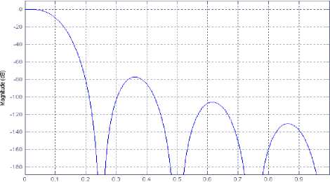
Normalized Frequency (хл rad/sample)
Figure 2. Magnitude Response of Image Suppressor Filter
-
V. CSD R epresentation of M odel F ilter C oefficients
CSD is a minimal signed digit number system which reduces total number of partial product addition in hardware realization of digital multipliers, has found very useful in most of the DSP applications due to low- power, high-speed and area-efficient [15]. The digit set in this form is ternary and each digit can assume -1, 0 or 1. Adjacent CSD digits are never both non zero i.e. the product of adjacent bits are zero d * d ] = 0 . The CSD representation of n bit binary number consists of at most n nonzero digits, whereas in case of 2’s complement form n nonzero digit can be present. It is shown that probability of a digit being zero is roughly 2 for CSD and exactly 1 of 2’s complement. Few decimal numbers are taken in Table I and corresponding 2’s complement with CSD representation is shown below.
TABLE I. T hree bit C anonical S igned D igit N umbers
|
Number |
2’s Complement |
CSD |
|
3 |
011 |
101 |
|
2 |
010 |
010 |
|
1 |
001 |
001 |
|
0 |
000 |
000 |
|
-1 |
111 |
- 001 |
|
-2 |
110 |
010 |
|
-3 |
101 |
101 |
|
-4 |
100 |
- 100 |
Given n digit binary vector B b n — b-'-’b^ O where b i either 0 or 1for0 - i - n - 1. Now it’s corresponding canonical signed digit D = d n-1 ,.„,d 1 d 0 with di = {1,0,1}. An extra bit is appended with B at MSB+1 position i.e. Bn and the value of Bn is 1 if the number is negative otherwise it is 0.
a =£bi*2i =Zdi*2i i=0 i=0
CSD encoding is similar to Booth’s encoding scheme, obtained by taking adjacent digits from LSB to MSB+1 end. If the number is negative the MSB+1 is 1, otherwise it is assumed as zero. The digit b i and bi + 1 are adjacent digit of 2’s complement number and di are corresponding CSD digit. The method of conversion 2’s complement numbers into CSD is given in Table II that can be obtained using following algorithm:
Step1. Start with least significant bit of B by setting the index i = 0 and initial carry c0 = 0.
Step2. Perform addition between adjacent bits bi + l , bi of binary number B with carry in ci and generate the next carry c i + 1 according to the same rule of conventional binary arithmetic addition that is см = 1 if and only if there are two or three 1’s among the three inputs bi + 1, bi andci .
Step3. Generate the ith digit di of vector D by the following arithmetic equation di = bi+ ci— 2ci+1
Step4. Increment the index i by one and check if i = n . If i * n then go step 2, otherwise halt.
For efficient implementation digital filter coefficients are represented to CSD. Depending on above algorithm each coefficient of designed digital FIR filter is replaced by nearest CSD code. The CSD representation of coefficients replaces the multipliers with few summation of partial product. Because the number of nonzero digit is less in case of CSD only multiplication becomes few summation of partial product. For example, 2’s complement of -0.0589 is 1111000011101011.The signed power of 2 representation of -0.0589 is 2—1 + 2—2 + 2—3 + 2-4 + 2—9 + 2—10 + 2—11 + 2—13 + 2—14 + 2—15 . Here number of adder used is 9. But CSD representation of -0.0589 is 00000.000-1000100-101010 and corresponding signed power of two representations is — 2—4 + 2—8 — 2—11 + 2—13 + 2—15 which requires only 2 adders and 2 subtractors. Therefore total hardware is only 4 i.e. saving of 5 hardware’s which in term increases the processing speed of hardware and also reduces the overall cost of filter.
TABLE II. C onversion of 2’ S complement N umbers into CSD
|
carry-in ( c i ) |
bi + 1 |
b i |
carry-out ( c i + 1 ) |
CSD ( di ) |
|
0 |
0 |
0 |
0 |
0 |
|
0 |
0 |
1 |
0 |
1 |
|
0 |
1 |
0 |
0 |
0 |
|
0 |
1 |
1 |
1 |
-1 |
|
1 |
0 |
0 |
0 |
1 |
|
1 |
0 |
1 |
1 |
0 |
|
1 |
1 |
0 |
1 |
-1 |
|
1 |
1 |
1 |
1 |
0 |
-
VI. P roposed A lgorithm
The optimal values of filter coefficients can be computed using a simple linear optimization technique shown in Fig.3. Initially the model filter, up-sampled version of model filter and compensated masking filter is designed using the given specifications and cut–off frequency ( toc ) is iteratively varied to minimize the objective function (11). When the objective function reaches the predefined minimum value (assumed here 10 8 ) the program is terminated and all other filters are designed using modulation of prototype filter.
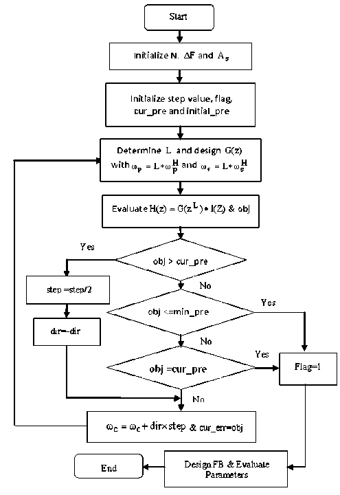
Figure 3. Proposed Algorithm
-
VII. D esign E xamples
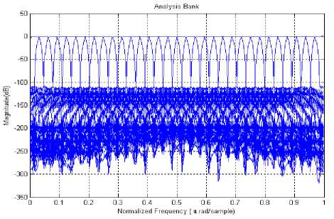
Figure 5. Amplitude Responses of the Analysis Filters
Here performance of the proposed algorithm is carried out via three different design examples and comparison of the proposed technique has been carried out with other existing design methods.
Example1: A thirty two channel cosine modulated filter bank has been designed for same specifications as given in [12, 13] with the stop-band attenuation Ag = 100dB , stop-band frequency mg = 0.03125n . Fig. 4 shows the frequency response of the prototype filter designed using IFIR technique. For the given design parameters, the required model, up-sampled model and interpolator filters are obtained for stretched factor L = 8 . The stop-band attenuation and pass-band ripple for these filters are same as desire in prototype filter. The stop-band frequency of model filter is Ltos = 0.2500n . The obtained magnitude response of the analysis filter bank is shown in Fig. 5. The magnitude responses of amplitude distortion, zoom plot of amplitude distortion and total aliasing distortion are shown in Fig. 6, Fig. 7 and Fig. 8 respectively. Filter coefficients are optimized to reduce the reconstruction error and the obtained values of reconstruction error, aliasing error and the required number of optimized coefficients in proposed IFIR technique are given in Table III. The order of the model filter obtained by the above method is 63. That is only 64 coefficients have to be optimized whereas in [16] the filter has an order of 440 and total distortion was found to be comparable. Therefore the optimization routine is much faster in case of large number of channels as the bandwidth decreases with the increase of number of bands and order of the filters is also increased. Note that the filter is to be designed in each step and hence considerable saving in computation can be obtained when filter order is increased.
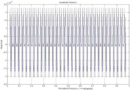
Figure 6. Variation of Amplitude Distortion
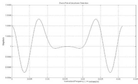
Figure 7. Zoom Plot of Amplitude Distortion
For the IFIR filter the value of L also changes with M, so the filter order remains considerably less than for direct design of filter. The stop-band attenuation obtained is greater than 100dB and the peak to peak amplitude distortion is 1 x 10 - 3 which is comparable with the values obtained in method proposed in [2,8,9,12,13,16].
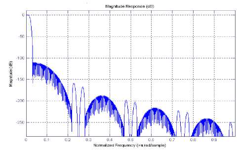
Figure 4. Amplitude Response of the Prototype Filter
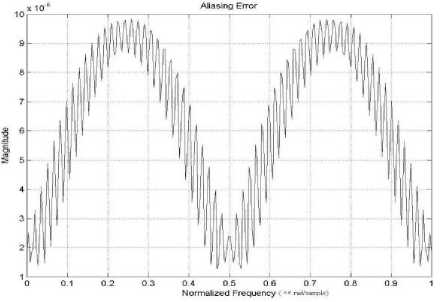
Figure 8. Variation of Aliasing Distortion
TABLE III. P erformance C omparison of 32 B and CMFB
|
Design Method |
Amplitude Distortion |
Aliasing Error |
Optimized Filter Taps |
|
Proposed |
1 x 10 - 3 |
6.715 x 10 - 6 |
64 |
|
[2] |
5.299 x 10 - 3 |
2.586 x 10 - 6 |
512 |
|
[8] |
1.09 x 10 - 3 |
1.40 x 10 - 7 |
448 |
|
[9] |
1.5 x 10 - 3 |
9.45 x 10 - 7 |
448 |
|
[12] |
4 x 10 - 3 |
Not Specified |
482 |
|
[13] |
3.974 x 10 - 3 |
3.8618 x 10 - 7 |
466 |
|
[16] |
3.385 x 10 - 3 |
2.611 x 10 - 7 |
440 |
Example2: A sixty four channel cosine modulated filter bank has been designed with the stop-band attenuation Ag = 100dB and stop-band frequency mg = 0.0155n . For the given design parameters of prototype filter, the required model filter, up-sampled model and interpolator filters are obtained for stretched factor L = 8 . The stop-band attenuation and pass-band ripple for these filters are same as desire in prototype filter. The stop-band frequency of model filter is Lwg = 0.1240n . The magnitude responses of amplitude distortion and aliasing distortion are shown in Fig. 9, Fig. 10 respectively. Filter coefficients are optimized to reduce the reconstruction error and the obtained values of reconstruction error, aliasing error and the required number of multipliers and adders in proposed IFIR technique are summarized in Table IV. The order of the model filter obtained by the proposed technique is 77. That is only 78 coefficients need to be optimized whereas in conventional design method the filter has an order of 511. The obtained values of distortion parameter show good performance than the conventional method.
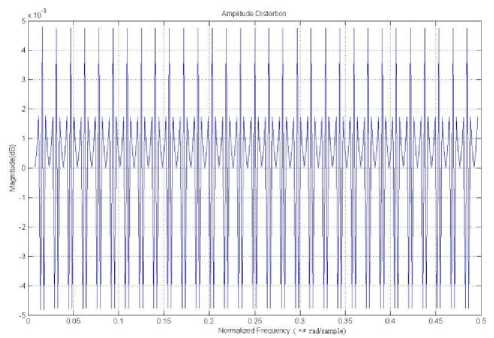
Figure 9. Variation of Amplitude Distortion
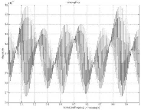
Figure 10. Variation of Aliasing Distortion
TABLE IV. P erformance C omparison of 64 B and CMFB
|
Design Method |
Amplitude Distortion |
Aliasing Error |
Optimized Filter Taps |
|
Proposed |
2.2 x 10 - 3 |
1.58 x 10 - 5 |
78 |
|
Conventional Method |
5.299 x 10 - 3 |
2.586 x 10 - 6 |
512 |
Example3: A seventeen channel cosine modulated filter bank has been designed for same specifications as given in [17, 18] with stop-band attenuation A g = 45 dB , stop-band frequency mg = 0.0588 n . For the given design parameters of prototype filter, the required model, upsampled model and interpolator filters are obtained for stretched factor L = 6 . The stop-band attenuation and pass-band ripple for these filters are same as desire in prototype filter. The stop-band frequency of model filter is Ltog = 0.3528 n . The plot of amplitude distortion and aliasing distortion are shown in Fig. 11 and Fig. 12 respectively. Filter coefficients are optimized to reduce the reconstruction error and the obtained values of reconstruction error, aliasing error and the required number of optimized filter coefficients in proposed IFIR technique are given in Table V. The order of the model filter obtained by the above method is 31. That is only 32 coefficients have to be optimized whereas in method [17] the filter has an order of 101. The corresponding result shows amplitude distortion is very less compared to other design methods [17, 18] but the aliasing error is little bit larger that mainly arises due to high stop-band attenuation of masking filter.
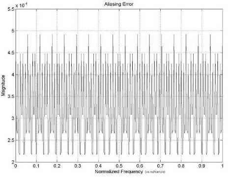
Figure 12. Variation of Aliasing Distortion
TABLE V. P erformance C omparison OF 17 C hannel CMFB
|
Design Method |
Amplitude Distortion |
Aliasing Error |
Optimized Filter Taps |
|
Proposed |
1.2 х 10 - 3 |
9.9 х 10 - 3 |
32 |
|
[17] |
6.79 х 10 - 3 |
3.794 Х 10 - 4 |
101 |
|
[18] |
5.9566 х 10 - 3 |
3.8948 x 10 — 4 |
102 |
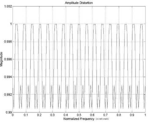
Figure 11. Variation of Amplitude Distortion
TABLE VI. P erformance with CSD R epresentations
|
17 Bands |
32Bands |
64 Bands |
|
|
Optimized Filter Taps |
32 |
64 |
78 |
|
Stop-band a ttenuation ( A s ) |
75dB |
50dB |
60dB |
|
Number of Iterations |
25 |
30 |
74 |
|
Adder/Subtractor |
109 |
158 |
261 |
|
Amplitude d istortion ( Epp ) |
5.7 х 10 -3 |
3.8 х 10 - 3 |
5.1 х 10 - 3 |
|
Aliasing d istortion ( E ) a |
7 х 10 -4 |
6.4 х 10 - 3 |
1.7 х 10 - 3 |
In each iteration the prototype filter coefficients are converted to nearest CSD format and optimization routine terminates when near perfect reconstruction is achieved. The details of three examples have been shown in Table VI. It is observed that very less number of filter coefficients has to be optimized and Number of Iterations (NOI) is also less i.e. the computational complexity is reduced greatly although the performance parameters are almost same for all the cases. Due to CSD conversion the stop-band attenuation of prototype filter is reduced but this may be acceptable in most of the practical applications.
-
VIII. C onclusion
In this paper, a new technique for efficient implementation of NPR cosine modulated filter banks is presented and prototype filter coefficients are converted to minimal signed digit representation to obtain multiplier-less filter bank. The unconstrained objective function is formulated using perfect reconstruction condition and prototype filter has been designed by varying the cut-off frequency to obtain best possible solution. The main advantage of proposed method is that the masking filter required to suppress unwanted passband during up-sampling operation is completely multiplier-less which provides significant savings in computational cost as well as improvement in SLFOR of the prototype filter. The obtained values of reconstruction and aliasing errors are comparable with the already existing methods for given specifications. It is also observed that the proposed algorithm converges very fast in low number of iterations and can be effectively used for filters with large number of bands. Using this approach, the system complexity in terms of number of multipliers reduces greatly but the group delay of the overall prototype filter is remained same that can be reduced with the appropriate choice of up-sampling factor L . Therefore this method will be useful in several applications such as audio signal processing and image compression technique.
References Efficient Cosine Modulated Filter Bank using Multiplierless Masking Filter and Representation of Prototype Filter Coefficients Using CSD
- J. D. Johnston, “A filter family designed for use in quadrature mirror filter banks”, in Proc. IEEE Int. Conf. Acoust., Speech, Signal Processing, 1980, pp. 291-294.
- C.D. Creusere and S.K. Mitra, “A Simple method for designing high quality prototype filters for M-band pseudo QMF banks”, IEEE Trans. on Signal Processing, Vol 43, pp.1005-1007, April 1994.
- Troung Q, Nguyen, “Near-perfect-reconstruction pseudo-QMF banks”, IEEE Trans. on Signal Processing, Vol. 42, no. 1, pp. 65-76, 1994.
- M. B. Furado, P. Diniz, S. L. Netto and T. Saramaki, “On the Design of High-Complexity Cosine-Modulated Trans-multiplexers Based on the Frequency-Response Masking Approach,” IEEE Trans. on Circuits and System, Vol. 52, No. 11, Nov. 2005, pp. 2413-2426.
- Felicja W. Schillak, “Design of Low-Delay Cosine-Modulated Filter Banks with Equiripple Reconstruction Error”, International Conference on Signals and Electronics Systems, Sept. 14-17, 2008.
- Dhabal S, Chowdhury S.M.L, Venkateswaran P. , "A novel low complexity multichannel Cosine Modulated Filter Bank using IFIR technique for Nearly Perfect Reconstruction," Recent Advances in Information Technology (RAIT), pp.208-213, 15-17 March 2012
- R. Bregovic and T. Saramaki, “An efficient approach for designing nearly perfect-reconstruction low-delay cosine-modulated filter banks”, IEEE ISCAS, May 2002, vol. 1, pp. I–825–I–828.
- W. S. Lu, T. Saramaki, and R. Bregovic, “Design of practically perfect- reconstruction cosine modulated filter banks: A second-order cone programming approach”, IEEE Trans. Circuits Syst., Reg. Papers, vol. 51, no. 3, pp. 552–563, Mar. 2004.
- A. Kumar, G.K.Singh, R.S.Anand, “A simple design method for the cosine-modulated filter banks using weighted constrained least square technique”, Journal of the Franklin Institute, 606–621.
- Y. Neuvo, C. Y. Dong and S. K. Mitra, “Interpolated Finite Impulse Response Filters”, IEEE Transactions on Acoust, Speech, Signal Processing, Vol. ASSP-32, June 1984, pp. 563-570.
- A. Mehrnia and J. A. Willson, “On Optimal IFIR Filter Design”, IEEE Proceedings of the 2004 International Symposium on Circuits and Systems, Vol. 3, May 2004, pp. 133-136.
- Neela Rayavarapu, Neelam Rup Prakash, “An Efficient IFIR Filter Based Prototype Filter Design for Cosine Modulated Transmultiplexers”, 2010 International Conference on Signal Acquisition and Processing.
- Yuan-pei Lin and P.P. Vaidyanathan, “A Kaiser Window approach for the design of prototype filters of cosine modulated filter banks”, IEEE Signal Processing Letters, vol5, pp.132-134, June 1998.
- R.K.Soni, A. Jain, R. Saxena, ”Design of M-Band NPR Cosine- Modulated Filter bank Using IFIR Technique”, Journal of Signal and Information Processing, 2010, 35-43.
- R.M.Hewlitt and E.S. Swartzlantler, “Canonical signed digit representation for FIR digital filters”, in Proc. IEEE Workshop on Signal Processing Systems (SiPS 2000), pp. 416-426, 2000.
- F. Cruz-Roldan,, P. A. López, S. M. Bascón and Stuart S. Lawson, “An Efficient and Simple Method for Designing Prototype Filters for Cosine-Modulated Pseudo-QMF Banks”, IEEE Signal Processing Letters, vol.9, no.1, Jan 2002, pp. 29-31.
- P. Vaidyanathan, Multirate Systems and Filter Banks. Englewood Cliffs, NJ: Prentice-Hall, 1993.
- H. H. Kha, H. D. Tuan and T. Q. Nguyen, “Efficient Design of Cosine-Modulated Filter banks via Convex Optimization” IEEE Trans. on Signal Processing, Vol.57, No. 3, Mar. 2009, pp. 966-976.
