Efficient Image Steganogrphic Algorithms Utilizing Transforms: Wavelet and Contourlet with Blowfish Encryption

Автор: Saddaf Rubab, Younus Javed
Журнал: International Journal of Computer Network and Information Security(IJCNIS) @ijcnis
Статья в выпуске: 2 vol.7, 2015 года.
Бесплатный доступ
Steganography is a means to hide the existence of information exchange. Using this technique the sender embeds the secret information in some other media. This is done by replacing useless data in ordinary computer files with some other secret information. The secret information could be simple text, encoded text or images. The media used as the embedding plane could be an image, audio, video or text files. Using steganography ensures that no one apart from the sender and the receiver knows about the existence of the message. In this paper, a steganography method based on transforms used i.e. Wavelet and Contourlet. Devised algorithm was used against each transform. Blowfish Encryption method is also embedded to double the security impact. The major advantage of applying transforms is that the image quality is not degraded even if the number of embedded characters is increased. The proposed system operates well in most of the test cases. The average payload capacity is also considerably high.
Steganography, PSNR, blowfish, Huffman, DCT, DWT
Короткий адрес: https://sciup.org/15011382
IDR: 15011382
Текст научной статьи Efficient Image Steganogrphic Algorithms Utilizing Transforms: Wavelet and Contourlet with Blowfish Encryption
Published Online January 2015 in MECS DOI: 10.5815/ ijcnis.2015.02.02
The art of hiding information in some other media of information is known as steganography. The secret information is embedded into another media in such a way that no one else than sender and propspective reciever can know about the presence of the secret information. In other words, using this technique even obscure that a secret information is being transmitted [1].
-
A. Encoding schemes
-
1. Huffman
In the past years, researchers give more attention to variable length codes among the numerous encryption algorithms including DES [2], AES [3], and Triple DES [2]. Huffman code is a mapping method for symbols to bits of variable length like arithmetic coding and Lempel-Ziv coding. David A. Huffman in 1952 [4], a PhD student at MIT introduced this encoding scheme mainly for the purpose of lossless data compression.
-
2. Blowfish
It gives memory management by using few locations/bits. As an intermediate output it generates a binary tree using symbols and sometimes letters with their respective frequencies in ascending or descending order. The sum of smallest frequencies is assigned to parent node, and this continues until we are left with only the root node. To translate the codes, 0’s and 1’s (binary digits) are assigned to all nodes and read from leaf to root node. The output is tabulated in Huffman Table. Huffman codes provides better safeguard to secret data from any third party attacks.
Bruce Schneier, a cryptologist, designed a 64-bit block cipher and variable length key and produced with the name Blowfish. The process is divided in two parts i.e. the expansion of key and encryption of data. It is widely used to reduce the repeating information resulting in increased contrast image. Blowfish will be used in our proposed method for data encryption because its performance outshines if paralleled with other encryption algorithms like AES, DES [1].
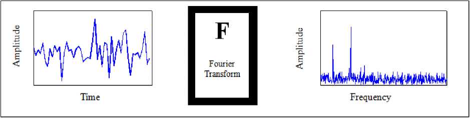
Fig 1: Short-Time Fourier Transform of a Signal
-
II. Background And Related Work
Hiding data methods involving Least Significant Bit (LSB) of images are more prone to detection of any secret data. Steganographic techniques proposed involve transforms of image like Fourier and Discrete Cosine Transform (DCT), which makes the data to be more resistant from becoming corrupted [5]. In DCT methods, it is possible to recover data even if some image data is lost or altered by any third party [8]. DCT modulates atleast two coefficients of an image block to stegan the information [6]. Fourier Transform work on the same principles of DCT, by modifying coefficients of mid band frequencies [7]. Following sections shall give the detailed description for wavelet and contourlet transforms:-
-
A. Wavelet Transform
Wavelets’ history is not timeworn, but it had a great interest of researchers who boosted the wavelet transform information in their articles. Fourier set the basis of the frequency which for a long time was the best and the only approach existent in signal analysis. The research gradually moved from frequency based analysis to scale based analysis when the researchers realized that an approach measuring average fluctuations at different scales might prove less sensitive to noise. And so, the wavelet transform was born. The first recorded mention of what we call now a “wavelet” dates back to 1909 in Alferd Haar’s thesis [9]. The concept of wavelets in its present theoretical form was proposed later by Morlet. The main algorithm using filters was provided by Stephane Mallat [10] in 1989. Since then, the research has become international. The Mallat algorithm is in fact a classical scheme known in the signal processing community as a two channel subband coder [10].
The requirement of varying window size was fulfilled by wavelet analysis which offers a windowing technique with variable sized window. The wavelet transform allows the use of long time intervals where we want more precise low frequency and short intervals where we want high frequency information.
coefficients were abandoned. This presented a novel technique using DWT transform for the cover image transformation and then Huffman is used on secret message before embedding. It uses only high frequency coefficients for embedding message bits and neglected low ones to get better image quality.
M. F. Tolba, M. A. Ghonemy, I. A. Taha, and A. S. Khalifa in 2004 [16] proposed an algorithm using wavelet transforms and make use of wavelet coefficients. This technique embeds message bitstream to the Least Significant Bit (LSB) of wavelet coefficients generated by wavelet transform of colored cover image. Results displayed the high invisibility of the proposed model even with large message size.
Bo Yang and Beixing Deng in 2006 [17] presented an image steganographic scheme for gray scale images. This scheme hides a small gray size image in a large one. Input image is first transformed using Arnold transformation to preserve large area information in cover image. Arnold is a tool converting one matrix into another. Suppose A be MxM matrix, a point (i0, j0) can be shifter to (i, j) by using:
i 0
j 0
1 i
2 j
(Mod M )
DWT is then performed on cover image in which small image is encoded and also on Arnold transformed image. Next step performs the bit streaming of DWT coefficients to embed the approximate component of secret image into the approximate component of cover image using LSBs. This work also claimed that original image is not required in extraction process.
B. Contourlet Transform
The wavelet transform cannot represent image edges and discontinuities which were overcome by the recently proposed contourlet transform. Contourlet transform provides directionality and anisotropy features, besides retaining the desirable characteristics of wavelet transform, such as multi-resolution and localization.
Recent researches’ have identified that the main cause of inefficiency is the lack of directionality and anisotropy and also described bi-dimensional smooth contours, and how new transforms, instead, aspire to these features. In the last years a lot of different transforms have been proposed (contourlets [11], directionlets [12], curvelets [13], bandelets [14], etc.), to remove limits of image
contours representation. These all were theoretical results but more convincing to develop coding algorithms. Directionality and anisotropy are the prominent features of contourlet transform [11] that influence our selection of transform as part of our proposed algorithm. It is also easy to implement using filter bank. Slight redundancy is the only known drawback of contourlet transform which is not a big issue in low bit-rate coding [18].
Do and Vetterli in 2005 [11] introduced contourlet transform; consisting, a Laplacian pyramid and a directional filter bank (DFB). The Laplacian pyramid (LP) was proposed by Burt and Adelson [19] in 1983 as a multi-resolution image representation. In the first stage of the decomposition, the original image is transformed into a coarse signal by mean of a low pass filtering and a down sampling. This coarse version is then up-sampled and filtered to predict the original image. This procedure can be repeated iteratively in order to obtain a multiresolution decomposition. LP decomposition is a redundant representation so it is natural to wonder why in contourlet it has been preferred to critically sampled filter banks as discrete wavelet transforms. The motivation must be detected in the successive use of Laplacian pyramid; in fact, in contourlet decomposition, a directional filtering is performed on the bandpass versions of input signal. So it needs a decomposition that permits further subband decomposition of its bandpass images. To this target the LP has two advantages over the critically sampled wavelet scheme: first, it generates only one bandpass version, second, it does not suffer from the frequencies “scrambling”. This problem arises in the critical sampling filter banks when, because of down sampling, the high pass channel is folded back into the low frequency band and its spectrum is reflected [21]. This problem is overcome in LP by downsampling only the low pass channel. A peculiarity of LP used in contourlet transform is the reconstruction structure.
Hedieh Sajedi, Mansour Jamzad in 2009 [20] proposed a method called ContSteg to embed the information in 4x4 blocks of contourlet subbands by exchanging the value of two coefficients in a block of contourlet coefficients. Hedieh Sajedi, Mansour Jamzad in 2010 [23] presented a contourlet based image steganographic method to hide secret information in a cover image. Presented work decomposed cover image using contourlet transform and then embed information by increasing and decreasing the value of a coefficient in a subband obtained by contourlet decomposition. This paper presented the comparative study of effect of cover image on embedding and suggested that choosing proper cover image would decrease the chances of detectability.
-
III. Proposed Method
Every time researchers have very limited parameters to play within when proposing a new algorithm. In image steganography the main parameters to focus on are:-
-
a. Robustness
-
b. Security
-
c. Capacity
The problem in image steganography is to minimize the chances that the presence of hidden/secret message is identified. There is a tradeoff between the making image imperceptible and the embedding capacity of the stego-image, for a given cover image. By increasing the capacity, image quality is degraded and invisibility is not achieved. By maximizing imperceptibility, the embedding capacity is reduced.
Algorithm has been implemented in MATLAB 7.9 and Visual Studio 2010. Devised method consists of two main processes. First one deals with the MATLAB implementation which passes some controls to Visual Studio 2010 for C# implementation of blowfish algorithm. The other process then returns back the control to MATLAB from Visual Studio 2010. Main steganographic routines have been developed in MATLAB using wavelet toolbox functions and Blowfish algorithm for enhanced security in C# using Visual Studio 2010. Following is the pseudo code:
Step 1: image histogram test
Input: Cover image
Output: Cover image
Action: If the cover image passes the histogram test Then accept the cover image
Else search for another cover image.
Step 2: image corrections
Input: Cover image
Output: Processed cover image
Action: For each pixel of cover image apply level, contrast and balance corrections
Step 3: Apply wavelet transform
Input: Processed cover image
Output: Transformed image
Action: Apply 2D wavelet transform
Step 4: Calculate threshold (Th)
Input: Transformed image
Output: number of pixels can be changed (n), DWT of the cover image
Action: Calculate Th
Th = (correlation factor/Number of coefficient) ∑ (mod value of all 2D wavelet coefficients)
Select DWT coefficient of every pixel in cover image if coefficient value < Th then keep coefficient index and n=n+1
Step 5: Message encryption process
Input: Information
Output: encrypted information
Action: Pass control from Matlab 7.9 to Visual Studio 2010
Encrypt information with Blowfish
Pass control back to Matlab
Step 6: Bit streaming
Input: n, encrypted information
Output: 1D bit streamed information
Action: convert the encrypted information to 1D bit stream using n
Step 7: 2D wavelet transform of encrypted information
Input: encrypted bit stream of the message
Output: DWT transform of the encrypted message.
Action: transform the encrypted bit stream of the message to Wavelet domain
Step 8: Coefficient placement
Input: 2D wavelet transform of cover image and 2D wavelet transform of the encrypted information.
Output: stego image
Action:
-
a. Put coefficients of wavelet transform of encrypted information in the indexes stored in Step 4.
-
b. Perform inverse wavelet transform.
This algorithm accepts the input cover image format and input information to be encoded. It then processes the Function hist on input cover image and returns 1 if test is passed and 0 otherwise. The next step is image preprocessing, which is performed using Fucntion imagecorrection . This function accepts the tested cover image and performs following three (03) preprocessing functions:
-
a. level correction
-
b. contrast correction
-
c. balance correction
The above three functions have been performed using image processing toolbox. The next step as also explained in flow chart is to get wavelet coefficients. This task is done by using Function 2dwt . In the proposed algorithm, Symlet wavelet has been used. It accepts the corrected image and performs wavelet functions using the wavelet toolbox.
The transformed cover image or coefficients are passed to Function thresh and it processes the inputs using (2):
Th = (correlation factor/Number of coefficient) ∑ (mod value of all 2D wavelet coefficients) (2)
It returns the number of pixels that can be changed (n).
The second phase of the algorithm deals with the input message. The input message has been accepted using MATLAB 7.9. Now it is passed to Blowfish encryption algorithm using MEX file implemented in C Sharp or C#. The blowfish algorithms encrypts the message and sends the control back to MATLAB program with the processed input message which is now an encrypted one.
The encrypted message and the number of pixels (n) are now passed to Function bit_stream for converting the encrypted message to 1D bit stream using n. This bit stream is then used with the wavelets to get it transformed into wavelet domain using wavelet toolbox.
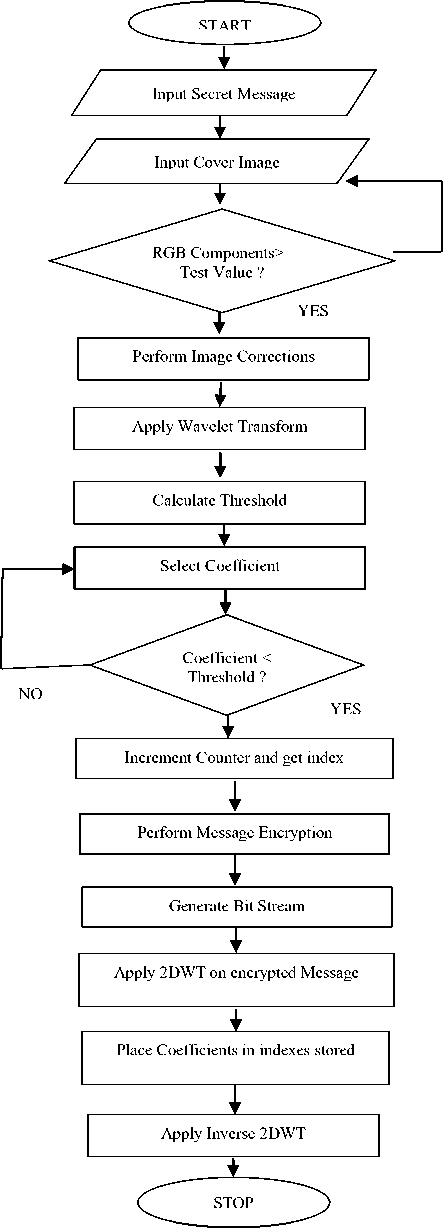
NO
Fig 2: Flowchart of proposed algorithm
The transformed cover image and transformed message bit stream have been further processed. In this step, the coefficients of wavelet transform of encrypted message are placed in to the indexes stored earlier in ‘n’ of the transformed cover image. At end the inverse wavelet transform is performed.
The blowfish algorithm has been implemented in C Sharp or C# using Visual Studio 2010 on Windows 7 Platform. It has been called by ALGO A and ALGO B using MEX file. Following is the detail of algorithm:-
The MATLAB code passed input message only to the Blowfish. It stores this information as its one of the inputs. The other input is a 128 bit Blowfish key which has been used for encryption. There are two options, either to load it from a file or to generate it. Using the enrption key, P-box has been generated in the form of an array consisting of 18 words, where each word is of 32 bits. The other S-box array has been generated by using the encryption key by repreated application of the Blowfish algorithm itself. The size of this array is 4x256 words, where each word is 32 bits long. There is another array used to store the Blowfish key. In this, each element is a 32 bit word and for a 128 bit key, the array has four elements. To check whether encryption key has been loaded yet or not, a boolean variable has been used to keep track of it.
This algorithm has been programmed using Electronic Code Book (ECB) of Blowfish encryption. In this mode, the data from the input file is divided into data blocks of 64 bits each. Then each data block is encrypted and writes it to the output file for MATLAB code. The data block encryption has been done with the number of rounds.
The decoding phase first take the stego image and then employs inverse wavelet transform on it. After getting inverse of wavelet transform the processed data has been passed to extraction module. This module results in bit stream and cover image. The obtained bit stream is decrypted by using the decryption module of Blowfish to get input plain text that was encoded.
-
IV. Results
The performance of the proposed algorithm using wavelet and contourlet transforms has been measured by using following three sets of image sizes; each contains ten (10) colored images:
-
a. 256x256
-
b. 306x648
-
c. 512x512
The reason for selecting the above image sizes is that the performance has been improved against the work presented by Ali Al-Taby in [22] and in [22] the image size taken was 306x648. Other image sizes have also been collected to check the trend. These input test images used as cover images vary from complex to smooth ones. To show the distortion of the final stego image, Peak Signal to Noise Ratio (PSNR) and Mean Squared Error (MSE) is used with the payload. Payload is calculated as the total number of bits that can be embedded into the number of bits of input cover image. It varies with the smoothness of an image. The payload value is taken in percentage (%). The PSNR is actually the ratio of maximum possible power of signal and the power of noise that can affect the reliability of signal. It is expressed in logarithmic decibels because most of the signals have very wide dynamic range. The higher the value of PSNR, the better is the performance. It can easily be calculated using MSE which is defined for two i x j images as given in (1) and (2):-
MSE= ∑ ^0 ∑ j=0 ( Xij - Xij ) (3)
PSNR (dB) = 10log 10 ( ) (4)
X ij represents the ith rows and jth columns of original image and Xi j represents the ith rows and jth columns of transformed image. Higher the PSNR value means more difficult to perceive that any hidden message is hidden.
Correlation factor (α) is a statistical measure of interdependence between two variables. It measures the strength of straight line or linear relationship between two variables. It takes on values ranging from -1 to +1. Correlation factor is used to calculate the threshold value.
In the experiments performed, input text information is taken as user’s message and embedded into each of the input cover images. The input information is in Microsoft Word file (.doc/.docx) and is processed by C # MEX file. This file consists of combination of characters, numeric values, and special characters. Experiments have been performed by varying the correlation factor and input cover images of three different sizes. In each experiment, Symlet 4 wavelet family has been used. All of these experiments make use of horizontal, vertical and diagonal details and approximation details of level 3 decomposition. The details of these experiments are given experiment wise. Taking a single image for each experiment, both transforms have been executed and results have been tabulated to give a comparison.
Table 1: Image Name MASK
|
Wavelets |
Contourlets |
||||||
|
Image Size |
Correlation Factor (a) |
MSE (%) |
Payload (%) |
PSNR (dB) |
MSE (%) |
Payload (%) |
PSNR (dB) |
|
256x256 |
0.1 |
0.35 |
30.28 |
50.67 |
0.3 |
30.28 |
52.17 |
|
0.2 |
0.44 |
40.17 |
48.21 |
0.41 |
40.17 |
49.71 |
|
|
0.3 |
0.57 |
44.83 |
45.02 |
0.54 |
44.83 |
46.52 |
|
|
0.4 |
1.46 |
51.28 |
42.21 |
1.43 |
51.28 |
43.71 |
|
|
0.5 |
1.92 |
55.69 |
39.67 |
1.89 |
55.69 |
41.17 |
|
|
0.6 |
2.56 |
62.8 |
32.81 |
2.53 |
62.8 |
34.31 |
|
|
0.7 |
3.47 |
64.72 |
30.97 |
3.44 |
64.72 |
32.47 |
|
|
0.8 |
4.68 |
67.47 |
28.77 |
4.65 |
67.47 |
30.27 |
|
|
0.9 |
6.19 |
69.21 |
24.32 |
6.16 |
69.21 |
25.82 |
|
|
1 |
7.74 |
72.02 |
22.01 |
7.71 |
72.02 |
23.51 |
|
|
306x648 |
0.1 |
0.39 |
38.42 |
51.67 |
0.32 |
38.42 |
53.37 |
|
0.2 |
0.57 |
42.73 |
50.2 |
0.5 |
42.73 |
51.9 |
|
|
0.3 |
0.72 |
49.97 |
48.01 |
0.65 |
49.97 |
49.71 |
|
|
0.4 |
1.28 |
56.89 |
46.32 |
1.21 |
56.89 |
48.02 |
|
|
0.5 |
1.96 |
61.96 |
42.61 |
1.89 |
61.96 |
44.31 |
|
|
0.6 |
2.81 |
65.88 |
39.58 |
2.74 |
65.88 |
41.28 |
|
|
0.7 |
3.76 |
69.07 |
37.05 |
3.69 |
69.07 |
38.75 |
|
|
0.8 |
4.97 |
71.64 |
34.85 |
4.9 |
71.64 |
36.55 |
|
|
0.9 |
6.28 |
73.86 |
32.87 |
6.21 |
73.86 |
34.57 |
|
|
1 |
7.94 |
74.54 |
28.96 |
7.87 |
74.54 |
30.66 |
|
|
512x512 |
0.1 |
0.421 |
42.41 |
54.68 |
0.331 |
42.41 |
56.58 |
|
0.2 |
0.58 |
46.73 |
52.2 |
0.49 |
46.73 |
54.1 |
|
|
0.3 |
0.81 |
51.12 |
49.18 |
0.72 |
51.12 |
51.08 |
|
|
0.4 |
1.34 |
57.86 |
48.58 |
1.25 |
57.86 |
50.48 |
|
|
0.5 |
2.02 |
63.46 |
44.21 |
1.93 |
63.46 |
46.11 |
|
|
0.6 |
2.88 |
66.51 |
40.46 |
2.79 |
66.51 |
42.36 |
|
|
0.7 |
3.91 |
71.64 |
38.68 |
3.82 |
71.64 |
40.58 |
|
|
0.8 |
5.07 |
74.06 |
36.22 |
4.98 |
74.06 |
38.12 |
|
|
0.9 |
6.39 |
76.94 |
34.73 |
6.3 |
76.94 |
36.63 |
|
|
1 |
7.46 |
79.56 |
31.15 |
7.37 |
79.56 |
33.05 |
|
In Table 1 input cover image ‘MASK’ is used with increased values of correlation factor, which in turn decreases the PSNR value. If 512x512 image size is considered for comparisons with correlation factor 0.2, the Wavelets gives PSNR value equals to 52.2 and 54.10 as PSNR value using the Contourlets for the same correlation factor and image size. It concludes that the contourlet transform results in better image quality than wavelet transform if the image size and payload remains constant.
Repeating the same performance evaluation experiments for the image ‘BUILDING’ of size 256x256 and correlation factor 0.4, Wavelets gives PSNR value equals to 42.59 and Contourlets gives 44.09 as PSNR value for the same correlation factor and image size. PSNR value deteriorates as correlation factor increases and keeping the image sizes same. The comparisons for both transforms for image name ‘BUILDING’ have been tabulated in Table 2. It has been concluded that contourlets gives constantly better performance than wavelets.
Table 2: Image Name BUILDING
|
Wavelets |
Contourlets |
||||||
|
Image Size |
Correlation Factor (α) |
MSE (%) |
Payload (%) |
PSNR (dB) |
MSE (%) |
Payload (%) |
PSNR (dB) |
|
256x256 |
0.1 |
0.4 |
34.14 |
50.75 |
0.35 |
34.14 |
52.25 |
|
0.2 |
0.54 |
40.02 |
48.29 |
0.51 |
40.02 |
49.79 |
|
|
0.3 |
0.69 |
45.15 |
45.1 |
0.66 |
45.15 |
46.6 |
|
|
0.4 |
1.9 |
51.27 |
42.59 |
1.87 |
51.27 |
44.09 |
|
|
0.5 |
1.92 |
55.82 |
38.8 |
1.89 |
55.82 |
40.3 |
|
|
0.6 |
2.77 |
63.06 |
32.53 |
2.74 |
63.06 |
34.03 |
|
|
0.7 |
3.54 |
64.51 |
30.16 |
3.51 |
64.51 |
31.66 |
|
|
0.8 |
4.95 |
67.55 |
27.4 |
4.92 |
67.55 |
28.9 |
|
|
0.9 |
6.21 |
69.29 |
24.41 |
6.18 |
69.29 |
25.91 |
|
|
1 |
8 |
72.21 |
22.28 |
7.97 |
72.21 |
23.78 |
|
|
306x648 |
0.1 |
0.41 |
38.49 |
51.74 |
0.34 |
38.49 |
53.44 |
|
0.2 |
0.64 |
42.8 |
49.27 |
0.57 |
42.8 |
50.97 |
|
|
0.3 |
0.79 |
50.04 |
47.09 |
0.72 |
50.04 |
48.79 |
|
|
0.4 |
1.35 |
56.96 |
45.39 |
1.28 |
56.96 |
47.09 |
|
|
0.5 |
2.01 |
62.03 |
42.68 |
1.94 |
62.03 |
44.38 |
|
|
0.6 |
2.84 |
65.95 |
39.65 |
2.77 |
65.95 |
41.35 |
|
|
0.7 |
3.8 |
69.14 |
37.12 |
3.73 |
69.14 |
38.82 |
|
|
0.8 |
4.71 |
71.72 |
34.92 |
4.64 |
71.72 |
36.62 |
|
|
0.9 |
6.29 |
73.93 |
32.94 |
6.22 |
73.93 |
34.64 |
|
|
1 |
7.92 |
74.91 |
28.03 |
7.85 |
74.91 |
29.73 |
|
|
512x512 |
0.1 |
0.46 |
32.21 |
54.82 |
0.37 |
32.21 |
56.72 |
|
0.2 |
0.63 |
40.09 |
52.36 |
0.54 |
40.09 |
54.26 |
|
|
0.3 |
0.76 |
49.56 |
51.17 |
0.67 |
49.56 |
53.07 |
|
|
0.4 |
1.66 |
53.34 |
48.73 |
1.57 |
53.34 |
50.63 |
|
|
0.5 |
1.93 |
55.57 |
43.87 |
1.84 |
55.57 |
45.77 |
|
|
0.6 |
2.84 |
64.13 |
42.96 |
2.75 |
64.13 |
44.86 |
|
|
0.7 |
3.81 |
65.58 |
39.12 |
3.72 |
65.58 |
41.02 |
|
|
0.8 |
5.02 |
67.62 |
37.47 |
4.93 |
67.62 |
39.37 |
|
|
0.9 |
6.28 |
69.36 |
34.48 |
6.19 |
69.36 |
36.38 |
|
|
1 |
8.07 |
72.17 |
32.09 |
7.98 |
72.17 |
33.99 |
|
It has been observed from Table 3 that image name ‘STAIRS’ is used for simulating results and as we keep on increasing the correlation factor the value of PSNR value deteriorates for each image size. For correlation factor 0.2 and image size 306x648 the Wavelets gives PSNR value equals to 50.08. Contourlets gives 51.78 as
PSNR value for the same correlation factor and image size. It is clear from the above simulated results that standard trend has been followed. As we increase the correlation factor for any image of a size, the MSE value increases and which in turn decreases the value of PSNR.
Table 3: Image Name STAIRS
|
Wavelets |
Contourlets |
||||||
|
Image Size |
Correlation Factor (α) |
MSE (%) |
Payload (%) |
PSNR (dB) |
MSE (%) |
Payload (%) |
PSNR (dB) |
|
256x256 |
0.1 |
0.27 |
32.01 |
49.62 |
0.22 |
32.01 |
51.12 |
|
0.2 |
0.43 |
39.89 |
46.16 |
0.4 |
39.89 |
47.66 |
|
|
0.3 |
0.56 |
45.02 |
43.97 |
0.53 |
45.02 |
45.47 |
|
|
0.4 |
1.46 |
51.14 |
40.46 |
1.43 |
51.14 |
41.96 |
|
|
0.5 |
1.79 |
55.37 |
37.67 |
1.76 |
55.37 |
39.17 |
|
|
0.6 |
2.64 |
62.93 |
32.76 |
2.61 |
62.93 |
34.26 |
|
|
0.7 |
3.61 |
64.38 |
29.92 |
3.58 |
64.38 |
31.42 |
|
|
0.8 |
4.82 |
67.42 |
27.27 |
4.79 |
67.42 |
28.77 |
|
|
0.9 |
6.08 |
69.16 |
24.28 |
6.05 |
69.16 |
25.78 |
|
|
1 |
7.87 |
71.97 |
21.91 |
7.84 |
71.97 |
23.41 |
|
|
306x648 |
0.1 |
0.28 |
38.3 |
52.58 |
0.21 |
38.3 |
54.28 |
|
0.2 |
0.45 |
42.61 |
50.08 |
0.38 |
42.61 |
51.78 |
|
|
0.3 |
0.6 |
49.87 |
47.89 |
0.53 |
49.87 |
49.59 |
|
|
0.4 |
1.16 |
56.72 |
46.2 |
1.09 |
56.72 |
47.9 |
|
|
0.5 |
1.84 |
61.82 |
42.49 |
1.77 |
61.82 |
44.19 |
|
|
0.6 |
2.69 |
65.76 |
39.46 |
2.62 |
65.76 |
41.16 |
|
|
0.7 |
3.72 |
78.93 |
36.93 |
3.65 |
78.93 |
38.63 |
|
|
0.8 |
4.79 |
71.52 |
34.73 |
4.72 |
71.52 |
36.43 |
|
|
0.9 |
6.8 |
72.62 |
32.35 |
6.73 |
72.62 |
34.05 |
|
|
1 |
7.42 |
74.26 |
27.84 |
7.35 |
74.26 |
29.54 |
|
|
512x512 |
0.1 |
0.33 |
38.41 |
55.62 |
0.24 |
38.41 |
57.52 |
|
0.2 |
0.52 |
42.68 |
52.15 |
0.43 |
42.68 |
54.05 |
|
|
0.3 |
0.67 |
49.92 |
51.96 |
0.58 |
49.92 |
53.86 |
|
|
0.4 |
1.24 |
56.84 |
48.27 |
1.15 |
56.84 |
50.17 |
|
|
0.5 |
1.91 |
61.91 |
45.56 |
1.82 |
61.91 |
47.46 |
|
|
0.6 |
2.76 |
66.83 |
41.53 |
2.67 |
66.83 |
43.43 |
|
|
0.7 |
3.71 |
69.02 |
40.03 |
3.62 |
69.02 |
41.93 |
|
|
0.8 |
5.1 |
71.59 |
36.8 |
5.01 |
71.59 |
38.7 |
|
|
0.9 |
6.23 |
73.81 |
33.82 |
6.14 |
73.81 |
35.72 |
|
|
1 |
7.68 |
74.49 |
32.13 |
7.59 |
74.49 |
34.03 |
|
In Figure 3(a), the results of proposed algorithm have 0.4, the PSNR value computed using Wavelets is 41.21 been compared for same image size. The contourlet and if we compute it using Contourlets, the PSNR is transform consistently performs well than wavelet 42.71. In this comparison, the correlation has an inverse transform. For the justification, the image name relation with PSNR value.
‘PATTERN’ of size 256x256 and correlation factor is
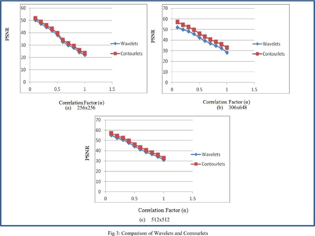
We have compared the performance for image size 306x648 using both transforms. It also concludes that contourlet performs well than wavelet transform if we execute both algorithms on same image of same size. Figure 3(b) illustrates the performance evaluation for both transforms for image size 306x648. In Figure 3(c), the 512x512 image size has been taken. If image size is same for each algorithm, the performance of contourlet transform performs well, and then by increasing image size for both algorithms will not affect the performance of contourlets.
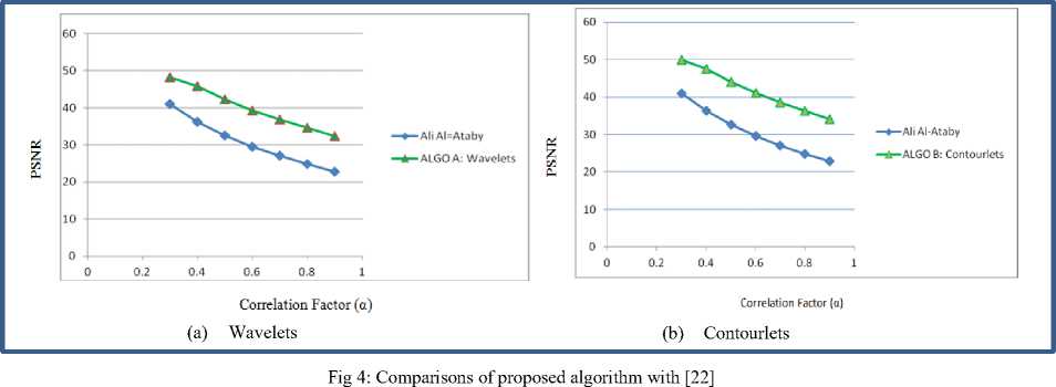
The results of Ali Al-Taby’s work [22] have been compared with the proposed algorithm with both the transforms. Figure 4(a) illustrates the clear increase of PSNR values with respect to the correlation factor for wavelet comparison. Figure 4(b) gives a clear picture of the old results reported by Ali Al-Taby[22] with contourlets. In this the contourlet transform results have been compared. As we already concluded that contourlets gives us better PSNR values in comparison with wavelets. It is very obvious that contourlets performs better than Ali Al-Taby’s work where wavelets were used.
-
V. Conclusions
The proposed systems have been compared with other researcher’s work and proved that the proposed system are improved in terms of PSNR values and image imperceptibility. Moreover, there is a very limited work done in wavelet and contourlet transform domain for colored image steganography. It has also been discussed that the proposed systems inherently preserves the image quality and operates well above on PSNR scale in all the experiments performed. Currently, only one page information of .doc/.docx file is being used. However, the algorithms can be modified to use more number of pages or more number of characters. Texture images can be used for contourlets to have better image quality. As texture images have many edges and contours, appropriate methodologies and experiments can provide better results while using texture images.
Список литературы Efficient Image Steganogrphic Algorithms Utilizing Transforms: Wavelet and Contourlet with Blowfish Encryption
- Aamer Nadeem et al, "A Performance Comparison of Data Encryption Algorithms", IEEE 2005.
- National Institute of Standards and Technology, "Data Encryption Standard (DES)", FIPS PUB 46-3, 1999 October 25.
- NIST, "Report on the Development of the Advanced Encryption Standard (AES)", October 2, 2000.
- David A. Huffman, "A Method for the Construction of Minimum - Redundancy Codes", Proceedings of the I.R.E., September 1952, pp 1098–1102.
- M. Kharrazi, H. T. Sencar, N. Memon, Image Steganography: Concepts and Practice, Lecture Note Series, Institute for Mathematical sciences, National University of Singapore, 2004.
- W. Pennebaker and J. Mitchell. "JPEG STILL IMAGE DATA COMPRESSION STANDARD". van Nostrand Reinhold, 1993.
- L. Marvel "Image Steganography for Hidden Communication". Ph.D. Dissertation, Univ. of Delaware, Dept of EE, 1999.
- Robert T. McKeon "Strange Fourier Steganography in Movies", Proceedings of IEEE EIT 2007.
- R. Gonzalez and R. Woods, "Digital Image Processing", Sec. Edition. pp 373-374.
- S. Mallat, "A theory for multiresolution signal decomposition: the wavelet representation", IEEE Pattern Anal. and Machine Intell., vol. 11, No. 7, pp 674-693, 1989.
- M. Do and M. Vetterli, "The contourlet transform: An efficient directional multiresolution image representation," IEEE Transactions on Image Processing, vol. 14, no. 12, pp. 2091–2106, Dec. 2005.
- M. V. V. Velisavljevic, B. Beferull-Lozano and P. Dragotti, "Directionlets: anisotropic multi-directional representation with separable filtering," IEEE Transactions on Image Processing, vol. 15, no. 7, pp. 1916 – 1933, Jul. 2006.
- E. J. Cand`es and D. L. Donoho, "Curvelets-a surprisingly effective nonadaptive representation for objects with edges," Curve and Surface Fitting, 1999.
- E. L. Pennec and S. Mallat, "Sparse geometric image representation with bandelets," IEEE Transactions on Image Processing, vol. 14, no. 4, pp. 423–438, Apr. 2005.
- Amitava Nag, Sushanta Biswas, Debasree Sarkar & Partha Pratim Sarkar, "A Novel Technique for Image Steganography Based on DWT and Huffman Encoding", International Journal of Computer Science and Security, (IJCSS), Volume (4): Issue (6).
- M. F. Tolba, M. A. Ghonemy, I. A. Taha, and A. S. Khalifa, "USING INTEGER WAVELET TRANSFORMS IN COLORED IMAGE-STEGANOGRAPHY", IJICIS Vol. 4 No. 2, July 200.
- Bo Yang and Beixing Deng, "Steganography in Gray Images Using Wavelet" ISCCSP 2006.
- S.Mallat and F.Falzon, "Analysis of low bit rate image transform coding," IEEE Transactions on Signal Processing, vol. 46, no. 4, pp. 1027–1042, Apr. 1998.
- P. J. Burt and E. H. Adelson, "The laplacian pyramid as a compact image code," IEEE Transactions on Communications, vol. 31, pp. 532–540, Apr. 1983.
- Hedieh SAJEDI, Mansour JAMZAD, "ContSteg: Contourlet-Based Steganography Method", Wireless Sensor Network, 2009, 3, 163-17.
- M. N. Do, "Contourlets and sparse image expansions," Ph.D. dissertation, Department of Electrical and Computer Engineering University of Illinois, Urbana IL, 2003.
- Ali Al-Ataby1 and Fawzi Al-Naima2, "A Modified High Capacity Image Steganography Technique Based on Wavelet Transform", The International Arab Journal of Information Technology, Vol. 7, No. 4, October 2010.
- Hedieh Sajedi Mansour Jamzad, Using contourlet transform and cover selection for secure steganography Published online: 5 August 2010 © Springer-Verlag 2010.
