Efficient Traffic Engineering Strategies for Optimizing Network Throughput in WDM All-Optical Networks

Author: Mohamed Koubàa, Naama Amdouni, Taoufik Aguili
Journal: International Journal of Computer Network and Information Security(IJCNIS) @ijcnis
Article in issue: 6 vol.7, 2015.
Free access
In this paper we investigate traffic-engineering issues in Wavelength Division Multiplexing (WDM) all-optical networks. In such networks, the wavelength continuity constraint along with the wavelength clash constraint, lead to poor network performances when dealing with the lightpath provisioning problem. The impact of these constraints is especially severe when traffic demands are unpredictable and characterized by random arrivals and departures. In order to alleviate the impact of these constraints, we propose to employ intentional/active rerouting. Active lightpath rerouting is to intentionally reroute already established lightpaths, during their life period, so as to achieve a better blocking performance. We here assume that due to the large geographic area an optical WDM network can cover, upgrading such a network to support the huge demand for network bandwidth can be costly. Thereby, it is extremely important for network operators to apply traffic-engineering strategies to cost-effectively optimize network throughput. Two new routing and wavelength assignment (RWA) algorithms applying intentional rerouting are proposed. Both algorithms dynamically reroute some already established lightpaths from longer paths to vacant shorter ones so as to reduce the network resources consumption and hence improve the network throughput. The first algorithm, namely, Timer-Based Active Lightpath Rerouting (TB-ALR) initiates the rerouting procedure every time a timer expires. The second algorithm, namely, Sequential Routing with Active Lightpath Rerouting (SeqRwALR) initiates the rerouting procedure when a connection leaves and its lightpaths are released. To the best of our knowledge, our global approach has not already been investigated in the literature. Simulation results show that the proposed active rerouting algorithms yield much lower connection rejection ratios than rerouting algorithms previously presented in the literature while rerouting a small number of already established lightpaths. By rerouting a small number of existing lightpaths, we hope that the disruption period incurred due to rerouting is minimized.
All-optical WDM networks, Routing and Wavelength Assignment (RWA), Wavelength Continuity Constraint, Traffic Engineering, Intentional/Active Lightpath ReRouting, Network Throughput Optimization
Short address: https://sciup.org/15011419
IDR: 15011419
Text of the scientific article Efficient Traffic Engineering Strategies for Optimizing Network Throughput in WDM All-Optical Networks
Published Online May 2015 in MECS
Wavelength division multiplexing (WDM) optical networks are widely regarded as the best choice for providing the huge bandwidth necessary for emerging applications [1]. In a WDM network, an optical communication path, referred to as lightpath, is set up between a source node and a destination node upon the arrival of a new connection request from the clients [2]. The problem of establishing lightpaths with the objective of optimizing the utilization of network resources is known as the Routing and Wavelength Assignment (RWA) problem also called the Lightpath Provisioning problem [3]. Many studies have been carried out to investigate the RWA problem. Most of the literature on the RWA problem considers either networks with wavelength conversion capabilities [4, 5, 6, 7, 8, 9] or networks without any wavelength conversion [10, 11, 12, 13, 14, 15, 16, 17].
In the absence of wavelength converters, optical networks are referred to as all-optical networks or transparent networks [18, 19]. In such networks, a lightpath connecting the source node to the destination node of a connection request and spanning a set of network fiber-links is established subject to the following two constraints:
-
• Wavelength clash constraint: The wavelength clash constraint states that a wavelength may be used only once per fiber at a given instant.
-
• Wavelength continuity constraint: A lightpath must be assigned the same wavelength along the route (path) it uses from its source node to its destination node 2.
The wavelength continuity constraint leads to inefficient utilization of wavelength channels and results in higher rejection ratio because a non wavelength-continuous route cannot be used to set up a connection request although the route is available. This is especially severe in a circuit-switched network with random circuit arrivals and departures because the unpredictable traffic demand renders the use of routing to mitigate the wavelength continuity constraint ineffective [20]. Wavelength conversion and traffic rerouting are the two possible mechanisms that can increase the efficiency. Wavelength conversion at each node allows the network manager to get rid of the wavelength continuity constraint and hence allows the network to support a larger set of lightpaths. However, such converters remain too expensive and should increase significantly the network capital expenditure [21]. Since, in the foreseeable future, wavelength conversion is expected to remain an expensive technology, traffic rerouting becomes an attractive alternative solution to improve the network throughput conditioned by the aforementioned constraints.
In this paper we present new routing and wavelength assignment algorithms for WDM all-optical networks. We expect to compensate the absence of wavelength converters by the use of efficient rerouting schemes in order to minimize the number of blocked requests for a given number of wavelengths available per each fiberlink in the network when dynamic lightpath demands, referred to as Random Lightpath Demands (RLDs), are considered.
The remainder of this paper is organized as follows. Section II gives the principles of rerouting. Previous work on rerouting is reviewed in Section III. In Section IV, we summarize our main contributions. Section V defines the notations used in subsequent sections. The two proposed intentional lightpath rerouting strategies are presented in details in Section VI. Our simulation results and analysis are given in Section VII. Section VIII concludes the paper.
-
II. Rerouting
The concept of rerouting is originally introduced in the design of circuit-switched telephone networks [22, 23]. It has also been applied to WDM optical networks over the two past decades [20, 24, 25, 26, 27, 28, 29]. Rerouting is defined as the action of switching an already established circuit (or virtual path in ATM networks, lightpath in WDM networks) from one path to another path without changing the source and destination nodes. There are two ways to rearrange an existing lightpath [30]. One is partially rearranging, which keeps the original path of the lightpath to be rerouted but reassigns a different wavelength to the fiber-links along the path. This is also referred to as Wavelength ReRouting (WRR). Another is fully rearranging, which consists of finding a new path with possibly another wavelength to replace the old path. This latter one is referred to as Lightpath ReRouting (LRR). A comprehensive survey of rerouting techniques can be found in [31]. Rerouting in a WDM network can be classified into two categories with respect to the time at which the rerouting procedure is launched. The first is passive rerouting which only performs the rerouting procedure when an incoming lightpath request is to be blocked. The second category is active rerouting which reroutes dynamically existing lightpaths to more suitable physical paths, without affecting other active lightpaths, at some predefined time instants or at periodic intervals according to some predefined criteria. One example is to reroute an existing lightpath from a longer path to a shorter one, another example is to reroute an existing lightpath from an over-loaded path to a slightly-loaded path so as to achieve a better blocking performance. Since the active rerouting is able to adapt the traffic patterns not only when the normal connection set-up procedure fails, we focus on active lightpath rerouting in the rest of the paper.
Let us consider the graph of Fig. 1 representing a network topology with 6 nodes and 12 bidirectional fiberlinks with р/= 2 available wavelengths on each fiber-link. In order to illustrate the principles of passive/active rerouting, we here assume that 5 RLDs are already serviced according to the details given in Table 1. A RLD numbered i , and denoted Tt , is defined by a 5-tuple ( S[ , di , H[ , at , Pi ) where S[ , d[ are the source and the destination nodes of the demand, H[ is the number of requested lightpaths to be set up between St and d[ , and CC[ and Pi are respectively the set-up and tear-down dates of the demand. For the sake of simplicity, we here assume that, for each RLD, only one lightpath is required between the source and the destination nodes of the request ( Hi =1). This scheme can be generalized to consider traffic requests with a required number of lightpaths Hi ( Hi >1) by considering Hi simultaneous traffic requests between the same source and destination nodes with one required lightpath each.
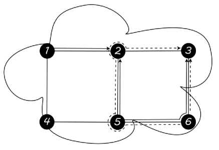
Fig. 1. The RWA of the already serviced RLDs given in Table 1.
Table 1. The set of already serviced RLDs
|
No. |
s |
d |
a |
p |
Physical path |
Wavelength |
|
1 |
1 |
2 |
190 |
520 |
1-2 |
λ 1 |
|
2 |
5 |
3 |
220 |
540 |
5-6-3 |
λ 1 |
|
3 |
6 |
3 |
300 |
450 |
6-3 |
λ 2 |
|
4 |
5 |
2 |
320 |
500 |
5-2 |
λ 1 |
|
5 |
6 |
3 |
350 |
640 |
6-5-2-3 |
λ 2 |
Table 2. The set of RLDs to be set up
|
No. |
s |
d |
α |
β |
|
6 |
4 |
3 |
420 |
820 |
|
7 |
5 |
6 |
425 |
840 |
|
8 |
5 |
2 |
480 |
610 |
Fig. 1 shows the set of already set up lightpaths. Note that lightpaths using wavelength ^1 are drawn using solid lines whereas lightpaths using ^2 are drawn in dashed lines. Now we assume that a new RLD, Г6 , is to be set up between nodes 4 and 3 at time 420 as shown in Table 2. One may notice that no path-free wavelengths are anymore available on any shortest path joining the source node to the destination node of the arriving RLD. We call a path-free wavelength, a wavelength which is not used by any lightpath on any fiber-link of the considered path. Nonetheless, the arriving RLD could be set up once passive rerouting is launched to free a wavelength along one of the shortest paths associated to the RLD. Indeed, assume that RLD T\ is rerouted on the same path 1-2 using wavelength ^2 . Thus, wavelength ^1 is freed along the shortest path 4-1-2-3 and hence may be used to set up the incoming RLD (see Fig. 2).
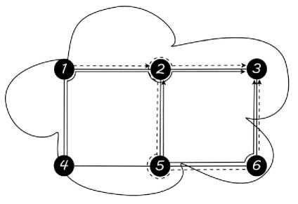
Fig. 2. The RWA of RLD r 6 once passive rerouting is executed
At time t=425, a new RLD is to be set up between nodes 5 and 6. Wavelength Лд is still available along the path 5-6 and is hence used to service the arriving RLD.
Let now assume that a new lightpath is to be set up between nodes 5 and 2 at time t=480. Once again, we notice that no path-free wavelengths are still available along the shortest paths associated to the incoming RLD. RLD 7g is then to be rejected due to lack of resources. Once again, rerouting is launched to free a path-free wavelength in order to set up the lightpath request. Indeed, at time t=450, the lightpath along the physical path 6-3 is released and wavelength ^2 is now available along the path 6-3. Assuming that active rerouting is launched at the departure time of RLD 7*g , RLD r5 is hence rerouted from path 6-5-2-3 on wavelength ^2 to the shorter path 6-3 on the same wavelength. Thus, wavelength ^2 can now be used on the physical path 5-2 to set up RLD 7*g .
-
III. Related Work
Many studies have investigated the problem of rerouting in WDM all-optical networks for dynamic provisioning of lightpath demands. Rerouting may be a viable and cost effective solution to alleviate the impact of the wavelength continuity constraint and hence improve the network throughput by reducing the number of rejected lightpath demands. In [20] and [24], Lee et al. first introduced the wavelength rerouting concept by proposing a wavelength rerouting scheme called Move To Vacant Wavelength Retuning (MTV-WR). The basic idea of this algorithm is that, in case a connection request gets blocked with normal assignment process, a few established lightpaths may be reassigned, if possible, to other wavelengths to enable the new request to get a wavelength-continuous route from its source to destination. While reassigning an existing lightpath, it maintains the original path of the lightpath. In order to shorten the disruption period incurred due to rerouting, the authors proposed the Parallel MTV-WR rerouting scheme allowing the rerouting of multiple lightpaths at the same time. The parallel MTV-WR has the following attractive features. First, it has simple switching control because the old and new paths of rerouted lightpaths share the same switching nodes. Second, it provides shorter disruption period that should be only of the order of microseconds [20]. A time optimal wavelength rerouting algorithm based on the Parallel MTV-WR rerouting scheme was presented later in [25].
In [32] and [33], Wason et al. proposed two low complexity wavelength rerouting algorithms to improve throughput and to reduce blocking probability in wavelength division multiplexed networks. The former is called the Shortest Path Wavelength ReRouting (SPWRR) algorithm while the latter is called the Lightpath ReRouting Algorithm (LRRA). Wason et al. also demonstrated that LRRA gives better results and can be implemented to huge networks for good blocking performance.
While in all of the above described algorithms dynamic traffic is considered, in [21], Koubàa et al. proposed a new lightpath rerouting scheme to optimize network resources allocation considering three types of traffic demands namely Permanent Lightpath Demands (PLDs), Scheduled Lightpath Demands (SLDs), and Random Lightpath Demands (RLDs).
Recently, a new lightpath rerouting scheme called Sequential Routing with Lightpath Rerouting (SeqRwLR) is proposed in [34] to improve the rejection ratio while keeping a small service disruption time.
All of the aforementioned rerouting algorithms used the passive rerouting concept i.e. they only perform rerouting when a new connection request is to be blocked. In [26], Chu et al. proposed a Dynamic Least Congested Routing (DLCR) algorithm, which dynamically switches the lightpath between the primary route and alternate route according to the network traffic distribution. The authors also demonstrated that the performance gain is more significant when wavelength conversion is available.
In [35] and [36], Ho et al. developed a rerouting approach which actively packs existing connections of different bandwidth granularities. Basically different from previously proposed active rerouting that blindly attempts to reroute many existing lightpaths, the proposed algorithm at first estimates the potential resource gain of each existing connection and then reroutes only a small number of candidate connections that may give the largest gain. The objective is to maximize the amount of resources that can be conserved for future requests and hence improve the network throughput.
In [37] and [38], Chu et al. investigated passive rerouting, intentional rerouting and hybrid rerouting which combines passive and intentional rerouting. The authors showed that when there is wavelength conversion, passive rerouting works much better than intentional rerouting, and hybrid rerouting can only improve the performance over passive rerouting slightly. In the absence of wavelength converters, the authors demonstrated that WRR achieve the most benefit of passive rerouting, whereas path adjusting does not help any further. The authors also showed that hybrid rerouting can improve the blocking performance significantly.
-
IV. Contribution of the Paper
In this paper we propose two RWA algorithms applying active lightpath rerouting for WDM all-optical networks without wavelength conversion. These two algorithms are referred to as the Timer-Based Active Lightpath Rerouting algorithm (TB-ALR) and the Sequential Routing with Active Lightpath Rerouting algorithm (SeqRwALR) respectively. The connection requests, referred to as Random Lightpath Demands (RLDs), are assumed to be with random arrivals and departures. The basic idea of both algorithms is to dynamically reroute some already established lightpaths to more appropriate physical paths so as to reduce the network resources consumption. This should hopefully give better performances in terms of rejection ratio. The TB-ALR algorithm initiates the rerouting procedure at some predefined time instants whereas the SeqRwALR algorithm initiates the rerouting procedure at the end time of an established connection request when its lightpath is released.
Our simulation results show that, in the absence of wavelength converters and in contrast to the results announced in [37], the two proposed active rerouting algorithms provide better blocking performances than previously presented passive rerouting algorithms.
-
V. Notations
We use the following notations and typographical conventions:
-
• G=(V,E,η) is an arc-weighted symmetrical
directed graph representing the network topology with vertex set , arc set and weight function л: →ℝ+ mapping the physical length or any other cost of the links set by the network operator of each arc of . The weight function may incorporate dynamic network status information such as congestion, capacity, and reliability. We here assume that all fiber-links have the same cost equal to 1.
-
• N =| V | denotes the number of vertices (network nodes) of the directed graph representing the network topology.
-
• L =| E | denotes the number of arcs (network links) of the directed graph representing the network topology.
-
• Л ={ ^-i ,A 2,․․․, ^-W } is the set of available
wavelengths on each fiber-link of the network.
-
• w =| Л | denotes the number of available
wavelengths (i.e., optical channels) per fiber-link. We assume that all the network links have the same number of available wavelengths.
-
• D denotes the total number of RLDs to be set up.
-
• Pi ,1 ≤ i ≤ D , represents the shortest path in already used by ri.
-
• M-i ,1 ≤ I ≤ D , is a positive number corresponding to the number of hops on P .
-
• Ri ,1 ≤ I ≤ D , represents the shortest path in on which r। is to be rerouted.
-
• ^i ,1 ≤ I ≤ D , is a positive number corresponding to the number of hops on R( .
-
VI. The Proposed Algorithms
When an arriving RLD is to be set up, it may happen that no more path-free wavelengths are available on the shortest path associated to the RLD. Moreover, the RLD may be serviced on a physical path much longer than the shortest path. This may lead to a higher consumption of network resources and a reduction of the overall resource utilization efficiency. For this purpose, we here propose, as mentioned in the preceding sections, two rerouting algorithms to improve the network blocking performance in WDM all-optical networks.
The main difference between the two proposed algorithms concerns the time at which rerouting is launched. The TB-ALR algorithm initiates the rerouting procedure multiple times during the life period of a RLD. Indeed, a timer is cocked at the setup time of the arriving RLD and the rerouting procedure is launched whenever the timer expires. Once the rerouting procedure is executed, the timer is cocked once again. Unlike the TB-ALR algorithm, the SeqRwALR algorithm launches the rerouting procedure when an established connection leaves the network. Both algorithms use the same routing procedure. In the following, the routing and rerouting procedures are explained in details.
-
A. The routing procedure
Both algorithms compute the RWA for the RLDs sequentially, that is demand by demand at the arrival date of each RLD using the algorithm described in [24]. The approach is to transform the network to a graph. The graph’s vertices correspond to the network nodes whereas the edges correspond to the fiber-links. Each edge in the graph is associated a weight label representing the cost of routing a new lightpath on the corresponding fiber-link.
To reduce the computational complexity and to simplify the notation, we decompose the graph into a few disjoint subgraphs, each corresponding to the network on a particular wavelength. The routing algorithm finds the shortest path on each subgraph and then chooses the least costly one among all the individual subgraphs. Smallest wavelength index is used to break a tie. The minimumcost wavelength and its associated shortest path, if the routing of the demand is feasible, are selected according to the following three steps:
Step 1: Graph Transformation
The network G = ( V, E) with the wavelength set / is transformed into a collection of disjoint subgraphs G (V я , Е я ), AG/, each corresponding to the network on a particular wavelength. For each wavelength AG /, the subgraph G (V я , Е я ) is obtained by generating a vertex I я and an edge (I я , ;я) if i G V and( i, j ) G E, respectively. Thus the new graph is и^ед G (V я , Е я ) where:
V я ={ I я : i G V },AG?1 (1)
Е я = {( ^,;я ): (i, j )G E }, AG/ (2)
Step 2: Cost Labelling c (Iя, jя) is the cost of using wavelength A on link ( , ). The weight function of each edge of the graph is determined by whether a channel is free or busy, i.e.,
(i Я , Iя) = {
, ( , )
+“, otherwise
where is a tiny positive value.
Step 3: Route Searching
For each AG/ , the routing algorithm computes the shortest loop-free path with finite cost on each subgraph G (V я , Е я ) according to the algorithm described in [39]. Let 22 be the set of all computed shortest paths. Two cases may happen:
-
• 22 = 0, no shortest paths with finite cost exist and
the arriving RLD is hence rejected.
-
• 22 ^ 0, which means that there is at least one
available path-free wavelength along one shortest path connecting the source node to the destination node of the RLD to be set up. The least costly path and its corresponding wavelength are selected to break a tie. It may happen that two or multiple shortest paths have the same cost. In that case, the wavelength with the smallest index is used.
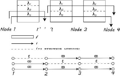
О A network node on a wavelength — An occupied channel edge
--- An available channel edge
Fig. 3. Illustration of the graph transformation and the cost labelling of routing procedure
Mode 2
A fiber-link with Ж A traffic connection An available channel
Fig. 3 shows an illustration of decomposing the network into wavelength-disjoint subgraphs and the cost labeling. For the sake of simplicity, we considered a network topology with 4 network nodes. A fiber-link connects each pair of nodes. We assume that there are 3 available wavelengths on each fiber-link. Three lightpaths are already set up according to the details given on Fig. 3. The network topology is transformed into 3 wavelength-disjoint subgraphs. A channel edge is created to represent a channel with the cost of if the channel is idle and infinity if the channel is occupied.
-
B. The rerouting procedure
In the following we describe the rerouting procedure for the TB-ALR algorithm and the SeqRwALR algorithm.
Timer-Based Active Lightpath Rerouting algorithm’s rerouting procedure
When a new arriving RLD r , is to be set up on path Pt , a rerouting timer is started. This timer starts at a predetermined value (denoted ) and counts down over time. When the rerouting timer expires, the rerouting procedure is launched. The rerouting procedure aims at rerouting the RLD to a vacant shorter path using the three steps of the routing procedure described in Subsection VI.A. Two different situations may happen:
-
• / , — v , > о i.e. the difference between the number of
hops of and that of the new vacant path is higher than the pre-defined rerouting threshold o. The new path is considered to be more suitable to carry the traffic of the active RLD. is hence rerouted from to R , . The cost of the edges on R , is updated to +^ and that of the edges on the released path is updated to .
-
• If / , — v , < o. We here assume that it is not worthy
to reroute the active RLD to and no rerouting is performed. is still used to carry the traffic of .
At the end of the rerouting procedure, the timer is reinitialized to к and the rerouting procedure is once again launched when the timer expires. The same process is reiterated until the departure time of the RLD. The optimal value of the rerouting timer, к , is to be discussed in the simulation results section.
In order to illustrate the principles of the TB-ALR algorithm, we consider once again the example given in Section II. We also assume that the value of the threshold <т is set to 2 and that of the rerouting timer к is set to 50. We still assume that seven RLDs are already routed according to the details given in Table 3 and that a new RLD is to be set up at time 480 between nodes 5 and 2. One may notice that at the arrival date of the new RLD, ^-1 and Л 2 are already used by the serviced RLDs on the shortest paths joining the source node 5 to the destination node 2. The routing procedure fails to compute a path-free wavelength for the new RLD if rerouting is not allowed. The RLD is then to be blocked due to lack of resources.
Table 3. The set of already serviced RLDs
|
No. |
s |
d |
а |
р |
Physical path |
Wavelength |
|
1 |
1 |
2 |
190 |
520 |
1-2 |
λ 2 |
|
2 |
5 |
3 |
220 |
540 |
5-6-3 |
λ 1 |
|
3 |
6 |
3 |
300 |
450 |
6-3 |
λ 2 |
|
4 |
5 |
2 |
320 |
500 |
5-2 |
λ 1 |
|
5 |
6 |
3 |
350 |
640 |
6-5-2-3 |
λ 2 |
|
6 |
4 |
3 |
420 |
820 |
4-1-2-3 |
λ 1 |
|
7 |
5 |
6 |
425 |
840 |
5-6 |
λ 2 |
Assuming that active rerouting is launched every time a timer associated to an established RLD expires, the rerouting procedure of the TB-ALR algorithm tries to reroute Г5 for the first time at t=400 when the first timer associated to the RLD, started at t=350, expires. The rerouting procedure fails in rerouting Г5 as both wavelengths are already used on the shortest paths corresponding to the RLD. The rerouting timer К is hence reinitialized to 50 and the rerouting procedure is to be launched again when the timer expires at time t=450. One should notice here that at time t=450, the lightpath of RLD Г3 is released and hence Г5 can be rerouted to path 6-3 on wavelength Л 2 as М-5 - Vg ≥ а =2. Therefore the new RLD can be set up at time t=480 using wavelength Л 2 on the physical path 5-2.
Sequential Routing with Active Lightpath Rerouting algorithm’s rerouting procedure
The rerouting procedure is launched at the departure time of a RLD when the corresponding WDM channels are released. We first compute Ф( , the set of existing RLDs that should be rerouted when a RLD Г( leaves the network at time t. The RLDs to be rerouted must meet simultaneously the following two constraints:
Once ф[ is computed, two cases may happen:
-
• ф[ =∅ . None of the existing RLDs satisfy the preceding constraints. No rerouting is to be executed.
-
• ф[ ≠∅ . Each RLD in ф[ is hence rerouted to a vacant shorter path using the routing procedure described in Subsection VI.A. The costs of the new path’s edges used by the rerouted RLD are updated to +∞ and to £ the costs of the released path’s edges.
In order to illustrate the principles of the SeqRwALR algorithm, let us consider once again the example given in the preceding section. We still assume that 7 RLDs are already routed according to the details given in Table 3 and that a new RLD is to be set up at time 480 between nodes 5 and 2. The routing algorithm fails to compute a path-free wavelength for the incoming RLD. The RLD is hence rejected at the end of the routing phase.
The SeqRwALR’s rerouting procedure is executed for the first time at the departure time of RLD 7*2 (t=450). Фз50 ≠∅ asг5 can be rerouted from the physical path 6-5-2-3 on wavelength ^-2 to the physical path 6-3 using wavelength ^-1 which become available once the lightpath associated to 7*2 is released. We here assume once again that the rerouting threshold is set to 2. Thus, the new RLD arriving at the network at time t=480 and to be set up between the source node 5 and the destination node 2 is serviced on the physical path 5-2 using wavelength ^2 .
-
VII. Simulation Results
In this section, we experimentally evaluate and compare the performance of the two proposed algorithms presented in Section VI. We used the network topologies shown in Fig. 4 and 5 with 21 and 29 nodes, respectively. The source and destination nodes of the RLDs are drawn according to a random uniform distribution in the interval [1, 21] for the 21-node network and in [1,29] for the 29-node network. We assume that the RLDs arrive at the network randomly according to a Poisson process with common arrival rate per node Г and once accepted, will hold the circuits for exponentially distributed times with mean holding time equal to 1 time unit much larger than the network-wide propagation delay and the connection set-up delay. We also assume that there are р/ =13 wavelengths on each fiber-link in the network. Each node has enough transmitters and receivers such that a new RLD will not be blocked due to lack of transmitters and receivers. A blocked RLD is cleared and will not retry.
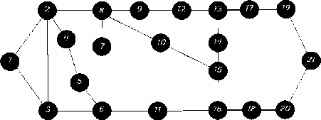
Fig. 4. The 21-node network topology
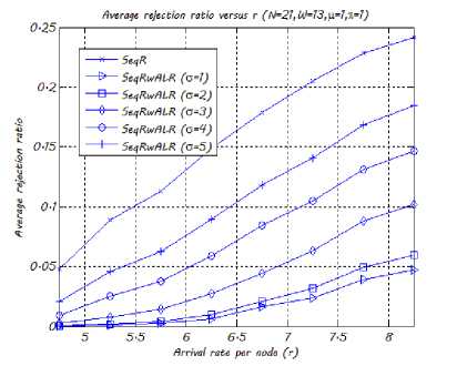
Fig. 6. The SeqRwALR algorithm’s average rejection ratio w.r.t. r
We generate 25 test scenarios, run the algorithms for each scenario, and compute rejection ratio averages, rejection ratio gain averages and average ratios of rerouted connection for each algorithm. Since the curves obtained for the 29-node network have the same shapes as those obtained for the 21-node network, we here propose to only report the curves obtained for the 21-node network topology.
In the following, we propose to compare the performances of the TB-ALR algorithm with respect to the SeqRwALR algorithm. In order to assess the gain obtained thanks to rerouting, we also propose to compare the performance of both algorithms to that of a traditional no-rerouting algorithm called the sequential RWA algorithm (SeqR) which computes the RWA for the RLDs on the fly without any rerouting according to the routing procedure described in Subsection VI.A.
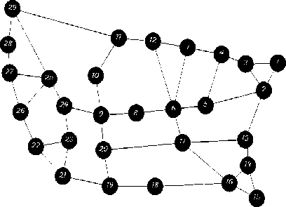
Fig. 5. The 29-node network topology
Fig. 6 shows the impact of the rerouting threshold σ on the SeqRwALR algorithm’s rejection ratio. The results confirm the intuition that the smaller the value of σ is, the lower the rejection ratio is. Indeed, when the value of σ decreases, the number of RLDs to be rerouted is increased resulting in lower rejection ratios but higher service disruption periods. One should here emphasises once again the trade-off between the number of RLDs to be rerouted and the overall disruption period incurred due to rerouting. Fig. 6 also shows the impact of rerouting on the overall rejection ratio as we plot on the same figure the performance of the SeqR algorithm.
Fig. 7 shows the impact of σ on the SeqRwALR algorithm’s average ratio of rerouted RLDs and average rejection ratio gain. The average rejection ratio gain is computed as the difference between the average number of rejected RLDs computed by the SeqR and the SeqRwALR algorithms respectively, divided by the total number of RLDs arriving at the network and multiplied by 100. The average ratio of rerouted RLDs has been computed as the average number of rerouted RLDs divided by the total number of RLDs arriving at the network and multiplied by 100. From this figure, we notice that when а increases, the average ratio of rerouted RLDs and the rejection ratio gain decrease. In fact, when <т increases, fewer RLDs are to be rerouted (only those having a difference between the number of hops on their paths and that of the new vacant paths on which the RLD are to be rerouted greater than the rerouting threshold а ). On the one hand, this should lead to short service disruption period, but on the other hand, it becomes increasingly difficult to reduce the network wavelength resources consumption. This explains why the rejection ratio gain falls down when а increases. We also observe that a rerouting threshold а equal to 3 provides a good trade-off since for such value our scheme provides an average rejection ratio gain of 11.33% (respectively 11.39% for the 29-node network) and reroutes on the average 24% of existing RLDs (respectively 29% for the 29-node network).
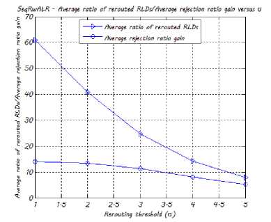
Fig. 7. The SeqRwALR algorithm’s average ratio of rerouted RLDs /average rejection ratio gain w.r.t. σ
In Fig. 8 we draw the impact of the rerouting timer’s predetermined value к on the TB-ALR algorithm’s rejection ratio. We notice that small values of к give better performances in terms of rejection ratio. But with the decrease of к , the signaling overhead will increase because the TB-ALR algorithm needs to refresh the information of network status more frequently. In order to highlight the gain obtained due to rerouting, we also plot on the same figure the average rejection ratio obtained by the sequential routing algorithm.
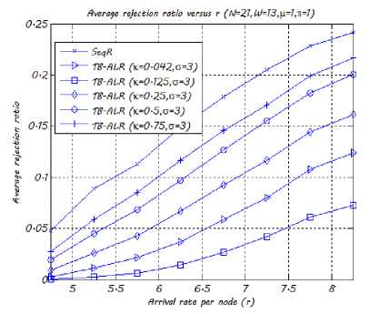
Fig. 8. The TB-ALR algorithm's average rejection ratio w.r.t. r
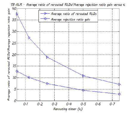
Fig. 9. The TB-ALR algorithm's average ratio of rerouted RLDs /average rejection ratio gain w.r.t. κ
In Fig. 9, we plot the average ratio of rerouted RLDs and the average rejection ratio gain obtained by the TB-ALR algorithm w.r.t. к . One may notice here that the rejection ratio gain and к are inversely proportional. Indeed, when the value of к decreases, the rejection ratio gain increases. An average rejection ratio gain of 12.8% (respectively 12.3% for the 29-node network) is observed for к = 0.042 under the aforementioned simulation parameters. The average rejection ratio gain is equal to 2.9% (respectively 3.3% for the 29-node network) when the value of к is equal to 0.75. This result is quite trivial because when the value of the rerouting timer к decreases, the rerouting procedure is launched multiple times and thereby a lot of existing RLDs are rerouted leading to lower resources consumption and hence higher rejection ratio gain. This gain goes along with an increase in the number of RLDs to be rerouted and thus an increase of the signaling overhead and the service disruption period as illustrated in Fig. 9.
A new trade-off arises between the rejection ratio gain and the rerouting timer к , from the preceding observations. A reasonable trade-off is observed for =
0.125 as the average rejection ratio gain is equal to 10.11% (respectively 10.43% for the 29-node network) while the signaling overhead and the service disruption period are still acceptable since the average ratio of rerouted RLDs is 27.3% (respectively 30.4% for the 29-node network). For instance, if the average lightpath holding time is one day, then к can be set to 3 hours to achieve good performance while keeping the overhead and the service disruption period at a very low level.
In order to validate the choice of the value of the rerouting threshold а , we plot in Fig. 10 the average ratio of rerouted RLDs and the average rejection ratio computed by the TB-ALR algorithm w.r.t. а for = 0.125. One may notice that for а = 1 and а = 2 a large number of RLDs are rerouted (78% and 47% respectively) for a slight rejection ratio gain compared to а = 3. We therefore set, in the following, the value of а to 3 and that of к to 0.125 and propose to study the performances of our two intentional lightpath rerouting schemes, in comparison with those obtained by the SeqR algorithm and the following two algorithms:
-
• The Sequential Routing with Lightpath Rerouting algorithm (SeqRwLR) described in [34]. The SeqRwLR algorithm is a passive lightpath rerouting algorithm, which initiates the rerouting procedure at the set-up time of an arriving RLD to be blocked due to lack of resources.
-
• The Parallel Move To Vacant Wavelength Retuning algorithm (Parallel MTV-WR) described in [20]. The Parallel MTV-WR algorithm is a passive wavelength rerouting algorithm that performs wavelength rerouting at the set-up time of an arriving RLD to be rejected due to lack of resources.
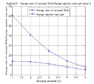
Fig. 10. The TB-ALR algorithm's average ratio of rerouted RLDs /average rejection ratio gain w.r.t. σ for κ = 0.125
Fig. 11 shows the average lightpath demand rejection ratio computed by the above five algorithms with respect to traffic loading per node, г . From this Figure, one may bring out the following four main conclusions.
-
• Thanks to rerouting (be it active or passive), the RLD rejection ratio is improved. On the average, the rejection ratio is reduced up to 2% with the Parallel MTV-WR algorithm, 5% with the SeqRwLR algorithm, 12% with the TB-ALR algorithm and 14% with the SeqRwALR algorithm.
-
• The Parallel MTV-WR algorithm has the worst blocking performance. This is because the Parallel MTV-WR algorithm performs the rerouting using only WRR whereas all the other rerouting algorithms use LRR.
-
• The proposed active rerouting algorithms perform better than the two passive rerouting algorithms. By rerouting the existing RLDs to more suitable physical paths, the WDM channels consumption is minimized allowing the accommodation of a maximum number of incoming requests and leading to better rejection ratios.
-
• Unexpectedly, the performance of the TB-ALR algorithm is not as good as that of the SeqRwALR algorithm despite the fact that the TB-ALR algorithm allows multiple rerouting of an active RLD. On the average, the latter rejects 2% fewer requests than the former. This is mainly due to the rerouting threshold constraint; а ․ Let us remind that an active RLD is rerouted only if the new path, on which the RLD is to be rerouted, is σ hops lower than the number of hops on the physical path already used by the RLD. Because of this constraint, fewer RLDs are rerouted several times during their life period. The impact of this constraint becomes severe when the number of accepted RLDs increases in the network. Moreover, the SeqRwALR algorithm launches the rerouting procedure at the end time of an established RLD when its lightpath is released and hence network resources consumption reduction can be very impressive. On the opposite, the TB-ALR initiates the rerouting procedure at some predefined time instants that do not correspond necessarily to the departure times of already set up RLDs. This causes the failure of the rerouting procedure when no network resources are released.
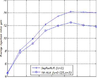
In Fig. 12, we draw the average rejection ratio gain versus г . One may notice that the rejection ratio gain increases with the traffic load before it falls down under heavy traffic load. In fact, under low traffic load, both algorithms still manage to reduce network resources consumption by rerouting some of the existing RLDs on shorter new physical paths and hence set up new arriving requests. As the traffic load increases, it becomes increasingly difficult to find new vacant shorter paths on which the existing RLDs can be rerouted in order to set up more requests. The network reaches its saturation regime. Note that the TB-ALR algorithm achieves a maximum rejection ratio gain equal to 12.46% (respectively 13.46% for the 29-node network) whereas the SeqRwALR achieves a maximum rejection ratio gain equal to 14.17% (respectively 15.63% for the 29-node network) under the aforementioned simulation parameters.
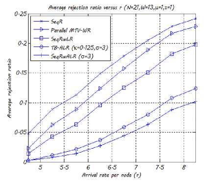
Fig. 11. Average rejection ratio w.r.t. r
Average rejection ratio gain versus r (N=2?, ld=13, Ц=7^
5 5-5 6 6-5 7 7-5 8
Arrival rate per node fr)
Fig. 12. Average rejection ratio gain w.r.t. r
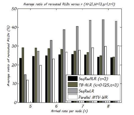
Fig. 13. Average ratio of rerouted RLDs w.r.t. r
In Fig. 13, each group of four bars shows the average ratio of rerouted RLDs computed using the SeqRwALR algorithm (first bar from the left-hand side), the TB-ALR algorithm (second bar), the SeqRwLR algorithm (third bar) and the Parallel MTV-WR algorithm (fourth bar) respectively. From Fig. 13, we notice that for small values of г , active lightpath rerouting algorithms require more active RLDs to be rerouted than passive lightpath rerouting algorithms whereas under high traffic load, active lightpath rerouting algorithms reroute fewer existing RLDs than passive rerouting algorithms. This can be explained by the fact that passive rerouting algorithms require to reroute a large number of existing RLDs under high traffic load when it becomes difficult to set up an arriving RLD without rerouting existing RLDs as the amount of available network resources become very low. Unlike passive rerouting algorithms, the number of RLDs to be rerouted decreases with г for active rerouting algorithms. Indeed, when the network reaches its saturation regime, it becomes difficult to reroute an active lightpath to a more suitable path satisfying the rerouting threshold constraint.
-
VIII. Conclusion
In this paper, we proposed two simple intentional rerouting schemes for WDM all-optical networks under random traffic. Simulation results show that the proposed schemes yield much lower rejection ratios than traditional no-rerouting algorithms. Furthermore, our intentional rerouting algorithms perform better than passive rerouting algorithms previously presented in the literature. The main reason is that intentional rerouting schemes switch dynamically existing lightpaths from longer paths to vacant shorter ones so as to reduce the total number of consumed WDM channels and therefore improve the network throughput. Moreover, the two proposed intentional rerouting algorithms reroute a minimum number of active RLDs. We hope, thus, that our algorithms achieve minimum service disruption periods.
Our forthcoming studies will investigate the RWA problem applying hybrid rerouting in all-optical WDM networks to, hopefully, increase network throughput while shortening the service disruption period and decreasing the signaling overhead.
References Efficient Traffic Engineering Strategies for Optimizing Network Throughput in WDM All-Optical Networks
- N. Zhang and H. Bao, "Re-routing Technology and Its Application in Optical Network," in Proceedings, 2010 International Conference on Innovative Computing and Communication and 2010 Asia-Pacific Conference on Information Technology and Ocean Engineering, pp. 24-27, 2010.
- I. Chlamtac, A. Ganz, and G. Karmi, "Lightpath Communications: An Approach to High-Bandwidth Optical WANs," IEEE Transactions on Communications, 40(7):1171-1182, Jul. 1992.
- H. Zang, J. P. Jue, and B. Mukherjee, "A Review of Routing and Wavelength Assignment Approaches for Wavelength-Routed Optical WDM Networks," Optical Networks Magazine, 1(1):47-60, 2000.
- M. Kovacevic and A. Acampora, "Benefits of Wavelength Translation in All-Optical Clear-channel Networks," IEEE Journal on Selected Areas in Communications, 14(5):868-880, 1996.
- H. Q. Ngo, D. Pan, and Y. Yang, "Optical Switching Networks with Minimum Number of Limited Range Wavelength Converters," in Proceedings, IEEE INFOCOM, volume 2, pp. 1128-1138, 2005.
- B. Ramamurthy and B. Mukherjee, "Wavelength Conversion in WDM Networking," IEEE Journal on Selected Areas in Communications, 16(7):1061-1073, 1998.
- S. Subramaniam, M. Azizoglu, and A. K. Somani, "All-Optical Networks with Sparse Wavelength Conversion," IEEE/ACM Transactions on Networking, 4(4):544-557, 1996.
- J. Yates, J. Lacey, D. Everitt, and M. Summerfield, "Limited Range Wavelength Translation in All-Optical Networks," in Proceedings, IEEE INFOCOM, pp. 954-961, 1996.
- X. Chu and B. Li, "Dynamic Routing and Wavelength Assignment in the Presence of Wavelength Conversion for All-Optical Networks," IEEE/ACM Transactions on Networking, 13(3):704-715, 2005.
- K. Chan and T. P. Yum, "Analysis of Least Congested Path Routing in WDM Lightwaves Networks," in Proceedings, IEEE INFOCOM, pp. 962-969, 1994.
- H. Harai, M. Murata, and H. Miyahara, "Performance of Alternate Routing Methods in All-Optical Switching Networks," in Proceedings, IEEE INFOCOM, pp. 517-525, 1997.
- L. Li and A. K. Somani, "Dynamic Wavelength Routing Using Congestion and Neighbourhood Information," IEEE/ACM Transactions on Networking, 7(5):779-786, 1999.
- A. Mokhtar and M. Azizoglu, "Adaptive Wavelength Routing in All-Optical Networks," IEEE/ACM Transactions on Networking, 6(2):197-206, 1998.
- S. Ramamurthy and B. Mukherjee, "Fixed-Alternate Routing and Wavelength Conversion in Wavelength-Routed Optical Networks," IEEE/ACM Transactions on Networking, 10(3):351-367, 1998.
- R. Ramaswami and K. Sivarajan, "Routing and Wavelength Assignment in All-Optical Networks," IEEE/ACM Transactions on Networking, 3(5):489-500, 1995.
- Y. Zhu, G. N. Rouskas, and H. G. Perros, "A Comparison of Allocation Policies in Wavelength Routing Networks," Photonic Network Communications Journal, 2(3):265-293, 2000.
- M. Koubàa, N. Puech, and M. Gagnaire, "Routing and Wavelength Assignment of Scheduled and Random Lightpath Demands," in Proceedings, IEEE Wireless and Optical Communications Networks, pp. 7-9, 2004.
- A. A. M. Saleh, "Transparent Optical Networking in Backbone Networks," in OFC, pp. 62-64, 2000.
- I. Tomkos, "Transport Performance of WDM Metropolitan Area Transparent Optical Networks," in OFC, pp. 350-352, 2002.
- K. C. Lee and V. O. K. Li, "A Wavelength Rerouting Algorithm in Wide-Area All-Optical Networks," IEEE/OSA Journal of Lightwave Technology, 14(6):1218-1229, 1996.
- M. Koubàa and M. Gagnaire, "Lightpath Rerouting Strategies in WDM All-Optical Networks Under Scheduled and Random Traffic," IEEE/OSA Journal of Optical Communications and Networking, 2(10):859-871, 2010.
- M. H. Ackroyd, "Call Repacking in Connecting Networks," IEEE Transactions on Communications, 27(3):589-591, 1979.
- A. Girard and S. Hurtubise, "Dynamic Routing and Call Repacking in Circuit-Switched Networks," IEEE Transactions on Communications, 31(12):1290-1294, 1983.
- K. C. Lee and V. O. K. Li, "A Circuit Rerouting Algorithm for All-Optical Wide-Area Networks," in Proceedings, IEEE INFOCOM, pp. 954-961, 1994.
- G. Mohan and C. S. R. Murthy, "A Time Optimal Wavelength Rerouting Algorithm for Dynamic Traffic in WDM Networks," IEEE/OSA Journal of Lightwave Technology, 17(3):406-417, 1999.
- X. Chu and J. Liu, "DLCR: A New Adaptive Routing Scheme in WDM Mesh Networks," in Proceedings, IEEE International Conference on Communications, pp. 1797-1801, 2005.
- R. Datta, S. Ghose, and I. Sengupta, "A Rerouting Technique with Minimum Traffic Disruption for Dynamic Traffic in WDM Networks," in Proceedings, IEEE Conference on Networks, pp. 425-430, 2003.
- G. Xue, "Optimal Lightpath Routing and Rerouting in WDM Networks," in Proceedings, IEEE Globecom, pp. 2124-2128, 2001.
- W. Yao and B. Ramamurthy, "Rerouting Schemes for Dynamic Traffic Grooming in Optical WDM Mesh Networks," in Proceedings, IEEE Globecom, pp. 1793-1797, 2004.
- Y. Wan and W. Liang, "Wavelength Rerouting in Survivable WDM Networks," Lecture Notes in Computer Science, 3462:431-442, 2005.
- E. W. M. Wong, A. K. M. Chan, and T. S. P. Yum, "A Taxonomy of Rerouting in Circuit Switched Networks," IEEE Communications Magazine, 37(11):116-122, 1999.
- A. Wason and R.S. Kaler, "Rerouting Technique with Dynamic Traffic in WDM Optical Networks," Optical Fiber Technology, 16(1):950-954, 2010.
- A. Wason and R.S. Kaler, "Lightpath Rerouting Algorithm to Enhance Blocking Performance in All-optical WDM Network without Wavelength Conversion," Optical Fiber Technology, 16(3):146-150, 2010.
- N. Amdouni, M. Koubàa, and T. Aguili, "Lightpath Rerouting Scheme for Dynamic Traffic in WDM All-Optical Networks," in Proceedings, IEEE International Conference on Computer Systems and Industrial Informatics (ICCSII12), pp. 1-6, 2012.
- Q. D. Ho and M. S. Lee, "Connection Level Active Rerouting in WDM Mesh Networks with Traffic Grooming Capability," in Proceedings, IEEE International Conference on Communications, volume 5, pp. 2415-2420, 2006.
- Q. D. Ho and M. S. Lee, "Source-initiated Active Rerouting in WDM Mesh Networks with Traffic Grooming Capability," in Proceedings, The Joint International Conference on Optical Internet and Next Generation Network, pp. 100-104, 2006.
- X. Chu, T. Bu, and X Li, "A Study of Lightpath Rerouting Schemes in Wavelength-Routed WDM Networks," in Proceedings, IEEE International Conference on Communications, pp. 2400-2405, 2007.
- X. Chu, H. Yin, and X. Li, "Lightpath Rerouting in Wavelength-Routed WDM Networks," IEEE/OSA Journal of Optical Communications and Networking, 7(8):721-735, 2008.
- D. Eppstein, "Finding the k Shortest Path," in Proceedings, IEEE Symposium on Foundations of Computer Science, pp. 154-165, 1994.
