Elaboration and testing of the algorithm which ensures an achievement of minimal deviation angle of flying model’s main centroidal axis of inertia during her counterbalancing in a sole correction flatness

Author: Klyuchnikov A. V.
Journal: Siberian Aerospace Journal @vestnik-sibsau-en
Section: Aviation and spacecraft engineering
Article in issue: 1 vol.21, 2020.
Free access
High complexity and cost of developing flying models necessitate the use of such design and production techniques that would ensure the best flight technical and technological characteristics of the model also would raise of it operation effectiveness. These techniques include the experimental control method of flying model’s mass-inertia asymmetry parameters during final assembly of the model. Solution of the problem of optimization the process of bringing parameters of mass-inertia asymmetry of the conical flying model to specified standards is considered in the article. The only correction plane is designed to be positioned close to cone face, away from the center mass of the flying model. The flying model as a component of prefabricated rotor is being balanced in dynamic mode on a low-frequency dynamic vertical stand, which based on gas bearings. Before balancing experiment the weigh, longitudinal center of mass and inertia moments of the flying model have to be controlled with use of another measurement equipment. As a criterion of optimization is sorted the reaching of minimum of the angle of deviation of principal longitudinal centroidal axis of inertia from geometrical axis of the flying model. But simultaneously the pre-set standard of center-mass shift from the geometrical axis must be ensured. Balancing algorithm, easy-to-realized by modern computers, is presented. Numerical illustration of balancing is given. The algorithm enables omitting intermediate steps of balancing, reducing them to one step (as a rule), and shortening the balancing time, as well. In one step of balancing the engineering model permits either bringing parameters of mass-inertia asymmetry of the flying model to specified standards, or diagnosing impossibility of attaining the specified standards with available design of flying model. The algorithm and balancing method are experimentally tested at newly-designed vertical dynamic stand on conical gas bearings. It’s high precision and efficiency are corroborated.
Mass-inertia asymmetry, balancing stand, axis of symmetry, axis of inertia, moment of inertia, correction plane, misbalance, algorithm.
Short address: https://sciup.org/148321722
IDR: 148321722 | UDC: 681.828 | DOI: 10.31772/2587-6066-2020-21-1-70-77
Text of the scientific article Elaboration and testing of the algorithm which ensures an achievement of minimal deviation angle of flying model’s main centroidal axis of inertia during her counterbalancing in a sole correction flatness
Introduction. This article continues the work [1; 2], in which the problem of balancing in the dynamic mode with the minimum displacement of the center of mass from the geometric axis stabilized by rotation of the conical flying model (LM), the cone of which is characterized by a small half-angle of the solution, was considered. Balancing is performed at the final stage of the general assembly of the model. In accordance with the algorithm given in [1], the model is balanced as a part of a prefabricated rotor, on a low-frequency dynamic balancing stand with gas supports and a vertical axis of rotation [3; 4]. The balancing process involves the determination and subsequent reduction of the parameters of mass-inertial asymmetry of the model, which include the value of the transverse displacement of the center of mass from the geometric axis and the angle of deviation of the longitudinal main central axis of inertia (SCOI) relative to the same axis [5; 6], to the values not exceeding the maximum permissible values specified in the operational documentation for the model. The presence of a single correction plane does not allow to fully combine the longitudinal GCI with the geometric axis of the LM, which is usually chosen as the construction axis. A balancing option with optimization according to the criterion of achieving the minimum center of mass displacement for a particular LM design is usually chosen, given the significant effect of this parameter on the flight performance of the model [7].
Bringing the parameters to specified standards is carried out by adjusting the mass of the model. For these reasons a balancing weight is attached to the standard plane of the model correction, which is located, as a rule, at the end (or near the end) of the conical FM at a considerable distance from its center of mass. In this case, the mass and angular position of the balancing weight is calculated according to the results of measuring the imbalance vectors acting in two – in the upper (standard) and lower (hereinafter referred to as B and H, respectively) correction planes of the combined rotor, which includes a controlled model [8; 9]. As the lower correction plane, the lower end of the specialized technological adapter is used, inside of which the FM is vertically installed with droop in nose. Measuring the amplitudes and phases of the vi- bration of the upper and lower supports, proportional to the values and angles of the imbalance vectors are carried out during spool down of the assembled rotor at a constant operating speed [10; 11]. Firstly, the methodology involves bringing the controlled FM to a state of quasistatic imbalance, and then modeling the state of momentary imbalance (excluding the transverse displacement of the center of mass) with the calculation of the assumed skew angle of the longitudinal MCAI relating to geometry axis X of the model. If this angle does not exceed the admissible limit value, then the parameters of the balancing weight are calculated and the mass of the FM is adjusted. And if it exceeds, then the estimated (at the same time as the minimum possible for this version of the model layout) transverse displacement of the center of mass is calculated, setting the value of the skew angle of the longitudinal center for equal to the admissible limit value. If at the same time, the estimated skew angle of the longitudinal MCAI does not exceed the specified admissible limit value, then the parameters of the balancing weight are calculated and the mass of the FM is adjusted. Otherwise, the balancing is stopped, and the FM is sent to the manufacturer for re-arrangement. The method is protected by patent of the Russian Federation under No. 2499985 [12].
However, there are flying models including that have a conical shape of the hull. To ensure dynamic stability and the operating efficiency it is more preferable to minimize the skew of the longitudinal MCAI relating to the geometric axis (while fulfilling the specified standard for the magnitude of the transverse displacement of the center of mass). This article proposes to consider a modification of the FM balancing algorithm [7; 12], which is aimed at solving the balancing problem by reducing the mass inertial asymmetry parameters to values not exceeding the specified admissible limit values of these parameters, but using the optimization according to the criterion of achieving the minimum possible for a controllable design of longitudinal MCAI in relation to the geometric axis of the model. A variant of the problem is considered when there is a priori information about the mass, the longitudinal position of the center of mass relating to both correction planes and the moments of inertia of the controlled model obtained using other equipment and meas- uring instruments [8; 13; 14], as well as the balancing coefficients of the measuring system obtained when setting up the stand for the control object using test weights [15; 16].
Balancing algorithm. The proposed algorithm assumes that two initial starts of the assembled rotor are made with the FM rotated 180 degrees around the geometric axis inside the process adapter. Based on the results of measuring the vibrations of the supports, the parameters of initial imbalances D BB'aci and D HA™ (acting in the correction planes) are calculated, as well as the initial parameters of the radius-vector p of the transverse
tional imbalance will be formed, which is directed opposite to the imbalance DВKOMP value of which is determined by the following formula dd1 = d M ■ Khb , (3)
displacement of the center of mass and the vector-angle of the longitudinal MCAI of the model a X relative to its geometric axis by formulas are also calculated [15]
where КНВ – influence coefficient of the upper plane of correction on the lower plane of correction in case of imbalance in the upper plane of correction, determined experimentally during the pre-adjustment of the stand [15-17]. Shift of balance D HP 1 , in turn, create imbalances DН COMP of equal geometrical sum of imbalances D HP 1 и D H , instead of imbalance D H ACH in the lower correction plane according to the following formulas
P NACH
, NACH + D NA CH ВН
M
COMP
DН
d Hach 2 + d Hfl1 + 2 d Hah d HDf 1 x x cos ( e -AC™ -P H PL 1 )
; (4)
- NACH a X
V — NACH - NACH \
1 . 21DB xB - DH
= —arcsin—-
COMP
P H
= arctg
sin P
NACH н
cos P
NACH
H
+ sin P
DPL 1
H
+ cos P
DPL 1 , H
where M - model mass, A I = I e - I a - difference between equatorial Ie and axial Ia moments of model inertia, xB и xH – the distance from the center of the model mass to the upper and lower correction plane, respectively. Then a balancing calculation is performed if the initial value of at least one of the parameters characterizing the asymmetry in the initial mass distribution of the FM exceeds the corresponding maximum permissible value p dop or a Xdop , specified in the operational documentation for the model. In the process of calculation, the effect of imbalances in the correction planes modeling the intermediate states of the unbalanced FM is simulated. The results of the calculation are: either the determination of the mass and angle of installation of the balancing weight (its attachment to the standard plane allows to correct the mass of the FM, ensuring that the values of the monitored parameters are adjusted to the specified standards with optimization according to the criterion of reaching the minimum possible angle of skew of the longitudinal MCAI relative to the geometric axis of the model), or evidence for being unable to provide simultaneously two controlled parameters of mass-inertial asymmetry for the given model layout according to the given standards [7].
At the first step of the algorithm of balancing calculation, it is assumed that the FM is put into a mode of quasistatic imbalance, that is when its geometric axis and longitudinal MCAI intersect, but not in the center of mass. This allows for further calculations to operate exclusively with collinear imbalance vectors acting in opposite correction planes. In order to put the FM into a quasi-static imbalance mode, the effect of the initial imbalance in the upper (regular) correction plane should be eliminated, specifying in it, as was shown in [2], compensating for an imbalance DВ COMP equal in value, but opposite in the direction of the initial imbalance DВ NACH . In this case, in the lower plane of the correction according to figure an addi-
where P N ACH and p N ACH - phase angles of imbalances f) H N ACH и D ) 1DPL 1 respectively. In this case, since there will be no imbalance in the upper correction plane, the longitudinal MCAI will intersect with the geometric axis, and the transverse displacement of the center of mass of the FM will be characterized by the following value
p COMP
COMP DН
M
.
At the second step, the transfer of the FM to the regime of static unbalance should be simulated, that is when the longitudinal MCAI is parallel to the geometric axis and there is no skew between these axes. To do this, the corrective imbalance DВ KORR must be set in the standard correction plane, in accordance with fig., codirectional imbalance and defined by the following formula
CORR
DВ
COMP DН
1 + К
НВ
In this case, an additional imbalance will be formed in the lower plane of correction DН DPL 2 , opposed to imbal-
—xCOPP ance DВCORR and defined by the following formula
DPL 2 CORR
DH = DB К НВ .
This, in turn, will lead to the formation of an imbalance correction in the lower plane DН CORR (instead of imbalance DН COMP ) of equal sum of the opposing imbalances
D ) HO MP and D ) HO RR . Amount of unbalance D HORR will
be determined by the following formula
j CORR = D COMp - d DF 2 HНН
—xCOPP
Equality of equipolence imbalances DВCORR and
DН CORR provides the elimination of the skew of the longitudinal MCAI with respect to the geometric axis and the transfer of the FM to the mode of static imbalance.
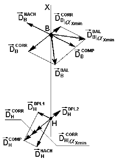
Diagram of counterbalancing calculation
Диаграмма балансировочного расчёта
In this case, the estimated value of the residual transverse displacement of the center of mass from the geometric axis of the FM, which will appear as a result of eliminating the transverse displacement of the center of mass, can be calculated by the following formula
m
BAL
BAL DВ
rB
p CORR
2 DВ CORR М
,
If the condition p CORR < p dop is met, the value D ВA L is defined and the angle position a BAL balancing imbalance vectors DВ BAL , using the corresponding parameters of the unbalance vectors simulated in the regular correc-
tion plane B D В CORR и D Н CORR
.
Balancing vector parameters DВ BAL can be calculated using the following formulas in accordance with the figure representing the geometric sum of imbalances DВ COMP and IDCORR
BAL DВ
D^ MP 2 + D CORR 2 + 2 D COMP D CORR
X
where
f, COMP DВ
a BAL
COMP a В
COMP a В
= arctg
and
and DВ CORR
CORR a В
;
herewith the installation angle of the balancing weight on the upper (standard) correction plane ф BAL will match the phase angle a BAL of imbalance D ^BAL .
Hereafter the FM mass is adjusted by attaching the balancing weight to the balancing plane B, thereby ensuring that both parameters of the mass-inertial asymmetry are brought to values not exceeding the maximum permissible values. In this case the skew of the longitudinal MCAI relative to the geometric axis is eliminated. However, in case the value p KORR exceeds the maximum permissible value p dop , it is necessary to calculate the estimated minimum possible deviation angle of the longitudinal MCAI relative to the geometric axis a X mi n , which can be achieved by changing the imbalance in the correction plane B while reducing the transverse displacement of the center of mass of the FM to the admissible limit value p dop according to the formula
sin a COMP + sin a CORR
a у = —arc sin 2 x X min 2
cos a COMP
+ cos a CORR
COMP
( p dop М D H
CORR a В
– unbalance phase
angles
X
1 - К HR
НВ
COMP
( х В + К НВХН ) D H х н
A I
.
respectively. Then for the case
a OST = 0 , P OST = P CORR < P dop the mass of the balancing weight is calculated according to the formula
In case the reported value a X mi n will exceed the specified admissible limit value, the balancing experiment
is terminated, and the FM will be rejected and sent to the manufacturer for rebuilding due to the calculation that there is no possibility of simultaneously bringing the magnitude of the displacement of the center of mass and the angle of deviation of the longitudinal MCAI relating to geometric axis to values not exceeding the specified maximum admissible limit value. Otherwise, if the inequation |a X min| < a Xdop is correct, the value of the imbalance vector D COR X R mn , ensuring the achievement of the minimum value |a X min| when setting the displacement of the center of mass equal to p dop is determined by the formula
a
BAL
B \ a X
min
= arctg
sin a
COMP В
cos a
COMP В
+ sin a
CORR
B \ a X min
CORR
+ cos a di,.
B \ a X min
BAL m
B \ a Xmin
D BAL
B \ a X min rB
CORR
D B\a X min
COMP p dop М - D H
1 - К
НВ
at the same time, a positive calculation result will mean that the directions of these imbalances D CORR and
B \ a X min
DBCORR coincide, while a negative result, on the other hand, indicates that their directions are opposite. Due to the mutual influence of the correction planes, an imbalance DHORmn will appear in the correction plane Н, which is co-directed to the imbalance DНCOMP , the value of which is determined by the formula p CORR p COMP , p DPL 3 M
D H\ a xmin = D H + D H , (16)
After that, the mass of the FM is adjusted by attaching the balancing weight to the balancing plane B , ensuring that the setting angles of the balancing weight and the vector of the balancing unbalance coincide, and confidence firing of the assembled rotor is performed to confirm the correctness of the calculation. Based on the results of the confidence firing, the parameters of residual imbalances DВ OST and DН OST operating in the corresponding correction planes after setting the balancing weight are determined, and the residual mass and inertial asymmetry parameters are calculated according to a formula (neglecting the mass of the balancing weight, as it is obviously practically insignificant compared to the mass of the controlled FM):
—— a
OST X
—*
P
OST
n OST J_ n OST D B + D H .
M;
p ostv p ostv \
1 . 2 1 D B x B D H xH )
= — arcsin—----------------
2 A Z
where DН DPL 3 – is a value of additional imbalance DН ДPL 3 (not shown in fig. 1), appearing in the correction plane H as a result of the effect of an imbalance D CO in the
В\a X min correction plane B and oppositely directed imbalance DCORRmin . D'DDPL3 is determined by the formula
The performance of the considered algorithm can be estimated using a specific numerical example.
Example of calculating the balance weight. The balancing of the FM will be calculated with the following values of the task parameters:
– model mass М = 100000 g;
– distance from the center of mass of the FM to the upper correction plane xB = 570 mm;
DPL 3 CORR
D H = D B\ a X min К НВ .
Hereafter, the value D BBAL X min and the angular position
a BAL of the vector of balancing imbalance D BAL
B \ a X min B B \ a X min
– radius of the upper correction plane rB = 200 mm;
– distance from the center of mass to the lower plane of correction xH = 800 mm;
– difference between the equatorial and axial moments of inertia Δ I = 8,5∙109 g∙mm2;
– admissible limit value of the transverse displacement of the center of mass p dop = 0,1 mm;
are determined using the appropriate parameters of the imbalance vectors D CORR and D C OMP modeled
B\aX min В in the balancing plane of correction B. After that, the mass of the balancing weight mBAL is determined, the which setting is carried out in the angular position corresponding to the angular position of the imbalance ^ BAL DB\aX min .
To determine the value of the balancing imbalance, mass and setting angle of the balancing load, the following formulas are used:
– admissible limit value of cramp angle of MCAI axdnn = 10' ~ 0,166667°;
Xdop
– influence coefficient of the upper correction plane on the lower correction plane in case of imbalance in the upper correction plane К НВ = 0,3;
– initial imbalance in the upper correction plane D BVACH = 25ooo g .mm, phase angle a NACH = 80°;
– initial imbalance in the lower correction plane D HVACH = 10000 g.mm, phase angle в HA CH = 115°,
BAL
D B \ a X min
COMP 2 CORR 2 COMP CORR
D B + D B \ a X min + 2 D B D B\ a x min

COMP a В
a СОРР
B \ a X min )
X
, (18)
– whence the initial values of the asymmetry parameters of the masses of the FM in accordance with (1) и (2):
p NACH
= 0,34 mm;
p NACH
° X
= 3,62 ' . '
where a CORR mn - unbalance angular p ositi on D C a R An ;
Since it was found that the initial values of the parameters of mass-inertial asymmetry exceed the
specified admissible limit value, we carry out a balancing calculation to achieve the conditions
α O X ST =α X min ≤α Xdop ;
OST ρ ≤ρ dop .
We transfer the FM to the state of quasistatic imbalance, for which we introduce an imbalance DВ COMP with parameters DВ COMP = 25000 g∙mm, phase angle
αCВOMP = 260 °, compensating for the effect of the initial imbalance DВNACH in the upper correction plane. An additional imbalance DHDPL1 will appear in the lower correction plane, the value of which in accordance with (3) will be DHDPL1 = 7500 g∙mm, and the phase angle вHPL1 = 80 °. The imbalance DHPL 1 in total with the imbalance DHNACH in accordance with (4) and (5) will form an imbalance DHCOMP in the lower correction plane with the parameters: DHCOMP = 16707 g∙mm, phase angle βCHOMP = 97.5°. Whence transverse displacement of the center of mass of the FM, in accordance with formula (6), total ρCOMP = 0.167 mm, which exceeds the specified value despite the presence of a skew of the longitudinal MCAI.
Using (7) we calculate the parameters of the corrective imbalance DВ CORR , the action of which in the upper plane of the correction will eliminate the misalignment of the longitudinal MCAI relating to the geometric axis of the controlled flying model: DВ CORR = 12851.5 g∙mm, phase angle α CВORR = 97.5 °. In this case, in accordance with (8) a new additional imbalance vector DH DPL 2 will be formed in the lower correction plane due to the interaction of the correction planes with the parameters: DH DPL 2 =
= 3855.5 g∙mm, phase angle β D H PL 2 = 277.5 °. This, in turn, in accordance with (9) will cause an imbalance DH CORR in the lower plane of correction with the parameters: DH CORR = 12851.5 g∙mm, phase angle β C H ORR = 97.5 °.
To fulfill the condition αCXORR = 0, arising from the equality of the values of the co-directed imbalance vectors DBCORR и DHCORR , the estimated transverse displacement of the center of mass from the geometric axis of the FM in accordance with expression (10) will be ρCORR = 0,257 mm, which exceeds the specified admissible limit value ρdop .
Using formula (14), we calculate the minimum skew angle of the longitudinal MCAI α X min , not exceeding the value α ГЛдоп wherein it is possible to provide a value of the transverse displacement of the center of mass for this FM design equal to ρ dop . As a result of the calculation, we shall obtain: α X min = –8.5', i. e. inequality
α X min ≤α Xdop will be correct. In this case, the minus sign indicates the inclination of the longitudinal MCAI with its upper end towards the geometric axis of the FM.
We shall define the value of the imbalance vector DВ C | O α R X R min in the plane of correction В, ensuring the achievement of the value α X min , according to the formula (15). We shall obtain: DВ C | O α R X R min = 9581,4 g∙mm, phase angle α ВK | O α R X R min = 277,5°. The value of imbalance
D KORR which is co-directional to imbalance D K OMP
Н|αXmin Н we shall define according to the formula (16): DНCO|αRXRmin = = 19581,4 g∙mm, phase angle βCНO|αRXRmin = 97,5°. Moreover, the value of the additional imbalance DНDPL3 , oppositely directed to the imbalance DCORR , will be defined as В|αX min following (17): DНDPL3 = 2874,4 g∙mm, phase angle βDНPL3 = 97,5°.
Using the corresponding parameters of the simulated imbalance vectors D CORR and D C OMP , we shall deter-
В|αXmin В mine the value and the angular position of the vector of the balancing imbalance DВB|AαLX min in the regular correction plane using formulas (18) and (19): DВB|AαLX min = = 34259.3 g∙mm, phase angle α BВ|AαLXmin = 268.75 °.
In accordance with (20) the mass of the balancing BAL weight will be mВ|αX min = 171.3 g, and its setting angle ϕBВ|AαLX min in the correction plane B will coincide with the angle α BВ|AαLXmin , i. e. will be equal to 268.75 °.
To assess the correct operation of the considered algorithm, we shall make sure that the estimated value of the displacement of the center of mass ρ | C α A X L m C in will be a value close to ρ dop after attaching the weights to the FM.
Imbalance value DНBA|αLX min (not shown on figure), oppositely directed to imbalance αBВ|AαLX min , appearing in place of imbalances DНDPL1 and DНDPL3 in the plane of correction Н as a result of the imbalance DBAL , can be В|αX min determined by the formula
BAL BAL
D Н | α X min = D В | α X min К НВ .
Thus: DНBA|αLX min = 10498,8 g∙mm, phase angle βBНA|αLX min = 88,75°. The calculated value of the displace- ment of the center of mass of the FM, omitting the mass of the balancing weight (as insignificantly small), will be defined by the formula:
CALC ρ | α X min
, NACH . NACH f. BAL f. BAL
В + D Н + D В | α X min + D Н | α X min
M
We shall obtain: ρ|CαAXLmCin = 0,11 mm, which practically corresponds to the set value ρdop .
Thus, as a result of the calculation carried out according to the proposed algorithm, the required parameters of the balancing weight were found, the installation of which ensures the fulfillment of condition (23) with a deviation of the longitudinal MCAI from its geometric axis as low as practicable for this FM. Good consistency of the calculated data is confirmed, which proves the correctness of the balancing calculation.
Conclusion. The considered balancing algorithm for a conical flying model in dynamic mode using a single correction plane structurally located at a considerable distance from the center of mass of the model, with optimization according to the criterion of achieving the minimum skew angle of the longitudinal main centroidal axis of inertia, complements the algorithm [1; 2; 12]. The algorithm has been pilot tested with getting positive results on a newly designed vertical dynamic balancing stand with gas supports and is protected by patent of the Russian Federation under No. 2694142 [18]. Work is being carried out to introduce the algorithm into the FM balancing method. The algorithm allows to reduce the number of balancing steps (as a rule, to one step), or by calculation to prove the impossibility of balancing the FM with the given parameters, and, accordingly, reduce the time of the balancing experiment.
References Elaboration and testing of the algorithm which ensures an achievement of minimal deviation angle of flying model’s main centroidal axis of inertia during her counterbalancing in a sole correction flatness
- Klyuchnikov A. V. [Development and improvement of the algorithm single-plane balancing in a dynamic mode of high-speed flying models]. Vestnik SibGAU. 2015. Vol. 16, No. 2, P. 411–416 (In Russ.).
- Klyuchnikov A. V. [Numerical algorithm for the optimization of process trim tapered flying models on dynamic balancing stand]. Vestnik SibGAU. 2016, Vol. 17, No. 2, P. 309–317 (In Russ.).
- Glazyrina L. M., Karpovitskiy M. S., Klyuchnikov A. V., Malgin A. I., Smirnov G. G., Fomin Yu. P. Balansirovochnyy stend s vertikalnoy osyu vrashcheniya [Balancing stand with vertical axis of gyration]. Patent RF, no. 2292533, 2007.
- Glazyrina L. M., Karpovitskiy M. S., Klyuchnikov A. V., Malgin A. I., Smirnov G. G., Fomin Yu. P. Sposob balansirovki rotora [Rotor’s counterbalancing method]. Patent RF, no. 2292534, 2007.
- Dmitriyevskii А. А., Lysenko L. N., Bogodistov S. S. Vneshnyaya ballistika [External ballistics]. Moscow, Mashinostroenie Publ., 1991, 640 p.
- Pravdin V. M., Shanin A. P. Ballistics of uncontrollable flying machines [Ballistika neupravlyaemih letatelnih apparatov]. Snezhinsk, RFNC-VNIITF Publ., 1999, 496 p.
- Klyuchnikov A. V. [The algorithm of single-plain dynamic balancing process of a conical flying prototype with optimization by criteria of achieve the minimum deviation of main centroidal axis of inertia]. Materialy XXIII Mezhdunarodnoy nauchnoy konferentsii “Reshetnevskie chteniia” [Proc. 23th Int. Technol. Conf. “Reshetnev reading”]. Krasnoyarsk, 2019, Part 1, P. 30–32 (In Russ.).
- Ilinykh V. V., Klyuchnikov A. V., Mihailov E. F., Timoshchenko A. G. [Technological support of quality during the manufacture of hypersonic uncontrollable flying models]. Vestnik SibGAU. 2013, Vol. 49, No. 3, P. 191–196 (In Russ.).
- Klyuchnikov A. V. [Method of eliminate a technological rig on measurement results during dynamic counterbalancing of flying vehicle]. Materialy XIX Mezhdunarodnoy nauchnoy konferentsii “Reshetnevskie chteniia” [Proc. 19th Int. Technol. Conf. “Reshetnev reading”]. Krasnoyarsk, 2015, Part 1, P. 21–23 (In Russ.).
- Abyshev N. A., Klyuchnikov A. V., Mikhailov E. F., Chertkov M. S. [Stand for precise non-contactable counterbalancing in dynamic regimen of conical rotors]. Trudy XIX Mezhdunarodnogo simpoziuma “Nadyozhnost i kachestvo” [Proc. 19th Int. Technol. Symp. “Reliability & Quality”]. Penza, 2014, Vol. 2, P. 234–236 (In Russ.).
- Klyuchnikov A. V. [Test equipment for diagnostics of a mass symmetry distribution of compound rotor’s detailes]. Trudy IX Mezhdunarodnoy nauchnoprakticheskoy konferentsii “Innovatsii na osnove informatsionnyh i kommunikatsionnyh tehnologiy” [Proc. 9th Int. Scientif. and Pract. Conf. “Innovations Based on Information and Communication Technologies”]. Moscow, 2012, Part 1, P. 21–23 (In Russ.).
- Klyuchnikov A. V. Sposob balansirovki rotora v odnoy ploskosti korrektsii [Method of rotor’s counterbalancing in singular place for correction]. Patent RF, no. 2499985, 2013.
- Klyuchnikov A. V. [Precised mathematical model for valuing of mass-inertia asymmetry parameters of a lengthened rotor]. Trudy XVII Mezhdunarodnogo simpoziuma “Nadyozhnost i kachestvo” [Proc. 17th Int. Technol. Symp. “Reliability & Quality”]. Penza, 2013, Vol. 1, P. 224–227 (In Russ.).
- Andreev S. V., Klyuchnikov A. V., Mihailov E. F. [Prospects of application of dynamic counterbalancing method for testing of flying machine’s mass-inertia asymmetry parameters]. Materialy XVIII Mezhdunarodnoy nauchnoy konferentsii “Reshetnevskie chteniia” [Proc. 18th Int. Technol. Conf. “Reshetnev reading”]. Krasnoyarsk, 2014, Part 1, P. 8–10 (In Russ.).
- Klyuchnikov A. V. Sposob nastroiki balansirovochnogo stenda dlya opredeleniya parametrov massoinertsionnoy asimmetrii rotorov [Method of adjusting a counterbalance machine for determination of rotors’ mass-inertia parameters]. Patent RF, no. № 2453818, 2013.
- Klyuchnikov A. V. [Methodical ensuring a process of individual adjusting the dynamic balancing machine in the controlled object]. Trudy XIV Mezhdunarodnoy nauchno-prakticheskoy konferentsii “Innovatsii na osnove informatsionnyh i kommunikatsionnyh tehnologiy” [Proc. 14th Int. Scientif. and Pract. Conf. “Innovations Based on Information and Communication Technologies”]. Moscow, 2017, P. 382–386 (In Russ.).
- Andreev S. V., Klyuchnikov A. V., Lysykh A. V., Mikhailov E. F. [Calibrate operations during detail’s module counterbalancing on a non-adjusted dynamic counterbalance machine]. Trudy XVIII Mezhdunarodnogo simpoziuma “Nadyozhnost i kachestvo” [Proc. 18th Int. Technol. Symp. “Reliability & Quality”]. Penza, 2013, Vol. 2, P. 129–131 (In Russ.).
- Klyuchnikov A. V. Sposob balansirovki rotora v odnoy ploskosti korrektsii [Method of rotor’s counterbalancing in singular place for correction]. Patent RF, no. 2694142, 2019.
