Engineering and design of a roller for soil tillage

Author: Smirnov K.A.
Journal: Научный журнал молодых ученых @young-scientists-journal
Section: Технические науки
Article in issue: 3 (38), 2024.
Free access
This paper considers the issues related to the working process of a soil tillage roller. Characteristic changes in the design of the roller and its working elements are noted. The peculiarities of the design of the proposed soil tillage roller are presented. The main indicators characterizing the working process of the soil tillage roller are given.
Soil tillage, roller, working process, working element, agrotechnical period
Short address: https://sciup.org/147244373
IDR: 147244373 | UDC: 631.314.1
Проектирование почвообрабатывающего катка
В данной статье рассмотрены вопросы, связанные с рабочим процессом почвообрабатывающего катка. Отмечены характерные изменения в конструкции катка и его рабочих элементов. Показаны особенности конструкции предлагаемого почвообрабатывающего катка. Приведены основные показатели, характеризующие рабочий процесс почвообрабатывающего катка.
Text of the scientific article Engineering and design of a roller for soil tillage
Introduction. Rolling as a tillage technique includes harrowing, levelling and partial mixing of the soil. However, the most important aspect of this technique is still soil compaction, which consists of changing the mutual arrangement of the soil particles by reducing the soil volume. At higher densities, the seed contact with the soil is better, which favors better moistening of seeds. The higher the moisture and temperature of the top layer of soil, the faster the seeds will germinate. At the same time, the nutrients in the seed are used more sparingly. Sprouts appear faster, they are more uniform and stronger.
The purpose of the work was to substantiate the design of a tillage roller for presowing tillage both as part of a separate implement and as part of combined units that may include ploughs or cultivators.
Materials and methods of research. The main working bodies for loosening, levelling and compacting the soil of the proposed design of the tillage roller are bars, wire working elements and cleaners.
It has been established that the disadvantage of the design of tooth loosening working elements is the periodic winding up of plant residues, which reduces the quality indicators of surface tillage and requires time for stops to restore the quality indicators of the tillage roller [2].
Therefore, a new design of the working elements of the rod tillage roller in the form of spring convex rods is proposed [5]. As the roller travels across the field, the contact with the soil causes it to rotate. Due to the weight of the roller, spring convex rods 6 of working elements 5 penetrate into the soil and due to their elastic forces and angle of attack, they cut, destroy clods of soil with simultaneous displacement, loosening and levelling of the field micro-relief, as well as self-cleaning of the roller surface from soil and plant residues (Fig. 1).
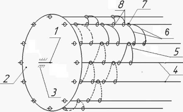
Figure 1 – Scheme of the rod-and-mesh tillage roller:
1 – axle; 2 – disc; 3 – bearing; 4 – bar; 5 – working element;
6 – rod; 7 – spring; 8 – fasteners
However, to extend the terms of spring field works it is required that the working bodies of tillage machines can work in conditions of maximum permissible soil moisture.
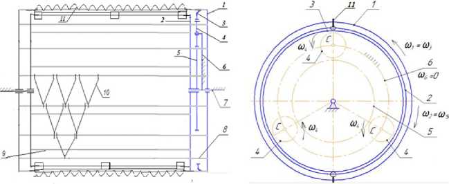
The proposed design of the tillage roller is developed and made in the laboratory of the Department of “Agricultural Machinery” of the Institute of Mechanical and Power Engineering named after V.P. Goryachkin of the Russian State Agrarian University – Moscow Timiryazev Agricultural Academy in cooperation with the Centre for Technological Support of Education (Fig. 2) [1, 4].
a b
Figure 2 – Schematic diagram of the tillage roller: a – front view; b – side view
1 – driving roller; 2 – driven roller; 3 – central crown gear; 4 – satellites; 5 – sun gear; 6 – driver; 7 – axle; 8 and 9 – bars; 10 – working elements; 11 – scrapers
When the tillage roller moves on the field on heavy clay soils, driving roller 1 is set in rotation by the contact with the soil of bars 8 with working elements 10 and central crown gear 3 rotates satellites 4 around its own axis with angular speed ώ4. The rotation of the satellites 4 causes the rotation of movable sun gear 5, which provides the rotation of the connected driven roller 2 (ώ2=ώ5). The system of fixation of driver 6 (ώ6=0) provides the rotation of driven roller 2 in the opposite direction relative to driving roller 1. Scrapers 11 are in contact with bars 8 and with working elements 10 and provide the cleaning of the working elements of driving roller 1.
Driven roller 2 rotates at a higher speed than driving roller 1, but in the opposite direction. The part of the soil under the action of the tillage roller is subjected to repeated impacts from elastic bars 9 and scrapers 11 of driven roller 2. The counter-rotation of driving roller 1 and driven roller 2 increases the impact force on soil lumps and improves the soil crumbling index, and scrapers 11 ensure cleaning of elastic bars 8 and working elements 10 from soil.
However, working on sandy soils or peat does not require much effort in crumbling lumps of soil, therefore, it is rational to apply a tillage roller in which driven roller 2 rotates at a higher speed than driving roller 1, but in the opposite direction, while also providing cleaning of the working surface of the leading roller from soil sticking and plant residues. In this case, the sequence of connection of parts of the planetary gearbox with the parts of the tillage roller is changed.
Results and discussion. This design of the tillage roller reduces energy consumption during soil preparation for sowing and can be used as a tool of a combined aggregate as part of a plough [3, 6].
Justification of the working process of the proposed tillage roller allows to conclude that when the roller moves along the field surface, an increase in the sliding coefficient can be observed due to the additional load on the leading roller from the drive mechanism of the driven roller, which will lead to an improvement in the soil crumbling index.
The joint operation of the driving and driven rollers provides levelling of the soil surface, improvement of the soil crumbling index, while producing a compacted soil layer at the seed embedment depth covered with loose soil, as well as self-cleaning of the driving roller surface from soil and plant residues [7].
Conclusions. The design features of the proposed tillage roller allow for continuous preparation of the field surface, processed to the required depth with the required looseness and density in conditions of increased soil moisture, which will extend the spring agrotechnical period.
References Engineering and design of a roller for soil tillage
- Mechanization of crop production (terms and definitions): Textbook / N.V. Aldoshin [et al.]. Moscow: OOO Sam Poligrafist, 2021. 260 p.
- Author's certificate SU No. 1276270, IPC A 01 B 29/04, 1986 Tillage roller / Yu.A. Shutov Yu.V. Bulletin No. 46.
- Patent No. 211830, IPC A01B 29/04. Tillage roller / V.I. Patent holder FSBEI HE RSA - Moscow Agricultural Academy named after K.A. Timiryazev. № 2022105078, filed 25.02.2022; published 24.06.2022. Bulletin № 18. 5 p.
- Patent № 209650, IPC A01B 29/04. Tillage roller / V.I. Plyaka, S.M. Katkova, M.A. Mekhedov; patent holder FSBEI HE RSATU - Moscow Timiryazev Agricultural Academy. № 2021134659, filed 26.11.2021; published 17.03.2022. Bulletin № 8. 5 p.
- Patent № 215975, IPC A01B 29/04. Tillage roller / V.I. Plyaka, S.P. Kazantsev; patent holder FSBEI HE RSA - Moscow Timiryazev Agricultural Academy. № 2022124714, declared 20.09.2022; published 11.01.2023. Bulletin № 2. 5 p.
- Comparative tests of ridging cultivators with active and passive working tools. / Andrey Panov and etc // E3S Web of Conferences. Series. «International Scientific Conference «Construction Mechanics, Hydraulics and Water Resources Engineering, CONMECHYDRO 2021, P. 04017.
- Ploughing quality and energy consumption depending on plough bodies type. (Scopus) / Y.P. Lobachevsky and etc // IOP Conf.Series: Materials Science and Engineering 1030 (2021) 012154.
