Enhancing the Capacity of Stratospheric Cellular Networks Using Adaptive Array Techniques

Author: Sultan Aljahdali
Journal: International Journal of Computer Network and Information Security(IJCNIS) @ijcnis
Article in issue: 6 vol.5, 2013.
Free access
In this paper, the capacity of stratospheric cellular communications is improved by optimizing the amplitude feeding of the concentric rings array (CRA). The weighting profile of this array is chosen to be a cosine function raised to some power to control the beam pattern used in the cellular coverage. The power of this function is optimized to reduce the resulted sidelobe levels which increase the carrier-to-interference ratio (CIR) within the cells. It is found that increasing the power of the cosine function will reduce the sidelobe levels especially at lower number of elements in the innermost ring with a minor increase in beamwidth. For an innermost ring of 3 elements in a 10 rings CRA, a sidelobe level of 45 dB can be obtained below the mainlobe level. The simulation results show that a CIR of up to 38dB can be achieved and a minimum of 28dB at the cell borders is guaranteed with a 0.95 coverage ratio.
Array Processing, Concentric Ring Arrays, Stratospheric Cellular Communications
Short address: https://sciup.org/15011195
IDR: 15011195
Text of the scientific article Enhancing the Capacity of Stratospheric Cellular Networks Using Adaptive Array Techniques
Published Online May 2013 in MECS
The demand for cellular mobile communications services is growing at an explosive rate with the anticipation to provide anyone, anywhere, and at anytime with services at low cost and high quality services. Therefore there is a challenge to find solutions for increasing the system capacity and quality of service at an affordable cost. Recently, an innovated communications system based on utilizing high altitude stratospheric platforms [1-3] has a great interest especially for mobile and wireless data communications. The platforms are known under different names as High-Altitude Platforms (HAPs), High Altitude Aircraft and Airships (HAAS), High Altitude Aeronautical Platforms (HAAPs), High Altitude Long Endurance Platforms (HALE Platforms), Stratospheric Platforms (SPs), etc. They are located at 17–22 km above the earth surface and the International Telecommunications Union (ITU) has allocated the spectrum of 600 MHz at 47/48 GHz (shared with satellites) worldwide specifically for HAPs services. HAPs are also authorized to be used in some 3G services (around 2 GHz) and fixed services in 31/28 GHz in some countries.
There is also a potential use of the bands in the range 3–18 GHz by HAPs in the fixed and mobile services.
These standardization activities confirm the attention paid all over the world to this technology. The quasi-stationary aerial platforms operating in the stratosphere preserve many advantages of both terrestrial and satellite systems but also provide special advantages of their own [3].
One of the most important business sectors open for SP applications is Telecommunications and Informatics and specific services that could be provided are: very wideband Internet, entertainment video and audio, videoconferencing, cellular telephony, broadband services, access provision to digital network, etc. Moreover, SPs can provide solutions for special geographical regions or emergency applications (disasters, earthquakes, etc.) supporting multimedia services at satisfactory quality.
Despite the various optimistic features of SPs, there are some challenging issues that must be explored and require research and developments. At most importance is the radio coverage and antenna used to form the ground cells. Many studies dealt with the antenna configurations and types used for best coverage [4-9] but still require research and development. Spot-beam antennas or such as lens antennas [10] suffer from the lack of flexibility in design and once have designed cannot be reconfigured again which is an important feature required for SPs. On the other hand, in [11], the utilization of antenna arrays with adaptive beamforming requires heavy processing loads to obtain the required antenna pattern and make it very hard for real application. Recently, some literatures [12-17] dealt with the application of concentric rings array (CRA) to develop the cellular coverage for SPs, where it has many advantages over other array configurations such as the independent azimuth beamforming and ease of feeding. On increasing the capacity of SPs networks we must reduce the sidelobe levels in the radiation pattern of these arrays because it interferes with the other cochannel cells. Therefore, this paper is devoted to develop an array feeding function that can be adjusted to reduce the sidelobe levels towards the other cochannel cells and hence improve the carrier-to-interference ratio (CIR). This function is chosen to be a cosine function raised to some power which is optimized to the desired response. The paper is arranged as follows; section 2 introduces the theory and construction of CRA and section 3 discusses the beamforming of CRA using the cosine function profile and the resulted beamwidth and sidelobe levels variation. In section 4, we introduce the design aspects of SP cellular system using CRA with cosine feeding profile and in section 5 we discuss the coverage performance using different cosine profiles. Finally, section 6 concludes the paper.
II. CRA Beamformer
In this section, we describe the geometry of the CRA and state its related beamforming equations. The CRA as shown in Fig. 1 is formed by a number of concentric ring arrays. The arrangement of elements in CRA contains multiple concentric circular rings which differ in radius and number of elements and this gives arise to different radiation patterns. In this Figure, there are M concentric circular rings. The m th ring has a radius r and a number of elements Nm where m = 1,2,..., M . Assuming that the elements are uniformly spaced within the ring so it has an element angular separation given by:
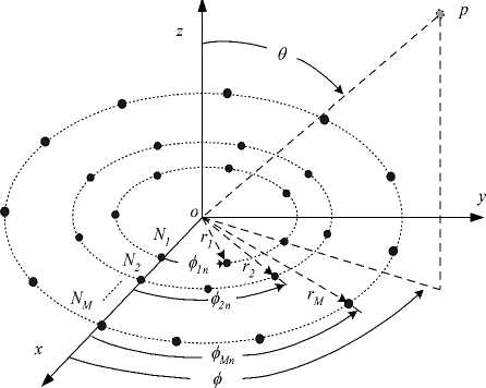
Figure 1: Geometry of concentric circular antenna array.
V m
2 n
N m
and the elements in this ring are therefore located with an azimuth angle measured from the x-axis given by:
ф = n v , n = 1,2,...., N (2)
mn m , , ,, m
Assuming an observation point P located at a distance r form the origin, the measured far field at this point will be:
e jkr M Nm
E ( r , 6 , ф} = --- ZZ W m
Г m = 1 n = 1
e
jkrm sin
6 cos ( ф - Ф mn )
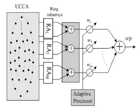
Figure 2: Beamformer for CRA
where k = — is the wave number and w is the X mn excitation coefficient (amplitude and phase) of the mn th element. From (3), we can deduce an expression for the array steering matrix by first defining the array steering vector for a single ring and extending the analysis for the whole array. The array steering vector for the mth ring will be [16]:
where a is an exponent that controls the sidelobe reduction. Fig. 3 shows the tapering function at different values of a for an array of 20 concentric rings. This factor as will be seen in the subsequent section can be optimized to have lower sidelobe levels.
We can write the amplitude weight vector of the m th ring subarray as follows:
Wm = wm SCm (6)
S ( 6 ф ) = [ e jk”* sin 6 cos ( ф - ф m 1 ) e™"" sin 6 cos ( Ф-ф m 2 ) e jkrm s™ 6 cos ( ф Ф mNm ) ] T
In Fig. 2, the beamformer proposed for CRA will weight all elements in an individual ring with the same value. This weighting value is denoted by wm where m = 1: M and is proposed as:
wm = cosa((^) T)^, m =1,2,..., .M (5)
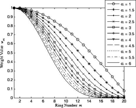
Figure 3: The ring subarrays weights, as a function of the ring number at different values of the cosine power, .
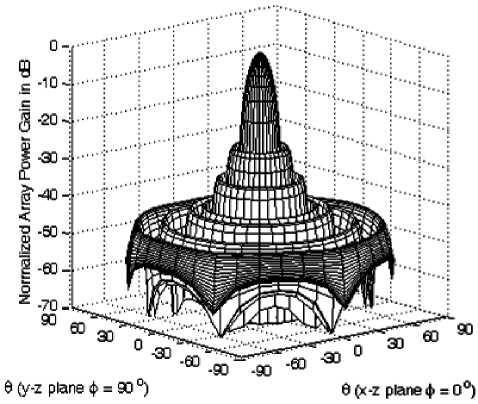
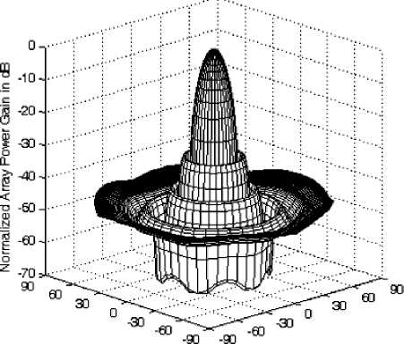
Figure 4-a: The normalized power pattern of CRA of =3 and =10 at =1.
where (0 o , Ф о ) is the direction of the mainlobe and S cm Ф. , Ф о ) is the m th ring steering vector at this direction.
The array factor or gain in this case will be:
( ,∅)=∑ ( ,∅) (7)
or
( ,∅)=∑ (( 2-1) )
( ,∅ ) ( ,∅)
m=l x7
and the normalized array power pattern will be:
( ,∅)=( |( ,∅)|
∑ (( ))
The power pattern is preferred to be in dB, therefore it will be:
( ,∅) =20log| ( ,∅)|
-
- 20log∑ (( 2-1) ) m=l x 7
As depicted in the last two equations that the array power gain depends on the array weighting, the total number of rings in the array, the number of elements in each ring subarray and finally the direction of observation. The maximum gain of the CRA depends the cosine power, the number of rings and number of elements in each ring.
The incremental number of elements in the outward rings is chosen as 6 elements to provide almost half of the wavelength separation between the neighboring elements in a ring and between the neighbored rings [16].
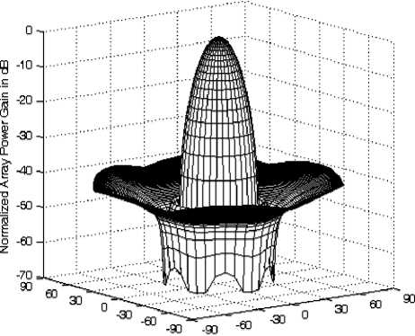
The 3-dimensional power patterns shown in Fig. 4-a to 4-c are drawn at different values of a which are 1, 2 and 5 respectively.
6 (y-z plane ф = 90 °) 8 (x-z plane ф = 0°)
Figure 4-b: The normalized power pattern of CRA of =3 and =10 at =2.
8 (y-z plane ф = 90 °) 8 (x-z plane ф = 0°)
Figure 4-c:The normalized power pattern of CRA of =3 and =10 at =5.
An important notice from these figures is that the power pattern is almost independent on the azimuth angle ( ϕ ) which is a desired property for the design of SP cellular system. Another point worth noting is that the sidelobe level will be reduced by increasing the value of α especially the nearest sidelobes while it is slightly raised in the directions close to 9 =90 degrees.
A detailed analysis of the CRA parameters with cosine weighting will be discussed in the next section in terms of the variation of the beamwidth and sidelobe levels.
-
III. CRA Performance Study
-
3.1 Beamwidth Performance
Under the proposed array feeding function, we will explain the CRA performance in terms of the beamwidth and the sidelobe levels.
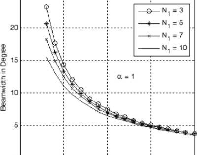
Starting with the beamwidth analysis as shown in Fig. 5-a to 5-e, we found that increasing the value of α from 1 to 5 will increase the beamwidth at the same array geometry, i.e. with the same number of elements of the innermost ring and the total number of rings. This increase in beamwidth is due to the increase in tapering effect of the weights as α increases. On the other hand at the same value of α , the beamwidth will decrease by either increasing the number of rings in the array or increasing the innermost ring size and both are due to the increased array directivity. According to these figures, we can design an array to form a beam of certain cross section and hence determine the required number of elements in innermost ring, the number of elements in each ring and the cosine profile used (i.e. the value of α ).
О
О 5 10 15 20
Number of Rings
Figure 5-a: Beamwidth variation with the number of rings at different sizes of the innermost ring and at a =1.
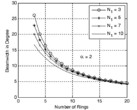
Figure 5-b: Beamwidth variation with the number of rings at different sizes of the innermost ring and at a =2.
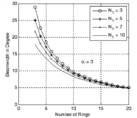
Figure 5-c: Beamwidth variation with the number of rings at different sizes of the innermost ring and at a=3.
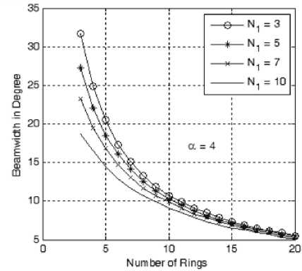
Figure 5-d: Beamwidth variation with the number of rings at different sizes of the innermost ring and at a =4.
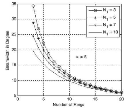
Figure 5-e: Beamwidth variation with the number of rings at different sizes of the innermost ring and at a =5.
-
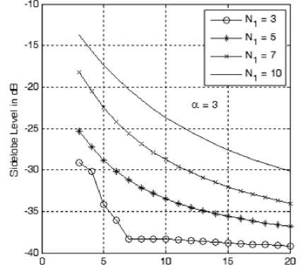
3.2 Sidelobe Level Performance
The other important array parameter is the sidelobe level. The sidelobe level is considered as the level of the nearest sidelobe to the mainlobe and actually the other sidelobes are lower in levels. As shown in Fig. 6-a to 6-e, the sidelobe level varies with both the innermost ring size, number of rings and the cosine power, α . Increasing the size of the innermost ring has the effect of reducing the sidelobe level with the other parameters kept constant. Also the sidelobe level is reduced by increasing number of rings (due to the increase in the array directivity) and increasing the cosine power, α . Therefore in a cellular design, we trade off the number of rings with the required sidelobe level by adjusting the innermost ring size and the value of α .
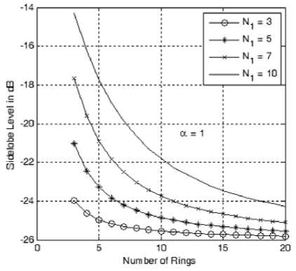
different sizes of the innermost ring and at a =1.
Figure 6-a: Sidelobe level variation with the number of rings at
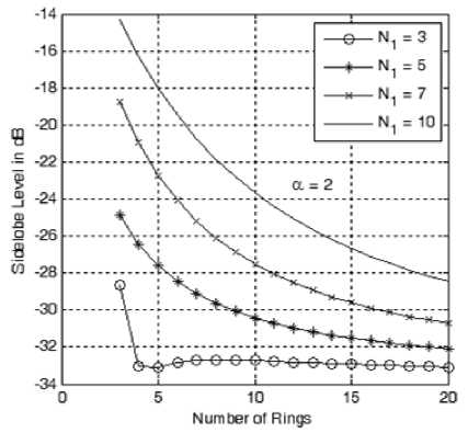
Figure 6-b: Sidelobe level variation with the number of rings at different sizes of the innermost ring and at a =2.
Number of Rings
Figure 6-c: Sidelobe level variation with the number of rings at different sizes of the innermost ring and at a=3.
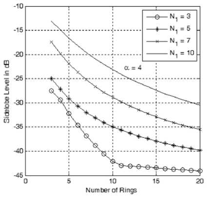
Figure 6-d: Sidelobe level variation with the number of rings at different sizes of the innermost ring and at a =4.
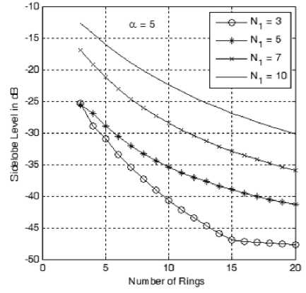
Figure 6-e: Sidelobe level variation with the number of rings at different sizes of the innermost ring and at a =5.
Where Pt is the transmitted cell power, A^ ( ,∅ ) is the transmitting CRA gain at the direction towards the mobile, AT ( ,∅ ) is the mobile station receiving gain and X is the carrier wavelength. From this equation, we find that the received power at a specific frequency depends on the transmitted power from the SP, the CRA and MS gains and the SP height h . In determining the cell footprint, we should find the received power on the ground and in this case we should also normalize (11).
Assuming that the ms has a unity gain (i.e. A ( 9 ,∅ )=1 ), therefore the normalized received power will be given by:
Pm( ,∅ )="( 71 ,∅ 2) At( ,∅ )cos2 ()
pt()
or
Prn( ,∅ )=KAt( ,∅ )cos2( )(13)
IV. SP Cell Footprint using CRA
In this section we adopt the CRA for the coverage of SP cellular system. As shown in Fig. 7, the SP cell is formed using either spot-beam antennas or antenna arrays onboard an airship SP located at a height h from the ground. In this paper we utilize the CRA which can be reconfigured to provide flexibility in the cell design.
The received signal on the ground at a mobile station ( ms ) of direction ( ,∅ )is given by [17]:
Pr ( ,∅ )=
Mt ( ,∅ ) Ar ( ,∅ )(777 ) cos2( ) (11)
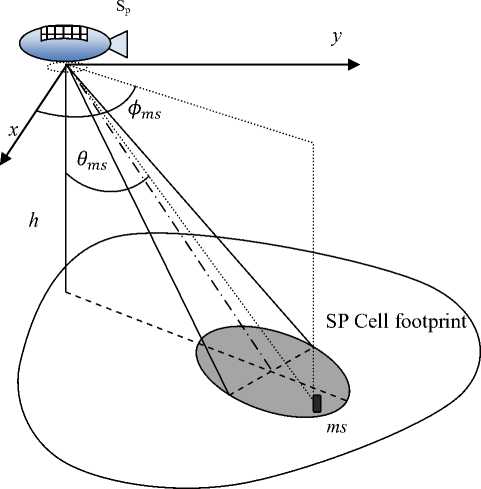
Figure 7: SP cell formed using SP located at altitude of h km from the ground.
where K is a constant.
From (13), it is found that the cell footprint depends on both the transmitting array power gain and the user location within the cell. The squared cosine factor in this equation is due to the variable range from the SP to the ms within the cell which in turn will vary the received power also.
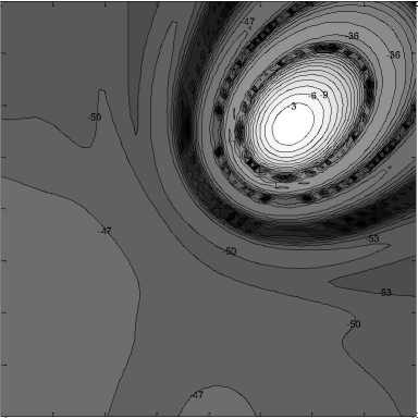
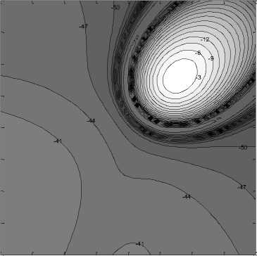
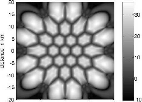
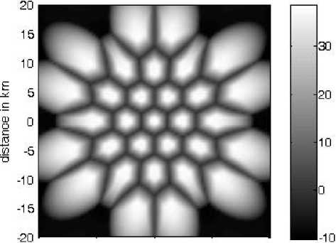
Figs. 8-a to 8-c depict a cell formed by a beam of mainlobe direction Pq =30 and Фо =45 using CRA of 10 rings with an innermost ring size of 3 elements at a =1,2,5 respeitvely. The cell boundary may be defined as the 3dB contour on the ground and any received power outside this contour is called out-of-cell radiation. The normalized power received in these figures has out-ofcell peaks due to the different sidelobes of the CRAs used. Of these figures the case where a = 5 has the lowest received out-of-cell power with a wider cell area due to the increased tapering of the cosine function.
-5
-10
-15
-20
-20 -15 -10
-3

-5 0 5 10 15 20
distance in km
Figure 8-a: Normalized power illumination for a beam of
mainlobe direction 9q =30 and Фо =45 using CRA of 10 rings with an innermost ring size of 3 elements at a =1
-5
-10
-15
-10
-20
-30
-40
-50
-60
-70
-20 -15 -10
-5 0 5 10 15 20
distance in km
-20
-80
-20
Figure 8-b: Normalized power illumination for a beam of mainlobe direction 60 =30 and Фо =45 using CRA of 10 rings with an innermost ring size of 3 elements at a =2
-5
-10
-15
-20 -15 -10 -5 0 5 10 15 20
distance in km

-10
-20
-30
-40
-50
-60
-70
-80
Figure 8-c: Normalized power illumination for a beam of mainlobe direction 60 =30 and Фо =45 using CRA of 10 rings with an innermost ring size of 3 elements at a =5
-
V. CIR Performance using CRA
On determining the coverage performance of SP cellular system, we will build a cellular system consisting of 121 cells and choose a reuse factor of 4. The first group of cochannel cells shown in Fig. 9 will be examined where the innermost cell is formed by a beam of cross section beamwidth of 7.2 degrees to give microcell coverage.
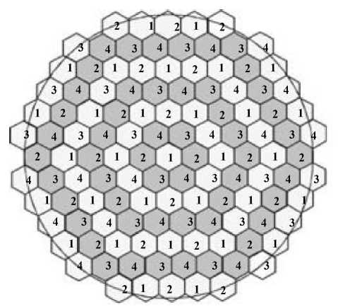
Figure 9: Cellular SP system formed by 121 cells at frequency reuse factor of 4.
The CIR can be defined (at the worst case) as the ratio the desired signal power to the sum of all cochannel lls powers within the cell area. In [11] a general method used to calculate CIR as:
CIR = (14)
Pto tai Ртах
Where ^total is the total received power (desired plus channel signals) and ^max is the maximum received nal. As expected, decreasing the sidelobe levels by ofiling the cosine feeding function will improve the ulted CIR as shown in Figs. 10-a to 10-c. In these ures, the illuminated out-cell-regions is resulted from e higher sidelobe levels as in Fig. 10-a where the value of a =1 and the array is constructed by^1 =3 and M =11. In Figs. 10-b and 10-c the CIR will be improved by choosing higher values of a at the expense of the increased number of rings.
The CIR improvement can be clarified by discussing the coverage ratio which is defined by the ratio of areas within a cell that covered with at least a certain CIR value to the total cell area. The coverage ratio at CRAs used in Figs. 10-a to 10-c is shown in Fig. 11. The resulted decrease in the sidelobe level will result in a more falling curve as at a =5 with more ratios of higher CIR. At a =1 a minimum of 17.5 dB and maximum of 32 dB for the CIR levels are obtained while for a =2, we have a minimum of 22 dB and a maximum of 36 dB. For a =5, the minimum CIR is 21.5 dB while the maximum is 38. Actually, the minimum and maximum values of CIR do not give the complete view on the performance and the coverage ratio profile must be taken into consideration. For example at a =5, about 70% of the cell area has a minimum CIR of 35 dB while at a =2 only 2% of the cell area is covered with the same value. In general a good coverage and distribution of CIR can be obtained by making the coverage curves of higher slopes and near the higher maximum of CIR.
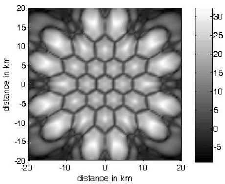
Figure 10-a: CIR variation at a =1 and the array is constructed by Ni =3 and M =11.
-20 -10 0 10 20
distance in km
Figure 10-b: CIR variation at (X =2 and the array is constructed by Ni =3 and M =12.
-20 -10 0 10 20
distance in km
Figure 10-c: CIR variation at (X =5 and the array is constructed by Ni =3 and M =17.
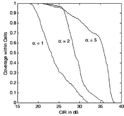
Figure 11: Coverage ratio and the CIR distribution for the three CRAs designs in Figs. 10-a to 10-c.
-
VI. Conclusions
SP Cellular communications is an emerging technology that can provide many innovated solutions compared to conventional systems. The radio coverage from SPs is a paramount issue which has an impact on the overall system performance. In this paper, the improvement of the system capacity in terms of CIR was discussed through an adaptive feeding for the concentric ring arrays (CRAs). The feeding profile of this array was discussed where a cosine function raised to some power is proposed as an amplitude weighting and its power is optimized for the lowest sidelobe level. It is found that increasing the cosine power will reduce the sidelobe level at the expense of beamwidth increase which can be tailored by increasing the number of rings in the array. The sidelobe levels obtained can be 47dB lower than the mainlobe especially at lower sizes of the innermost ring. The results show that a CIR of 38 dB can be obtained within the cells with a minimum of 21.5 dB almost at the cell edges.
References Enhancing the Capacity of Stratospheric Cellular Networks Using Adaptive Array Techniques
- A. Mohammed and Z. Yang, "Broadband Communications and Applications from High Altitude Platforms", International Journal of Recent Trends in Engineering, Vol 1, No. 3, May 2009.
- A. Mohammed and T. Hult, Capacity Evaluation of a High Altitude Platform Diversity System Equipped with Compact MIMO Antennas", ACEEE International Journal on Communication, Vol 1, No. 1, Jan 2010.
- S. Karapantazis and F. Pavlidou, "Broadband communications via high-altitude platforms: a survey," IEEE Communications Surveys & Tutorials, vol. 7, pp. 2-31, 2005.
- M. Oodo, R. Miura, Y. Hase, T. Inaba, T. Sakamoto, and M. Suzuki, "Measurement results of digital
- beamforming array antenna on-board stratospheric platform in the band 31/28 GHz", Proceeding of 5th International Symposium on Wireless Personal Multimedia Communications, Honolulu, Hawaii, October 2002.
- E. Falletti, L. Lo Presti, and F. Sellone, "He LOST - Heliplat LOcalization SysTem based on smart antennas technology", Proceeding of IEEE 56th Vehicular Technology Conference, VTC Fall 2002, September 2002.
- Z. Xu, Y. Zakharov, and G. White, "Vertical antenna array and spectral reuse for ring-shaped cellular coverage from High Altitude Platform", Loughbourgh Antennas and Propagation Conference (LAPC 2006), November 2005.
- T. Isernia, F. J. Ares Pena, O. M. Bucci, M. D'Urso, J. F. Gomez, and J. A. Rodriguez, "A hybrid approach for the optimal synthesis of pencil beams through array antennas", IEEE Transactions Antennas and Propagation, Vol. 52, No.11,pp. 2912–2918, 2004.
- J. Thornton, D. Pearce, D. Grace, M. Oodo, K. Katzis and T. C. Tozer, "Effect of Antenna Beam Pattern and Layout on Cellular Performance in High Altitude Platform Communications", International Journal of Wireless Personal Communications, Springer, pp. 35-51, 2005
- G. White, E. Falletti, Z. Xu, D. Borio, F. Sellone, Y. Zakharov, L. Lo Presti, F. Daneshgaran "Report on adaptive beamforming algorithms for advanced antenna types for aerial platform and ground terminals", CAPANINA Project, Deliverable No. D17, 31st Jan 2006.
- J. Thornton, "A Low Sidelobe Asymmetric Beam Antenna for High Altitude Platform Communications", IEEE Microwave and Wireless Components Letters, Vol. 14, No. 2, pp. 59-61, February 2004.
- J. Thornton and D. Grace. "Optimizing an array of antennas for cellular coverage from a High Altitude Platform", IEEE Transactions Wireless Communications, Vol. 2, No. 3, pp. 484–492, May 2003.
- Y. Albagory, M. Dessouky, H. Sharshar, "Efficient Sidelobe Reduction Technique for Small-Sized Concentric Circular Arrays", Progress In Electromagnetics Research, PIER 65, pp. 187-200, 2006.
- Y. Albagory, M. Dessouky, H. Sharshar, "Optimum Normalized-Gaussian Tapering Window for Side Lobe Reduction in Uniform Concentric Circular Arrays," Progress In Electromagnetics Research, PIER 69, pp. 35 –46, 2007.
- Y. Albagory, M. Dessouky, H. Sharshar, "An Approach for Dolph-Chebyshev Uniform Concentric Circular Arrays," Journal of Electromagnetic Waves and Applications, JEMWA, Vol.21, No.6, pp.781 –794,2007.
- S. C. Chan, and H. H. Chen, "Uniform Concentric Circular Arrays with Frequency-Invariant Characteristics—Theory, Design, Adaptive Beamforming and DOA Estimation", IEEE Transactions on Signal Processing, Vol. 55, No. 1, pp. 165-177, January 2007.
- Y. Albagory, M. Dessouky, H. Sharshar, " An Approach for Low Sidelobe Beamforming in Uniform Concentric Circular Arrays" International Journal of Wireless Personal Communications, vol. 43, no. 4, pp. 1363-1368, 2007, Springer.
- Y. Albagory, "A Novel Design of Arbitrary Shaped Cells for Efficient Coverage from High Altitude Platforms" Progress In Electromagnetics Research Letters, Vol. 1, 245-254, 2008.
- J. Thornton, "A Low Sidelobe Asymmetric Beam Antenna for High Altitude Platform Communications", IEEE Microwave and Wireless Components Letters, Vol. 14, No. 2, pp. 59-61, February 2004.
- Moawad Dessouky, Hamdy Sharshar, Yasser Albagory "Improving The Cellular Coverage from A High Altitude Platform by Novel Tapered Beamforming Technique," Journal of Electromagnetic Waves and Applications, JEMWA, Vol.21, No.13, pp. 1721 –1731, 2007.
- Mostafa Nofal, Yasser Albagory, Mohiy Hadhoud, Moawad Dessouky, "A Novel Cellular Structure for Stratospheric Platform Mobil Communications ", Proc. of the Nineteenth National Radio Science Conference, NRSC'2002, March 19-21, Faculty of Engineering, Alexandria University, Alexandria, EGYPT, 2002.
- Mostafa Nofal, Yasser Albagory, Moawad Dessouky, Hamdy Sharshar, "Modeling and Investigating the Rotational Motion Effects of the High Altitude Platforms," Twenty Second National Radio Science Conference (NRSC 2005) March 15-17, 2005 Cairo – Egypt.
- Xu, Z. Zakharov, Y. White, G., "Antenna array optimisation using semidefinite programming for cellular communications from HAPs", IEEE Electronics Letters, Vol. 43, no. 2, pp. 67-69, 2007.
