Ensuring the required accuracy of initial alignment of GNSS attitude navigation receivers on user equipment

Author: Frolov Anatoly A.
Journal: Журнал Сибирского федерального университета. Серия: Техника и технологии @technologies-sfu
Article in issue: 5 т.12, 2019.
Free access
The research represents the method of initial alignment of attitude navigation receivers that allows ensuring the required accuracy of initial alignment of attitude navigation receivers (ANR) on the customer’s objects.
Attitude navigation receiver, initial alignment, accuracy
Short address: https://sciup.org/146281219
IDR: 146281219 | UDC: 629.7.05:531.742 | DOI: 10.17516/1999-494X-0076
Обеспечение требуемой точности начальной выставки угломерной навигационной аппаратуры ГНСС на объектах потребителей
Предложен метод начальной выставки угломерной навигационной аппаратуры космических навигационных систем (УНАП), позволяющий обеспечить погрешность начальной выставки УНАП на объектах потребителей.
Text of the scientific article Ensuring the required accuracy of initial alignment of GNSS attitude navigation receivers on user equipment
Nowadays the most popular means of providing the customer with the attitude orientation information is inertial navigation system (INS). Independent functioning is an important operating property of INS. INS has been used for more than 50 years that is why there are wide-ranging methodic and technical instruments of testing, implementation (initial alignment) and periodic control of precise characteristics [1-4].
However recently INS is not always able to meet even increasing demands according to:
-
– time of the output of true measuring information about attitude orientation after voltage supply;
-
– providing the necessary accuracy within long intervals under condition of intensive maneuvering.
This fact increases the customers interest towards the mode of definition of attitude orientation according to GLONASS global navigation satellite system (GNSS) navigation satellites (NS) signals and other satellite radio navigation systems (SRNS) as well as complex INS / SRNS mode [5, 6]. In order to use these modes it is necessary that navigation receiver has several spaced antennas receiving NS signals [7]. This mode implementation provides definition of the customer positioning not as a material point but as a 3-dimensional object.
Thus, attitude navigation receivers tend to be used more and more often in cases when one needs any information on attitude orientation.
The present methods of attitude navigation receivers initial alignment on the customers` objects are based on the analytical interconnection of measuring axis of attitude navigation receivers (ANR) (Fig. 1) and construction axis of the ANR locating object (calculating of systematic corrections Δ 1 , Δ 2 , Δ 3 ) (Fig. 2).
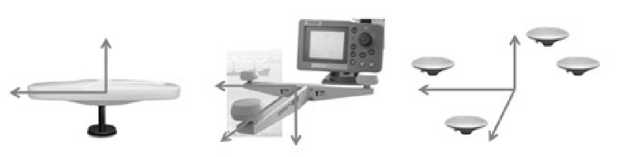
Fig. 1. Measuring axes of two, three and four antennas of ANR
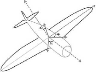
Fig. 2. Initial alignment of ANR
The measuring results of ANR are averaged within the given time interval and the corrections to the values of attitude orientation angles are calculated. Depending on normalized values of ANR bias time interval of the ANR measuring results averaging differs from several minutes to several hours. It is explained by the fact that ANR measuring results contain slowly changing error component of prior unknown period associated with multipath NS signals propagation.
II. Problem definition
For ANR with the error (according to probability level 0,95) of attitude orientation measuring by antenna system 3' for course angle and 4' for roll and pitch angles (for the distance between antenna modules of ANR antenna system not more than 2 m) the averaging interval of the results measuring amounts to 10 h, for ANR with the error (according to probability level 0,95) of attitude orientation measuring by antenna system 6' for course angle and 8' for roll and pitch angles (for the distance between antenna modules of ANR antenna system not more than 2 m) the averaging interval of the results measuring amounts to 5 h.
It is better to reduce the time of initial alignments in case conducting ANR initial alignments on site for the large amount of equipment. This fact is explained by the analysis of ANR measurements for the presence in the measured values a slowly varying component of the error as well as the period determination of a slowly varying component of the error.
III. Theory
The analysis of the presence in the measured values a slowly varying component of the error is performed by comparing of the average values of measured parts of the sample according to Student`s t -criterion. The algorithm step (minimum number of measurements) is prior determined for any ν ≤ 1ʹ, calculated with Formula (1):
v i = ( max (м l i - ^ M l i ) - min ( m l i - £ M l i )) , (1)
where Mli – arithmetic mean of i-sample part with length l.
Fig. 3 describes the calculation of an algorithm step for one of ANR modifications.
As one can see from Fig. 3 the algorithm step for pitch and roll angles equals to 2000 s, for course angle – 1000 s.
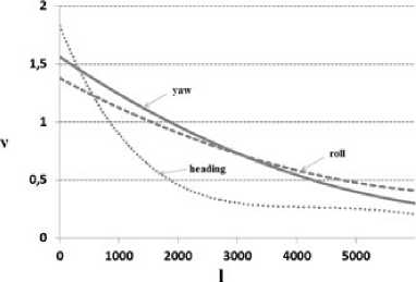
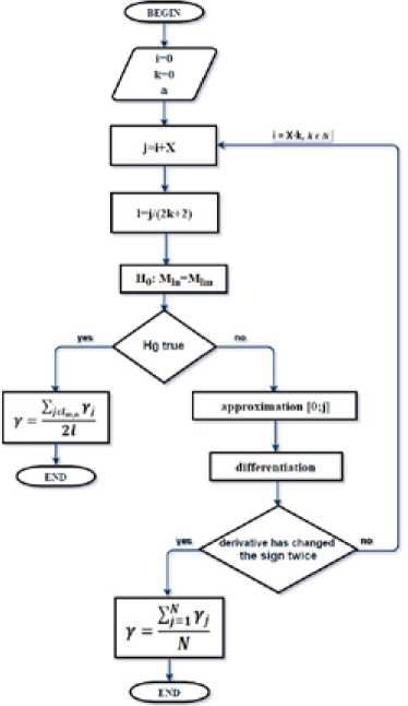
Fig. 4. Flow chart of ANR initial alignment algorithm
The period of the slowly varying component of the error is determined by the analysis of a derivative of measured ANR angle values as within the period of the slowly varying component of the error the derivative of input data changes its sign two times.
Flow chart of the developed algorithm of initial alignment is represented in Fig. 4.
In Fig. 4:
-
α – type 1 error probability (prior specified);
-
X – algorithm step (minimum number of attitude angle measurements);
-
H 0 – hypothesis on equality of two samples parts each with l length;
l = X/2;
-
M – mean value of samples;
-
n, m – sample order number;
-
N – number of measurements of an angle between two derivative symbol changing;
-
γ – attitude angle value under determination.
IV. Experimental results
The developed algorithm of ANR initial alignment was tested in the course of initial alignment of ANR measuring axes relative to construction axes of the object on site. The results of approbation are represented in Table 1.
Table 1. The results of the developed method approbation
|
№ |
Real angle value, degree |
Measured angle value, degree |
The difference of systematic corrections to measured angle value obtained by existing and by developed methods |
Time of measuring by existing method, s |
Time of measuring by developed method, s |
Reduced measuring time |
|
|
by existing method |
by developed method |
||||||
|
Course angle |
|||||||
|
1 |
157,3521 |
172,0357 |
172,0426 |
-0,417 |
1800 |
4000 |
By 4,5 times |
|
2 |
157,3527 |
172,0331 |
172,0426 |
-0,5735 |
1800 |
4000 |
By 4,5 times |
|
3 |
263,0027 |
262,9794 |
262,9621 |
1,0395 |
1800 |
4000 |
By 4,5 times |
|
Roll angle |
|||||||
|
1 |
-0,6603 |
-0,7925 |
-0,8132 |
1,2386 |
1800 |
8000 |
By 2,2 times |
|
2 |
-0,6583 |
-0,8097 |
-0,8247 |
0,9033 |
1800 |
8000 |
By 2,2 times |
|
3 |
-0,0811 |
-0,2386 |
-0,2425 |
0,2381 |
1800 |
8000 |
By 2,2 times |
|
Pitch angle |
|||||||
|
1 |
-0,2603 |
0,1674 |
0,1808 |
-0,8076 |
1800 |
3000 |
By 6 times |
|
2 |
-0,2576 |
0,1638 |
0,1808 |
-1,0224 |
1800 |
3000 |
By 6 times |
|
3 |
-0,2449 |
0,8919 |
0,8937 |
-0,1099 |
1800 |
6000 |
By 3 times |
V. Discussion of results
According to Table 1 there was a series of three experiments of ANR initial alignments on the object on site each experiment 5 h long (the demands of the existing ANR initial alignment method), the time of initial alignment performed by the developed method was reduced from 2,2 times to 6 times. Moreover the difference between systematic corrections and measured attitude angles values does not exceed 20% of ANR bias.
VI. Conclusion
Thus, in the course of performed researches the new method of defining the systematic corrections for ANR attitude angles measurement with the initial alignments on the customer object. ANR initial alignment carried out by the developed method is not less than 50% faster than by existing methods.
References Ensuring the required accuracy of initial alignment of GNSS attitude navigation receivers on user equipment
- Alirshin B., Veremeenko K., Chernomorsky A. Orientation and navigation of mobile objects: modern information technologies. М.: FIZMATLIT, 2006, 424 p..
- Emelyancev G., Dranitsyna E., Blazhnov B. Test bed calibration of FOG-based strapdown inertial measurement unit. Scientific and technical journal "Gyroskopiya i Navigatsiya", 2012, 3(78), 55-63.
- Mohammed El-Diasty, Spiros Pagiatakis. Calibration and Stochastic Modelling of Inertial Navigation Sensor Errors, Journal of Global Positioning Systems, 2008, 7 (2), 170-182.
- Parusnikov N. The task of calibrating a non-carded inertial navigation system at orthogonal frame. Proceedings of the Russian Academy of Sciences. Mechanics of solids. 2009, (4), 3-6.
- Alirshin B., Antonov D., Veremeenko K., Zharkov M. Strongly coupled multi-antenna integrated inertial-satellite navigation system, Electronic Journal «Trudy MAI», 54, 14-17.
- Borsoev V., Grebennikov А., Desyatov А. Integration GLONASS/GPS attitude reference receivers with INS on aircrafts. Scientific Bulletin of MSTUCA. Radiophysics and Radio Engineering Series, 2009, 139, 91-95.
- Shebshaevich V., Dmitriev P., Ivancevich N. and other; edited by V. Shebshaevich. Network satellite radio navigation systems. 2-nd edition, Мocow, Radio and svyaz, 1993, 408 p..
