ERPWS: An Energy Efficient Routing Protocol for Conductive Sensor based Water Level Monitoring and Control System using Zigbee and 74HC14 Inverter

Автор: Saima Maqbool, Nidhi Chandra, Shivraj Dagadi
Журнал: International Journal of Modern Education and Computer Science (IJMECS) @ijmecs
Статья в выпуске: 6 vol.5, 2013 года.
Бесплатный доступ
In this paper we have shown how to use conductive sensor, Zigbee and 74HC14 Inverter to monitor the water level and to control the working of pump. This project is designed to automatically fill the over head tank when it gets empty and monitor the water level in it. The motor is switched ON when the water level in the overhead tank drops below a pre fixed low level (on point) and puts off the motor when water level rises up to pre fixed high level (off point).The motor is also switched off during the following conditions: when the sump water is exhausted before filling overhead tank, pump running dry, mains voltage fluctuations. We also introduce an energy efficient routing protocol for Wireless Sensor Networks (ERPWS) for Conductive Sensor based Water Level Monitoring and Control System using Zigbee (XBEE 802.15.4) in terms of energy consumptions, the packet loss ratio, network lifetime and the average delivery delay. The XBEE used here is XBEE Pro Series 1(XBP24-AWI-001) and IC used is 74HC14 Hex Inverting Schmitt trigger. Simulation results have been obtained by using NS2 simulator. The evaluation results show that the energy consumption of routing using ERPWS is significantly lower than LEACH and traditional routing protocols.
Wireless sensor networks, Water Level, Xbee, Routing Protocol, Energy, Conductive Sensor, 74HC14 Inverter, NS2 Simulator
Короткий адрес: https://sciup.org/15014557
IDR: 15014557
Текст научной статьи ERPWS: An Energy Efficient Routing Protocol for Conductive Sensor based Water Level Monitoring and Control System using Zigbee and 74HC14 Inverter
Published Online July 2013 in MECS DOI: 10.5815/ijmecs.2013.06.05
Wireless Sensor Networks (WSNs) [1] represent an inventive technology used for monitoring specific environments due to the ease of installation, availability as well as maintenance, and the affordable price of sensors. Water is commonly used for irrigation, industry, household usages and electricity. Therefore, efficient use and monitoring of water are potential constraint for water management system. Though a few WSN-based water level monitoring and control applications have been introduced recently, they are costly and use complicated architecture. With the increase of life and industrial waste water, it is necessary to monitor and control water level.
Thus, we introduce a simple WSN-based Water level Monitoring and Control System which uses Conductive Sensor, XBEE pro series 1, and 74HC14 Hex Inverting Schmitt Trigger. The proposed method helps to have real-time readings about the water level. The primary contribution of this work is the introduction of the Conductive sensor which is a water level sensor used to monitor and control water level.
The XBEE wireless radio RF module are a quick, inexpensive, and easy way to implement a wireless serial interface between two devices. They are practically a drop in replacement for a TTL-level serial cable. They have a low (~ 50mA) current consumption, and long range (rated at 300ft line of sight). Series 1 XBEE devices cannot talk to Series 2 (or series 2.5 devices).Connecting to the XBEE devices is quite easy; however, they are 3.3V devices. These devices use the IEEE 802.15.4 networking protocol for fast point-to-multipoint or peer-to-peer networking. They have the property of low power, easy network, and free bands at frequency 2.4GHz. XBee also has strong antiinterference ability [2].
The 74HC14 is a high-speed Si-gate CMOS device and is pin compatible with Low-power Schottky TTL (LSTTL). It is specified in compliance with JEDEC standard No. 7A.The 74HC14 provides six inverting buffers with Schmitt-trigger action. It is capable of translating slowly changing input signals into sharply defined, jitter-free output signals [3].
In this paper, water level monitoring and control system based on XBEE 802.15.4 wireless sensor is designed to monitor and control the water level effectively. Water controlling system implementation makes potential significance in home applications. Besides this, water level control system is widely used for monitoring of liquid levels, reservoirs, silos, and dams etc. This system provides visual multi level as well as continuous level indication. In our proposed system alarms at desired levels are generated and pumps are controlled automatically based on user’s requirements. The system is also supported by GSM modem to send the measured data via SMS (Short Message Service) into two specific clients’ phone numbers that have previously been inputted into the system.
Moreover, we introduce a simple Routing Protocol of Water Sensor network (ERPWS) that is effective for WSN-based Water Level Monitoring and Control System as well as energy efficient.
Simulation results show that the ERPWS protocol has longer network lifetime and thus, works several years without replacing the batteries.
The rest of the paper has been categorized as follows: Section II contains related work, Section III consists of the proposed system, Section IV presents detailed hardware design, Section V involves the system implementation, and Section VI includes routing protocol and section VII includes conclusion.
-
II. RELATED WORK
In this section we have presented a number of previous wireless sensor network based water monitoring applications.
An efficient Clustering Protocol for Water Sensor network (CPWS) for the proposed fish pond monitoring was designed that monitors fish ponds uses RGB (RGB: Red, Green and Blue colors) sensors. This system helps the fish farmers to have real-time readings about the water quality of their pond as well as water level [4].
Microcontroller Based Automated Water Level Sensing and Controlling system was designed to investigate the microcontroller based water level sensing and controlling in a wired and wireless environment. This system would help in reducing the home power consumption and as well as water overflow. Furthermore, it indicates the amount of water in the tank that supports Global Water types including satellite data transmission systems for remote water monitoring system. This system proposed a web and cellular based monitoring service protocol would determine and senses water level globally [5].
Polluted Water Monitoring Based on Wireless Sensor system was designed that collects data and transfer to the host computer using wireless sensor network. The host computer displays that data in the form of values and curves, stores that data in database, queries the history data, and provides an alarm signal when polluted level exceeds the standard value. This system has designed coordinator node, router node and end device node based on ZigBee technology. With the help of these three kinds of node, polluted water monitoring system on Wireless Sensor performed well. In this system user interface is programmed with configuration software MCGS [6].
According to the status of water level monitoring of inland river Development and Application of Mobile Water Level Monitoring Based on Multi-sensor Integration was designed that presents and designs a multi-sensor integrated dynamic system for mobile water level measurement, which is based on GPS (global positioning system), CORS (continuous operational reference system) GPRS (general packet radio service), PDA (personal digital assistant) technology as well as a post processing platform. This system has been used for an actual experiment. The results that have been shown have high flexibility and stability [7].
The Automatic Monitoring Device of Ground Water Level Based on Embedded Systems was designed. It is composed to a take-off and landing control circuit by a water level monitor, a comparator IC and 89C51 singlechip. The automatic recording devices combined with dynamic software have achieved a dynamic real-time, accurate, continuous convenient monitoring of the groundwater. Through effective points, the system achieved dynamic effective monitoring of the groundwater in region, and provides strong data support for sustainable use of regional water resources [8].
Water-Level Monitor for Borewell and Water Tank Based on GSM was designed that monitors the tank water level and bore well water level remotely by using GSM technology. This GSM based system automatically gives a call to the owner mobile phone, when the water level in the bore well rises to the threshold level or drops below threshold level for pumping. The user also remotely switches on or off the pump motor by sending a SMS from his mobile phone. This system is reliable, simple, portable and affordable. High precision water level sensor is used to identify the reference water level to activate and deactivate the motor and system properly by interfacing the sensor devices into the well defined embedded system [9].
An Autonomous and Adaptable Wireless Device for Flood Monitoring was designed that trigger an alarm if flood situation comes. This system used varying number of instances to monitor flood based on the characteristics of the location to be monitored. A box with the sensor can move up and down to read the stationary magnets. The sensor is also responsible to know the direction of the movement for water level readings. To ensure the communication with the base station (BS) the sensor box is always kept above the water level using a floater [10].
Wireless Sensor Network Application for Cost Effective Environmental Monitoring was designed that collects data from water sources e.g., pH level, temperature, wind speed to measure water quality and amount of dissolved oxygen. The authors used MDA300 data acquisition boards, Crossbow Technology's mica2 motes, and external sensors to collect and store the data for analysis. They compared this system with a wired system (DATALOGGER CR3000), and proved that WSN performed perfectly [11].
Due to increasing number of WSN applications, designing energy efficient routing protocols for WSN is very important. Among existing routing protocols of WSN, The Depth-Based Multi-hop Routing Protocol for Underwater Sensor Network [12] was proposed in which nodes decide whether a packet to be forwarded or not based on the previous node and the depth of a node which is a greedy approach. However, every node must be provided with a depth sensor in Depth Based Routing that increases energy consumptions and deployment cost. Depth Based Routing also increases the routing complexity.
In LEAR (Location Based Energy-Efficient Reliable Routing Protocol) [13] each node sends its location information to its neighbors. The location information that has been used in LEAR algorithm could be extracted from Global Positioning System. Each node in this geographic area constructs its routing table based on the distances to its neighbors. As in our protocol ERPWS, each node makes a decision about forwarding the message to the selected candidate.
Our protocol ERPWS is designed to reduce the number of packets transferring in the network, and also reduces the needed energy consumption. The protocol has been evaluated using NS2 Simulator [14]. The results show that the number of reduced packets is considerable.
-
III. PROPOSED SYSTEM
In this section we have explained our system architecture, design and working mechanism of our proposed system (test bed).
-
A) System architecture
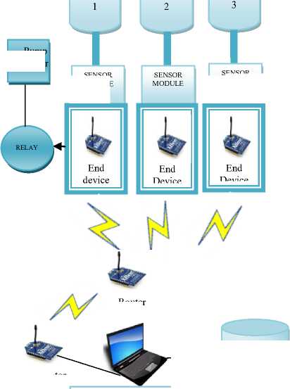
The architecture of the proposed Water Level Monitoring and Control System that monitors the level of water and controls the working of pump automatically is presented in fig.1.

MAIN TANK
MAIN TANK
MAIN
TANK
RELAY
Coordinator
PC displaying the information
Figure1. Architecture of Water level Monitoring and Control System
Pump Motor
SENSOR
MODULE
SENSOR MODULE
Router
Database

The Water Level Monitoring and Control System are designed as simple, low cost, energy efficient, and sustainable. The main design challenges of the proposed water monitoring system are to ensure that the sensors are always on the surface of the water and able to work in unusual circumstances like rain.
To monitor the water level, we placed our water level sensors on our tanks that consist of five pins of different colors Black (P1), Brown (P2), Red (P3), Orange (P4), and Yellow (P5). The level monitoring of the system works as follows. The Black pin P1 is given +5v and when it touches the water all other wires which touch the water get electric connection using water conductivity. The Brown pin P2 senses the 1nd highest level of water, similarly P3 senses 2rd and P04 senses 3th level of water. Yellow pin P5senses the level of water at the highest level (e.g., enough water is in the tank). These data will be transmitted to the PC through Xbee to perform the required action (e.g., ON/OFF water pump). At the same time information can be sent wirelessly to the phone numbers inputted in our system. We can also deploy pH sensors that monitor water quality (e.g., pH level, oxygen level) on the water surface and floating. These sensors collect the pH level, and the level of the dissolved oxygen, and direct the data to the Coordinator through router nodes. In the proposed system, a database is maintained to store the collected data for future use to build a water expert system.
-
B) Working Mechanism
The proposed system architecture includes several components: sensor, end devices, router, coordinator, PC and a database. Sensor nodes performs the specific task, sensing and transmitting data to the coordinator via router according to the specific rule set by users or network implementers. The router is a device that collects data from end devices which in turn from sensors, performs data aggregation and sends the aggregated data to coordinator.
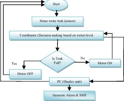
Figure2. Flow chart of Water Level Monitoring and Control System
Data aggregation is used to ignore the unwanted part of the data and forwards the necessary data to Coordinator and also to reduce the number of redundant data. Thus, energy efficiency of the WSN is achieved by reducing number of data transmissions. SMS services are not mandatory but can be used to monitor the WSN remotely. As mentioned earlier a database is used to log data sent from sensing nodes, and coordinator.
These data are used to build a water expert system through a long term monitoring and analysis. Fig. 2 explains the data flow from WSN to the end users.
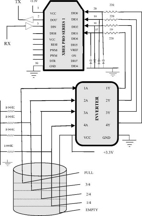
inducting rubber and steel that is connected with + 5V. Due to water conductivity 220Ω resistance has been used. The basic operation is, when one wire of the sensor is drawn into water, steel of Black wire becomes connected due to water conductivity. Then gets +5V signal which is connected with input of the inverter. The output of inverter is given as the input of Xbee (End device) which sends that information to coordinator connected to PC, acts as user display unit.
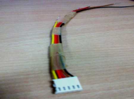
Figure3. Water Level Sensor
B) 74HC14 Inverter
We have used 74HC14 Hex Inverting Schmitt trigger that has 14 pins (1-14).The 74HC14 provide six inverting buffers with Schmitt trigger action capable of transforming slowly changing input signals to jitter free output signals. Symbols: 1A-6A with pin numbers 1, 3, 5, 9, 11 and 13 are data input pins. 1Y-6Y with pin numbers 2, 4, 6, 8, 10 and 12 are data output pins. Pin number 7 is ground (0 V) and pin 14 is supply voltage (VCC). Pin diagram of inverter 74HC14 has been shown in fig 4. In our system we have used 4 input-output pins. Input to inverter is sensor input and then output of inverter is given to Xbee. Logic diagram of inverter with Xbee and sensor module has been shown in Fig 5.
-
IV. Detailed HARDWARE DESIGN
In this section we have explained every component used in our proposed system, operation description and complete circuit diagram. For implement this design we have used a PC, water level sensor, 74HC14 inverter, Xbee Pro Series 1, water tank, a reserve tank, water pump. Water pump is controlled using water level sensor. Five homemade water level sensors are used to detect the water level. Inverted sensor data used to pass as the input of Xbee. We used C# programming software to display that information on PC.
-
A) Water Level Sensor
Water level sensor consists of five sensors; all five sensors are placed inside water tanks. Moreover, sensors are composed of wires with different colors Black, Brown, Red, Orange and Yellow. These wires have
1Y
2A
2Y
3A
3Y

1A


GND


VCC
6A
6Y
5A
5Y
4A
4Y
Figure4. Pin diagram of 74HC14 inverter


Xbee
Inverter
Sensor
Module

Figure5. Logic diagram
-
C) Xbee pro series 1
In our proposed system we have used Xbee pro series 1 which is the very popular 2.4GHZ Xbee XBP24-AWI-001 module from Digi. This series have the same pinout and command set of the basic series with an output power of 60mW and allow a very reliable and simple communication between computers, microcontrollers, systems with a serial port. Xbee has 20 pins as shown in fig 6. Pin 1 is connected to VCC; pin 10 is connected to ground. It has 13 I/O pins out of which we have used 4 pins for input from inverter as shown in fig 6. We have configured these 4 pins by using X-CTU software as shown in fig 7.In our system we have used three types of nodes: coordinator node, router node and end device node. Coordinator is responsible for the receiving data from router or end device nodes in its network. The collected data are then transferred to host computer through USB serial port communication. Router node can realize the joining of new terminal nodes and router nodes. Then the router node can collect data directly or receive data from other router nodes and end device nodes. The router collected data are then transferred to the coordinator. XBee end device node collects data, and transfer data to XBee router or coordinator node which it joined.
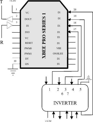
Figure 6. Block diagram of Xbee with inverter
-
i) XBEE Specifications
The main features of Xbee Pro are 2.4GHz working frequency, 100dBm receiver sensitivity, 2.8V-3.4V supply voltage range and low current consumption for 55mA in receiving mode, 250mA in transmit mode, 0.9µA in sleep mode, 0.6µA in standby mode, so it can even be supplied with batteries.
TABLE I
Specifications of the Xbee/Xbee Pro RF modules [2]
|
Specification |
Xbee |
Xbee Pro |
|
Indoor/Urban Range |
100 ft (30 m) |
300 ft. (90 m), up to 200 ft (60 m) |
|
Transmit Power Output |
1mW |
63mW |
|
RF Data Rate |
250,000 bps |
250,000 bps |
|
Serial Interface Data Rate |
1200 bps -250 kbps |
1200 bps - 250 kbps |
|
Supply Voltage |
2.8 – 3.4 V |
2.8 – 3.4 V |
|
Operating Frequency |
ISM 2.4 GHz |
ISM 2.4 GHz |
|
Number of Channels |
16 Direct Sequence Channels |
12 Direct Sequence Channels |
|
Receiver Sensitivity |
-92 dBm (1% packet error rate) |
-100 dBm (1% packet error rate) |
|
Transmit Current |
45mA (@ 3.3 V) |
250mA(@3.3V) |
|
Idle / Receive Current |
50mA (@ 3.3 V) |
55mA (@ 3.3 V) |
With reference to the design, XBee basis module is shown as Figure 6 that can realize the chip working and wireless data transmission. Xbee has resistors used to set accurate bias current for the 32 MHz crystal oscillator and capacitors, inductors together with a PCB microstrip transmission line will match the RF input/output to 50 Ω . Some of the specifications of Xbee and Xbee Pro are listed in table I
-
ii) XBEE Configuration
An XBEE USB Explorer can be used to connect an XBEE directly to your PC. It is a compact circuit board that already has a 3.3V regulator, plus a USB connection to communicate with your computer. It draws power directly from the serial port. Simply plug it into a USB port (The XBEE Explorer is the red circuit board shown in the picture below).The parts required for configuring Xbee are XBEE Pro series, XBEE Explorer and XBEE Breakout board.
To set up XBee, install the X-CTU tool, which is a tool that configures your XBee with whatever settings we need. And begin configuring your XBees. Since we are constructing a point-to-point network, meaning two devices are going to communicate together, one of the devices must be a Coordinator (all XBee networks require a Coordinator) and the other must be a Router (an 'endpoint' device). Plug XBee into your XBee explorer and USB Dongle, and plug it into your computer. Once connected, open the X-CTU configuration tool. The tool will list all serial ports on your computer. Then selected COM8, which is the Virtual COM Port created by my currently connected XBee USB Dongle. Connect XBee by pressing the Test / Query button. X-CTU will attempt to connect to your XBee and let you know its current firmware. If X-CTU cannot find legitimate XBee, or have an XBee from another supplier that has not come programmed we will see this pop-up: If XBee correctly reports its firmware carry on, or have selected the correct Comport. Now we are ready to program our XBee. The first XBee is going to be our Coordinator module, basically the boss of the private area network (PAN) we are going to create. To program an XBee we need to upload new firmware to it. To do this, navigate to the Modem Configuration tab in X-CTU and choose the following configuration.
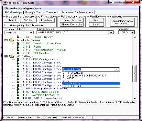
Figure7. Configuration of Xbee
Click Write and X-CTU will attempt to program you XBee, this should take 30 seconds or so, you may be asked to press the RESET button on your USB Dongle. When your XBee has been successfully programmed, press the Read button to retrieve the configuration of the device. The screen shot of X-CTU terminal has been shown in fig 7.
Write down the SH - Source Address High and SL -Source Address Low used in the next step. The Coordinator node is now complete(mark this XBee as Coordinator) and now program the next XBee by using the same procedure and then in Modem Configuration tab program the node as a End Device. Select the same configuration as listed in table 2 and press Write, this will take another 30seconds. Once this XBee is programmed, press Read to get the configuration. To tell this XBee which Coordinator to connect to, we need to give it the address. We do that by setting the DH - Destination Address High and DL –
Destination Address Low with the serial number we took from the Coordinator. Put this information in and then press Write to write this new configuration to the
XBee. The configuration settings of remote and base Xbee has been listed in table II.
TABLE II. Configuration settings
|
Remote Configuration |
Base Configuration |
|
DL = 0x4567 MY = 0x1234 D0, D1, D2, D3 = 3 IR = 0xFF IT = 0x2 IC = 0x18 |
DL = 0x5678 MY = 0x1234 D0,D1, D2, D3 = 4 IU = 1 IA = 0x5678 (or 0xFFFF) T3 = 0x64 T4 = 0x64 |
Fig 8 shows the status of packet received from end device to coordinator. The packet starts with 7E which is start delimiter; the next two bytes of packet are length bytes which in our case are 00 0A .The 4th byte which in our packet is 83 (API id) denotes the API specification for 16 bit. The 5th and 6th bytes are address bytes which in our case are 56 78. The next byte is RSSI value bytes which in our packet is 27.
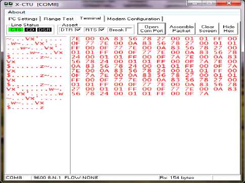
Figure8. Status of packet received from end device to coordinator
The 8th byte is 00 which is option byte; the 9th byte is 01 which is sample quantity byte. The 10th and 11th byte 01 FF represents channel indicator. 12th and 13th bytes 00 01 are sample data where 1 represents high and 0 represents low.
-
D) Operation Description and Complete Circuit
Diagram
To implement the system we have used necessary parts such as Xbee Pro series 1, 74HC14 inverter, LED, PC, water tank, water level sensor, water pump and some resistors having resistance 220ohm.
Water Tank
Figure9. Complete Circuit Diagram
sends this data to another Xbee called coordinator and the information (Different water levels) can be displayed on PC.
TABLE III Experimental Results of Water Level Monitoring and Control using LED
|
Input from Water Sensor |
OUTPUT |
|||||
|
Water Tank |
LED 1 |
LED 2 |
LED 3 |
LED 4 |
MOTO R |
Tan k |
|
0000 |
ON |
ON |
ON |
ON |
ON |
Em pty |
|
1000 |
OFF |
ON |
ON |
ON |
No OP |
1/4 |
|
1100 |
OFF |
OFF |
ON |
ON |
No OP |
2/4 |
|
1110 |
OFF |
OFF |
OFF |
ON |
No OP |
3/4 |
|
1111 |
OFF |
OFF |
OFF |
OFF |
OFF |
FU LL |
-
V. SYSTEM IMPLEMENTATION
This section consists of software and hardware implementation of our system.
-
A) Software Implementation
The program we used to control the whole process has been written in C sharp language. The screen shots have been shown in Fig. 10 and fig. 11. In fig.10 it has been shown that tank 1 is filled with two levels, tank 2 with one level and tank 3 is empty. And in fig. 11 it has been shown that tank 1 is full, tank 2 is filled with two levels and tank 3 with only one level.
The complete circuit diagram is shown in Fig. 9. DIO0, DIO1, DIO2 and DIO3 pins of Xbee are used to get inverted output from the water source. If four pins DIO0, DIO1, DIO2 and DIO3 gets ground signal (0v) that means there is no water in the water tank. So, all LEDs should be ON. And if we found pin no DIO0 senses positive signal (+5v) then we can tell that water tank is full of water. So, when water tank is empty then water pump should becomes on and all LED light becomes ON. If pin no DIO3 gets positive signal (+5v) and other three gets ground signal (0v) that means water tank has 1/4 th water. For this reason water pump remains on and the first LED should be OFF now; other three LEDs are still remaining ON. If the four pins DIO0, DIO1, DIO2 and DIO3 get positive signal (+5v) that means water tank is now full of water. For this reason the water pump should be off now and all the LEDs should be OFF. Notice that we used these LEDs for test only. When the water is decreasing from the tank by home use, the display LED should start to become ON one after another from the top to bottom. If all the LEDs becomes ON that means the tank becomes empty again and the water pump should becomes automatically ON again exactly after the last LED becomes ON. These operations should automatically perform as a cycle. All experimental results are listed in table 3. The Xbee which takes inverted sensor data is an end device and
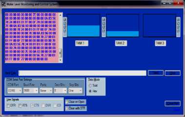
Figure10. Screenshot showing the status of Tank 1, Tank 2 and tank 3
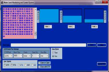
Figure11. Screenshot showing the status of tank 1, tank 2 and tank 3
-
B) Hardware Implementation
This part consists of some pictures of our proposed system. In this system we have used 3 tanks, various XBees as end devices, router and coordinator, 3 water level sensors, 3 74HC14 inverters, buzzer, resistors, leds and Nokia phone as GSN modem. The working of our proposed system has been explained already in section 3. Fig.12, fig. 13, fig. 14, fig. 15, fig.16 and fig.17 shows the pictures of our system Monitoring and Control of Water Systems
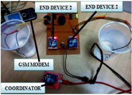
Figure12. Picture of Water Level Monitoring and Control System (A)
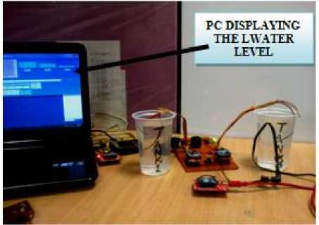
Figure13. Picture of Water Level Monitoring and Control System (B)
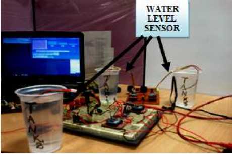
Figure14. Picture of Water Level Monitoring and Control System (C)
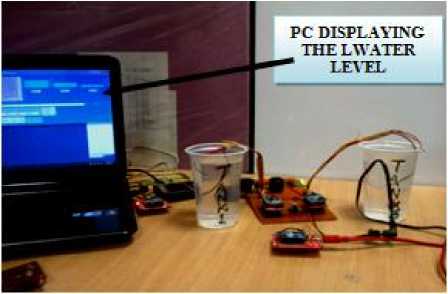
Figure15. Picture of Water Level Monitoring and Control System (D)
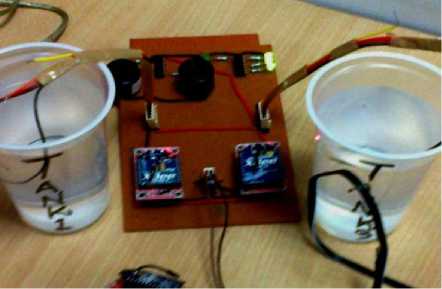
Figure16. Picture of Water Level Monitoring and Control System (E)
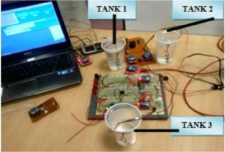
Figure17. Picture of Water Level Monitoring and Control System (F)
-
VI. ROUTING PROTOCOL
WSN nodes are energy constrained, and therefore energy-efficient protocol design is a big issue. So we introduce a simple Energy Efficient Routing Protocol for Wireless Sensor Networks (ERPWS) for Water Level Monitoring that exhibit large energy savings compared to other routing protocols and achieve quasi-optimal energy consumption.
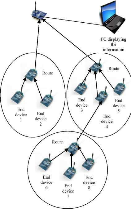
Generally housing colonies consists of a number of tanks to supply water. These tanks are close to each other. Fig. 12 shows the network topology with 12 Zigbee nodes (1 coordinator, 3 router and 8 end device nodes) which participated in the performance evaluation. Initially, base station (BS) randomly selects a node as router on each tank. BS also selects the data sensing and/or transmission interval and informs each node through router. Routers select only a few end device XBees as active based on the sensing range and the monitoring area. Other end device XBees remain in sleep mode by turning their radio off. Router Xbee select the most residual energy nodes as active which are reselected after a certain number of rounds (i.e., data sensing) to balance the energy dissipations of individual sensors and network. After the specified sensing interval, active end device XBees wake-up and transmit data to router XBee which will aggregate data and sends to BS if BS is within the communication range of router XBee. Otherwise, a router XBee forms a path to BS through other Routers and gateway nodes. During the initial network setup, a Router decides whether it can directly transmit data to BS or need to select gateway nodes and a data transmission path to transmit data to BS.
Coordinator
Route
Route
Route
End device 2
PC displaying the information
End device 5 End device
End device 1
End device 6
End device 7
End device 8
End device 3
Figure12. Network Topology of ERPWS protocol with three clusters
We conduct extensive simulations in NS2 simulator to evaluate the performances when using our ERPWS (Energy Efficient Routing for Wireless Sensor Networks). The simulation results reported here is based on the tree topology and dataset. There are 12 nodes in the tree topology. The simulation parameters are listed in table IV.
TABLE IV Simulation Parameters
|
Parameters |
Values |
|
Number of nodes |
12 |
|
Initial Energy |
100 joules |
|
Simulation Length |
10.0s |
|
Network area |
1000m x 1000m |
|
Routing Protocol |
AODV |
|
Pause Time |
10.0s |
|
Communication Range |
550m |
|
Bandwidth |
1Mbps |
|
Dataflow time |
1.0s |
|
Delay |
0.01s |
|
Hop Count |
4 |
There are a total of 444 source-destination pairs in the tree topology. For each source-destination pair we run 20 simulations with different random seeds and the averages of these 20 simulation runs are reported in the discussion below.
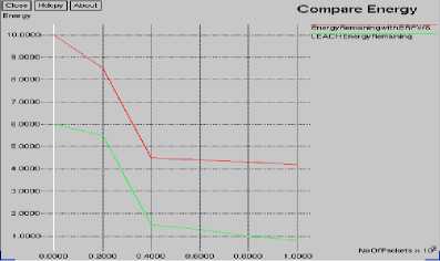
Figure13. Comparison of Energy remaining between our proposed protocol and LEACH
Compare PackctDrop
LEACH Pack Drop
PackdropwithERPWS
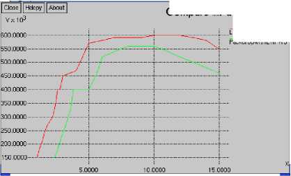
Figure14. Comparison of Packet Drop between our proposed protocol and LEACH
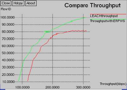
Figure 15. Comparison of Throughput between our proposed protocol and LEACH
We now use our protocol and compare the performances for each source-destination pair. We analysed energy, throughput and Packet Drop for the flow taken. We compared the existing protocols with our own protocol for delay, throughput, packet drop, energy consumption, obtained the various graphs shown below. In Fig 13 it has been shown that energy consumption in our protocol is less than the existing protocols e.g. LEACH protocol. The experiment was running 7 seconds of time. This is because the proposed ERPWS routing protocol selects a few active nodes on each tank (or cluster) that transmit data to their routers whereas, in LEACH all member nodes of a cluster send data to router using TDMA scheme. In fig 14 it has been shown that Packet Drop of our protocol is less than existing protocol. This is because sensors in the ERPWS routing protocol do not require frequent data sensing for Water monitoring system whereas this is not the case for LEACH routing protocol. In fig 15 it has been shown that throughput of our protocol is more than existing protocol.
-
VII. CONCLUSION
Water is one of the most important basic needs for all living beings on earth. If there was no water there would be no life on earth. But unfortunately a huge amount of water is being wasted by uncontrolled use. Some automated water level monitoring system is also offered so far but most of the method has still some shortness. We tried to overcome these problems and implemented an efficient automated water level monitoring and controlling system. Our motive of this research work was to establish a reliable, flexible, economical and easy configurable system which can solve our water losing problem. We have been used a low cost sensor, Xbee pro series 1 and 74HC14 in this system which is the key point to reduce cost. Moreover, we introduce an energy efficient routing protocol (ERPWS) for this WSN-based Water level monitoring system which periodically transmits data over a short distant base station. The proposed framework can be used as a possible solution for monitoring water quality.
Acknowledgment
This work is an outcome of rigorous work done under the supervision and guidance of my research guides. I like to pay my sincere thanks to them, for their kind support and cooperation. I am thankful to Centre for the Development of Advanced Computing (CDAC), Noida for their support in the proposed system (ERPWS: An Energy Efficient Routing Protocol for Conductive Sensor based Water Level Monitoring and Control System using Zigbee and 74HC14 Inverter). I am also thankful to Amity University, Noida for their encouragement and guidance to publish this paper.
Список литературы ERPWS: An Energy Efficient Routing Protocol for Conductive Sensor based Water Level Monitoring and Control System using Zigbee and 74HC14 Inverter
- Jun Zheng and Abbas Jamalipour, “Introduction to Wireless Sensor Networks”, Book: Wireless Sensor Networks: A Networking Perspective, Wiley-IEEE Press, 2009.
- Datasheet XBee?/XBee-PRO? OEM RF Modules. “Product Manual v1.xAx - 802.15.4 Protocol”, For OEM RF Module Part Numbers: XB24-...-001, XBP24-...-001.
- Datasheet 74HC14; 74HCT14. Hex inverting Schmitt trigger, Rev. 6 — 19 September 2012.
- Nidal Nasser1, ANK Zaman, Lutful Karim and Nargis Khan, “CPWS: An Efficient Routing Protocol for RGB”, IEEE 8th International Conference on Wireless and Mobile Computing, Networking and Communications (WiMob), 2012.
- S. M. Khaled Reza, Shah Ahsanuzzaman Md. Tariq, S.M. Mohsin Reza, “Microcontroller Based Automated Water Level Sensing and Controlling: Design and Implementation Issue”, Proceedings of the World Congress on Engineering and Computer Science 2010 Vol I (WCECS), October 20-22, 2010
- CHEN Chen, XU Jun-ming, GAO Hui-fang,“Polluted Water Monitoring Based on Wireless Sensor”, IEEE, 2012.
- Hongmei Zhang, Weiliang Tao Ming Cao, “Development and Application of Mobile Water Level Monitoring Based on Multi-sensor Integration”, IEEE International Conference on Electrical and Control Engineering, 2010.
- Xiao Ying, Zhu Bing, Liu Yong, and Peng Xuange, “The Automatic Monitoring Device of Ground water Level Based on Embedded Systems”, In the Proceedings of the 2009 International Symposium on Information Processing (ISIP’09) , August 21-23, 2009, pp. 241-244.
- R.Ramani, S.Selvaraju, S.Valarmathy, R.Thangam, B.Rajasekaran, “Water-Level Monitor for Borewell and Water Tank Based on GSM”, In International Journal of Engineering Science and Technoloy (IJEST),Vol. 4 No.10 October 2012.
- Valerio Plessi, Filippo Bastianini, and Sahra Sedigh-Ali, “An Autonomous and Adaptable Wireless Device for Flood Monitoring”, In the Proceedings of the IEEE 30th Annual International Computer Software and Applications Conference (COMPSAC'06), 2006.
- Ruqayyah Mustafa, Jung H. Kim, John Kelly, Ro Le, JungHee Kim,“Wireless Sensor Network Application for Cost Effective Environmental Monitoring”, IEEE, 2009.
- Liu Guangzhong, Li Zhibin, “Depth-Based Multi-hop Routing Protocol for Underwater Sensor Network”.In 2nd International Conference on Industrial Mechatronics and Automation, IEEE, 2010.
- Rafe Alasem, Ahmed Reda, and Mahmud Mansour,” Location Based Energy Efficient Reliable Routing Protocol for Wireless Sensor Networks”.In ACM, World Scientific and Engineering Academy and Society (WSEAS), Pages 180-185, 2011.
- Teerawat Issariyakul, Ekram Hossain, “Introduction to Network Simulator NS2”. In Springer Science, Business Media, LLC, 2009.
