Errors in measuring the angular coordinate of extended targets by the monopulse method in the Fresnel zone of the linear antenna array

Author: Ragozin A.N., Darovskich S.N., Telezhkin V.F., Pletenkova A.D.
Section: Инфокоммуникационные технологии и системы
Article in issue: 2 т.20, 2020.
Free access
Introduction. The basic theoretical information on measuring systems in radar is presented, an analysis is performed to determine the errors of direction finders, and calculation expressions are found to determine the magnitude of the direction-finding errors by a single-pulse method in the Fresnel zone of a linear receiver antenna array caused by the combined action of the internal noise of the radio direction finder receiver and the angular noise of extended reflective interference. Purpose of the study. To consider the influence on the magnitude of the errors of direction finding together of the levels of the side lobes of both the differential and total directivity characteristics of the receiving antenna of the radio direction finder in the Fresnel zone. Materials and methods. Approaches for determining the magnitude of direction-finding errors are a generalization to the Fresnel zone of the known result of calculating the error during operation of a monopulse direction finder in the far zone of the receiving antenna. Results. The influence of the angular size and the distance size of a multi-point reflector on the magnitude of direction-finding errors by a single-pulse method in the Fresnel zone of a receiving linear antenna array of a radio angular system is investigated. Conclusion. Theoretical methods of measurement in radar are considered and it is shown that expanding the functionality to ensure high accuracy of measuring an information parameter will improve the accuracy of determining errors in direction finding systems.
Direction finder, monopulse method, the accuracy of direction-finding, angular resolution, receiving antenna, antenna array, fresnel zone, the directional characteristics of the antenna, internal noise, corner noise, measurement error
Short address: https://sciup.org/147233759
IDR: 147233759 | UDC: 621.396.96:621.336.75 | DOI: 10.14529/ctcr200207
Погрешности измерения угловой координаты протяженных целей моноимпульсным методом в зоне Френеля линейной антенной решетки
Введение. Изложены основные теоретические сведения о измерительных системах в радиолокации, проведен анализ для определения погрешностей радиопеленгаторов и найдены расчетные выражения для определения величины погрешностей пеленгования моноимпульсным методом в зоне Френеля приемной линейной антенной решетки, вызванных совместным воздействием внутреннего шума приемника радиопеленгатора и углового шума протяженной отражающей помехи. Цель исследования. Рассмотреть влияние на величину погрешностей пеленгования совместно уровней боковых лепестков как разностной, так и суммарной характеристиками направленности приемной антенны радиопеленгатора в зоне Френеля. Материалы и методы. Подходы для определения величины погрешностей пеленгования являются обобщением на зону Френеля известного результата расчета ошибки при работе моноимпульсного радиопеленгатора в дальней зоне приемной антенны. Результаты. Исследовано влияние углового размера и размера по дальности многоточечного отражателя на величину погрешностей пеленгования моноимпульсным методом в зоне Френеля приемной линейной антенной решетки радиоугломерной системы. Заключение. Рассмотрены теоретические методы измерения в радиолокации и показано, что расширение функциональных возможностей по обеспечению высокой точности измерения информационного параметра позволит повысить точность определения погрешностей в системах радиопеленгования.
Text of the scientific article Errors in measuring the angular coordinate of extended targets by the monopulse method in the Fresnel zone of the linear antenna array
The operation of the direction finder as part of a radio-angle measuring system is usually accompanied by interfering influences caused by re-reflected signals. In this case, the direction-finding radio source and interfering reflectors may be in the Fresnel zone of the receiving antenna of the direction finder, that is, the condition
R, R < Rd = 2 L2 / X, i .z where R, Ri – distance from the center of the opening of the receiving antenna to the radiation source and the i-th reflector, respectively; Rd.z - far zone receiving antenna; X - wavelength of the observed field; L – the length of the antenna. The results of the analysis of the accuracy characteristics of the monopulse method relate to the case when, within the opening of the receiving antenna, the wavefront of the signal of the direction-finding target can be considered almost flat [1–11, 13]. Known estimates of the mean square deviation (MSD) of errors in determining the angular position of the center of a small-sized radar target in the Fresnel zone of a receiving antenna, consisting of a large number of unresolvable “brilliant points” [12]. In this case, the estimation of the angular coordinates of the targets is formed to the maximum of the output effect of the spatial processing system, regardless of any particular algorithm.
In this paper consider the problem of determining the measurement errors monopulse radio direction finder angular coordinates of a point radio source in the Fresnel zone of the receiving filled LAR under the combined influence of internal noise and angular noise generated by signals of statistically independent point reflectors.
Инфокоммуникационные технологии и системы
Problem statement
Derivation of formulas for calculating the errors of the monopulse method of direction finding of a source of radio emission in the Fresnel zone of the receiving antenna.
Let's write the distribution of the sum of the spatial signal and the interference on the elements of the receiving LAR in the Fresnel approximation [12].
U ( X i ) = - e
2 Cos2 θ
- jkx Sinθ+ jkx e i i 2R
+ Un ( xi ),
where A0 – complex radiation amplitude of a direction finding radio source; θ, R – the angular position relative to the normal to the LAR and the range of the target being detected (center of the LAR is the origin); k = 2π/λ; xi = Δx(i – (N – 1)/2); i = 0, N – 1; Δx – distance between LAR elements; N – number of LAR elements;
M
U n ( x i ) = ∑ A m e jkRm e m = 1
jkxi Sin θ m + jkxi 2 Cos θ m
2 R m + n( X i ),
A m , θ m , R m – complex radiation amplitude, angular position and range of the m-th point reflector, respectively; m = 1, n; n(x) – spatio-temporal white noise.
Solution
We believe that the spatial processing system is optimal when receiving signals from a point target against the background of additive spatio-temporal white noise. Using the results of [12] and the spatial signal model (1), (2), write the complex signal at the output of the spatial processing system:
Υ ( θ ,R, θ 0 ,R 0 ) =Υ c +Υ n , (3)
where θ 0 ,R 0 – parameters of the reference signal of the spatial processing system:
2 Cos2θ Cos2θ0
N - 1 jkx i ( - ) N - 1 - j2 ψ+ j(2 - 1) χ
Y = je jR у f.e- Jkx. (Sin e- Sin e o ) e 2 R 2 R = jeJjReJ v у fe
-
(4)
-
(5)
-
(6)
i=0
– signal component at the output of the spatial processing system:
i i j π L (2 i - 1)Sin θ - j π λ 1 (2 i - 1)2
Y, = MAm '■-t fiejN”" jN"',I" + N-1 nie 1 N 44e'R- N m =1 i=0
– the jamming component of the output of the spatial processing system:
Ψ =π 2sin( δθ m /2)
m λ / L cos( θ 0 +δθ m /2)
– the value determined by the displacement δθm = θm – θ0 of the angular position θ of the source (θm of the m-th reflector) relative to the reference angular direction θ0:
χ m
π 1 L Cos θ 0 cos 2 ( θ 0 + δθ m ) R 0 - 1
4 Δθ p R 0 cos 2 θ 0 Rm
– a value determined by the displacement of the source ( m -th reflector) in range R m relative to the reference range R 0 ; f i , i = 0, N – 1 – real numbers defining the function of the opening of LAR;
Δθ p = λ / L Cos θ 0 (8)
– a value of the angular resolution of the spatial processing system in the far zone at equal amplitude ( f i = 1 i = 0, N – 1) LAR opening function.
Define a complex signal П at the output of a monopulse receiver [2, 13, 14]:
, _ Y ( e , r , e 0 + Ae p /2, r 0 ) -'Y ( e , r , e 0 - де p /2, R ) n~ y ( e , r , e 0 + Ae p /2, R 0 ) + ^Y ( e , r , e 0 -Ae p /2, r 0 ) .
Taking into account relations (3)–(7), the expression (9) is reduce to
-
- Y R +Y Rn _ η= ;
Υ S +Υ Sn
Y 5 = 2 AoW V G S ( v , x ) , where is
Y r = 2 jAoej kR eJ V G r ( v , x ) ;
■ L I x i ,I'Q п X 1 I i X j п— 21 sin 0л- j 21
M N - 1 X1 N 0 4 л«2 r J N
Y Sn = 2 Z A mj m e V mG S (v m , x m ) + 2 Z nf SinI — I e 1 J p 0 V 7 ;
m = 1 i = 0 V N 7
M N —1 f iT. i Y
Y Rn = 2 j Z A m e m e m G R ( V m , X m ) + 2 j Z n i f i cos I — I e i = 0 V N 7
i I i 2
- j 2— v+ j 21 x N V N J
m = 1
N—1 ( п i iGs (v, x)= Z ftsin I Ie i=0 V N 7
.
LI„ i ,X „ п X 1 A i X j п 21 sin 0n-j21
XV N 7 0 4 AO 22 R o V N J
p ;
Expressions (11)-(16) are written under the condition A9 p /2 << 1 for highly directional antennas.
N — 1
GR (v, x)= Z ficos i=0
Let’s determine the estimate 59 of the angular displacement 89 of the target relative to the equivalent direction (ED) 9 0, taking into account the real part of the complex signal q (9).
The complex angular coordinates of the radar reflection center, taking into account the real and imaginary parts of the complex signal q (9) were considered in [14, 15].
Given expression (6) at 59 << 1, also in accordance with [2, 13]
59 = K c ■ Re п , (17)
where is
A9 1
p
c п S‘(0);
S'(0) = — v } dv
I I
Re j
V V
GR(v, x)Y
G s ( V , x )K = 0
x= 0
It can be shown that for the case of no interference (Y Sn = Y Rn = 0) and in the presence of a defo- cusing (|x| ^ 1, |vl ^ п/2) for the angular estimate 59 the approximation is
d9 = Kc
n 1 GR (V,x)' ■Re V jGRMJ
«59.(1 — Ci ■x2) = 59 — b59,
where С i - parameter set by the function of the opening of the LAR, b 5 9 = C rx 2 .59 - estimation bias 59 .
We find the average statistical value and the variance of a random variable п under the condition of a normal distribution law with zero mean interference components 'Y Sn , 'Y Rn . This is true with the normal law of distribution of instantaneous amplitudes A m , m 1 , M of signals reflected from M objects of complex shapes modeled by point reflectors [1].
The interference components 'Y Sn , 'Y Rn are distributed according to the normal law with a zero mean also under the conditions of the central limit theorem for the sums of random variables in (13), (14). In this case, the phases ф m of complex random amplitudes A m of signals are considered independent random variables uniformly distributed over the interval [0, 2 п ]. The amplitudes l A m | can be either random or constant, while the variables Re( A m G s ( v m , x m )), Im( n A m G s ( v m , x m )), Re( - A m G R ( V m , x m )), Im( A mGR ( v m , x m )) must be independent random variables, the variances of each of which are small compared to the variances of the corresponding sums in (13), (14). We also consider that the internal noise n , i = 0, n - 1 with a dispersion o 2 „ of LAR receiving elements is mutually independent.
Инфокоммуникационные технологии и системы
For a large value of the signal-to-noise ratio | Y S | 2 >> < | y Sn | 2 >) at the output of the spatial processing system (3) for the quantity q , can write the approximation
. _ Y - I Y s + Y Rn I Y s Y + 1-. Y r Y sn
П 1 + Y /Y ~Y Y Y2
sn s s s s
The interference component of the output signal (9) of the monopulse receiver, taking into account approximation (21), is the result of a linear transformation of normally distributed random values Y Sn , Y Rn . Therefore, with a large signal-to-noise ratio, the output signal q - normally distributed random process.
In view of (21) and the equality to zero of means for Y Sn , Y Rn obtain
{^ -Y-IYs,(22)
where () - statistical averaging operation. It can be shown that, taking into account approximation (21), the variance of the quantity q is determined by the expression
2 VY sn4 |1Y Rn 0 I- 2 y . 21
n = (n-W)(n -{n)) = 2 -hnl + -nn ,
IYs| LFsni/ where * is a sign of a complex pairing, nn =(y Rn Ysn) I^ |y sn 2(24)
– the average statistical value of the interference component of the output signal (9) of a monopulse receiver.
In view of equality c 2Ren = c 2[m q = (1I2) o 2 q , as well as expressions (17), (23), we find the variance of the angular estimate 59 of the point radio source in the Fresnel zone of the LAR.
= Kc c2.(25)
59 2 nv
Let's introduce the designations:
n C -Y R I Y s ={ii);
2M 2 2 2 2 2 22
a £-E(Am\ /; am -\| Am | // aE ; CE - a E+c n m-1'
-
- the total power of the reflected signals and internal noise on the LAR element; wherein a E2 = a 12 c E2 , c 2 - ( 1 - a 2 ) a | , where 0 < a 2 < 1, q 0 - | A 0| 2 I c 2 - signal-to-noise ratio on the LAR element.
Taking into account the accepted designations, we will identify the components included in (23).
2\ ToM N -1
( Ysn } = 4cEa1 Z am Gs IV^Xm ) + 4cE (1 - a1 ) Z fi sin | — I;
V 1 / m-1 V m, / i-0L
/i • 12\ . о о M о _ / о. N —1 n 7TZ* A
( YRM-4c2a2 z a2m GR V /J + 4c2(1 -a2) Z f2cos2 — ;(27)
\l Rn I E 1 , m R \ m„ m E 1 . i
\ / m-1 x ’ ' i-0
11 n -a21ly +(1 -a2 )lln, where, the fraction of angular noise in power in the interfering component of the output signal (9):
a 1 Z am | G s (^ m , x m )|
a2 --------------------m^1--------------------------------,.
M 2 n\ N - 1 of П i 1
a1 Z am Gs (v m , X m ) +(1 - a1 ) Z fi' sin | — I m -1 x 'i-0
M 2 ^o* M 2\l
11 y - Z amGR (vm, Xm ) Gs (vm, Xm ) 1 Z am Gs (vm, Xm )| , m-1
N-1 o ।

n^'^^
Пи - Z Ji sin — cos — I Z Ji sin nii i-0 L N V L N V i-0
– the average value of the angular noise in the output signal (9), the average value of the internal noise in the output signal (9), respectively.
Denote:
У
= a 2 Y У + ( 1 -a 2 ) y 2 ;
У2 = Z am \Gr (vm,Xm )|2 / Z am G (vm,xm )|2 - a2 |ny |2;
m=1
N-1 Г-A N-1
2 V г 2 2 1 n 1 I / г 2 ■ 2 1 n 1 I Л 2\| |2
yn = zfi cos k?l/ zfi sin M-(1-a )lnnl , i=0 V N У i=0 V N У where у2, уy2, уn2 - accordingly, the rms value of the interference component, angular noise, and receiver noise in the output signal (9).
In view of (11), (26), (31), expression (23) for the variance of the quantity q can be represented as a2
« 5 =-
M 2 N - 1 ( П 1 1 z a m G . ( v m , X m ) + ( 1 - a 2 ) Z fi V |-| m = 1 x ' 1 = 0 V N V
q o G . ( v , x)| 2
x ( a 2 Y 2 + ( 1 -a 2 ) y 2 +|t i c -T ] n |2 ). (34)
Expression (34) is convenient when calculating the dispersion of the angular coordinate for the case of reflectors “concentrated” in the vicinity of the direction-finding stable radio source.
For the case of reflectors “scattered” in the working area of the direction finder, the expression for the variance of the value q can be written differently:
M 2
2 Z a m | Gr (v m , x m ) - n c ' Gs (v m , x m )| (1 - a 2 j Z f 1
„2 _ a1 m =1 ___________________________________________ , \______ 1 / 1 =0
«П q 0 G. (v, x)|2
f П 1 I [ П 1
cos — -m. sin —
V N V V N
I G . ( v , x)| 2
.
It can be seen from expression (35) that the error of the direction finder in the general case depends both on the total and on the difference directivity characteristics of the receiving LAR in the Fresnel zone.
Consider the special cases of expressions (34), (35) for calculating the errors of the direction finder.
It can be noted that expression (34) is a generalization of the result for the case of the location of the direction-finding radio source and point reflectors in the far zone of the receiving antenna [2].
When exposed to receiver noise ( a 12 = 0, oz 2 = « n 2 ), accurate focusing ( x = 0) and the location of the target being detected on the RSN (iq c = 0) at f i = 1, 1 = 0, N - 1 from (34) we obtain the expression for the potential accuracy of the monopulse method:
2 A9 p n 2n 0.154
-
« 2 =—- —tg 2-- ~---- A9 2 .
p 16 q0 2 N q0 ■ N p
When exposed to internal receiver noise ( a 12 = 0, oz 2 = « n 2 ) variance of the angular estimate in the general case is determined by the expression:
«
N -1 /-2 ■ 2 f П 1
2 Z f sin | -
K c i = 0 V N
s: л = ~-- 77
2 q 0 G . ( v , x)|
( y 2 + |n c l2 ) .
When exposed to angular noise (a.12 = 1, oz2 = az2) variance of angular estimation: M2
-
2 Z am G. (vm ,Xm ) /9 \
« « = Kt " =1 \e( f ( y 2 +^n c -n y ) ■
-
2 q 0 G (v, x) v'
For a 12 = 1, oz 2 = a z 2 from (35) obtain the variance of the angular estimate for the interfering effect of M reflectors “scattered” in the field of view of the radio direction finder.
Инфокоммуникационные технологии и системы
К2 M I<7 R ( v m , X m ) -ll c GG s ( v m , X m )|2
_ 2 _ = K c m = 1 _______________________________
86 2 q о G ( v , x)| 2
Under the influence of internal noise (a12 = 0) and the focus of the receiving LAR on the radio source (v = x = 0) the signal-to-noise ratio in terms of power at the output of the total channel of a monopulse receiver is
q =
N -1 7 7
M Jt 2 sin 2 i = 0

IY s Г
As a result of PC modeling, it was found that the total error of formulas (22), (23) for x < 2 doesn’t exceed 10 % for q > 12.5 (dB) at 86/A6 < 0.5; q > 11 (dB) at 86/A6 < 0.2; q > 7 (dB) at 86/A6 < 0.1.
General relations (34), (35), (20) allow us to calculate MSD o86 and a bias b 8 6 in estimating 86 he angular position of a point radio source in the Fresnel zone of an LAR-filled monopulse direction finder when combined with receiver noise and angular noise caused by signals of statistically independent point reflectors.
Analysis methods
The analysis of elimination of errors of a direction finding by a monopulse method of a multipoint radiation source of Fresnel located in a zone of a reception linear ARE is an actual task. In the present article we will consider the errors of a monopulse radio direction finder caused by influence of hindrances for a concrete class of functions opening linear ARE set by sequence fi = a + (1 - (1 - 2iN _ 1)). It is known that this sequence with the corresponding parameters a, P displays a fairly wide class of amplitude distributions from uniform (at P = 0) to close to Taylor's (P = 2, a = 0.5).
Let's introduce the designations:
2 M 2 2
aE M \Mm I / ; am m=1 ' '
– the total power when the reflected signals and in- ternal noise on the element of the linear AR, while aE = a2o2,on = (1 -a2)o|, where
0 < a 1 < 1, q 0 =

– the ratio of signal/noise on the element of linear AR.
We believe that the set of reflectors is formed by M uniformly distributed over the corner in step p statistically independent point reflectors of signals of the same intensity
I Am 12 / = °7m , m = [1, M ]. At the same time, the center of gravity of the angular noise and the direc- tion-finding radio source are in the focus of the receiving linear AR. Given that ZC = Zy = 0, o2 =aE; xm = 0, m = [1, M ] in Fig. 1 the solid line shows the dependence of the relation

on the argument
A® n/ /A® p
for various parameters a , p the function of the opening linear AR,
where A® n = ( M -1)A® p /4 is the angular size of the M -point reflector.
A®„
From Fig. 1 shows that for the case under consideration MSD o - angular score 8 at n A < 1
S / A® p can be set by linear dependence o8®
A® n^
= C 3 o
3 A® p p
= C3A® n
0.154
.
N q 0 ■ n
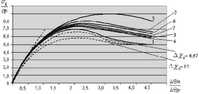
Fig. 1. Dependency graphs σ Sˆ/ σ р from ΔΘ п /ΔΘ р : 1 – p = 0; 2 – p = 1, a = 0; 3 – p = 1, a = 0.25;
4 – p = 1, a = 0.5; 5 – p = 2, a = 0; 6 – p = 2, a = 0.25; 7 – p = 2, a = 0.5
σ ˆ
Also, on Fig. 1 dotted line is constructed relationship dependence S on the argument σ p

flector.
at the p = 0 for the two values Δ xn = 6.67; 12 that determine the size of the Δ Rn M -point re-
From Fig. 1 shows that the expansion of the multipoint reflector in range relative to the location of the focus of the receiving linear AR leads to a decrease in MSD σδ ˆ angular score δ . With the coordinates of the direction finding radio source coinciding, the coordinates of the center of a homogeneous set of statistically independent signal reflectors and the focus of the receiving linear antenna, for a wide class of amplitude distributions in the opening of the receiving antenna, a value of the angular score δ ˆ depends linearly on the value ΔΘ n of the angular size of the multi-point reflector for the values

≤ 1.
Conclusion
-
1. Expressions are obtained for the calculation of the MSD and the displacement of the angular coordinate of a point radio source in the Fresnel zone of a linear AR of a monopulse direction finder when combined with the internal noise of the receiver and angular noise caused by signals of statistically independent point reflectors. It is shown that the obtained expressions are a generalization to the Fresnel zone of the known result of calculating the error during the operation of a monopulse direction finder in the far zone of the receiving antenna.
-
2. It is shown that the error of a monopulse direction finder in the general case is determined jointly by the levels of the side lobes of both the difference and the total directivity characteristics of the receiving antenna in the Fresnel zone.
-
3. It is shown that the expansion of a multipoint reflector in range relative to the location of the focus of the receiving linear AR leads to a decrease in the MSD σδ ˆ of the angular estimate δ ˆ . When the coordinates of the direction finding radio source coincide, the coordinates of the center of a homogeneous set of statistically independent signal reflectors and the focus of the receiving linear antenna for a wide class of amplitude distributions in the aperture of the receiving antenna, the MSD of the angular estimate δ ˆ linearly dependent on the magnitude ΔΘ n of the angular size of the multipoint reflector.
References Errors in measuring the angular coordinate of extended targets by the monopulse method in the Fresnel zone of the linear antenna array
- Ostrovityanov R.V., Basalov F.A. Statisticheskaya teoriya radiolokatsii protyazhennykh tseley [Statistical Theory of Radar Extended Targets]. Moscow, Radio and Communication Publ., 1982, 232 p.
- Monakov A.A., Ostrovityanov G.I. [Accounting for Nonlinearity in the Problems of Statistical Analysis of Signals in a Monopulse Direction Finder]. Radioelectronics, 1986, no. 7, pp. 20-25. (in Russ.)
- Solomonik N.E., Nalivaiko D.A., Zubkov V.A. [Estimation of Errors of Aircraft Direction Finders Caused by Reflected Signals]. Problems of Radio Electronics. Ser. General Questions of Radio Electronics, 1990, iss. 21, pp. 53-59. (in Russ.)
- Gubonin N.S. [Fluctuations of the Phase Front of a Wave Reflected from a Complex Target]. Radio Engineering and Electronics, 1965, vol. X, no. 5, pp. 844-851. (in Russ).
- Ostrovityanov R.V. [To the Question of Angular Noise]. Radio Engineering and Electronics, 1996, no. 4, pp. 592-601. (in Russ).
- Ostrovityanov R.V., Monakov A.A., Khramchenko G.N. [Statistical Characteristics of the Components of a Complex Monopulse Ratio]. Radio Engineering and Electronics, 1988, no. 5, pp. 10881091. (in Russ).
- Monakov A.A. [Estimation of the Angular Coordinate of a Complex Object]. Radio Engineering, 1994, no. 1, pp. 43-47. (in Russ).
- Ostrovityanov R.V., Monakov A.A., Khramchenko G.N. [Radar Measurement of the Parameters of a Group Object]. Radio Engineering, 1994, no. 6, pp. 12-19. (in Russ).
- Shlyahin V.M. [Statistical Characteristics of Errors in Measuring Coordinates of Extended Targets]. Radio Engineering and Electronics, 1983, no. 4, pp. 719-722. (in Russ).
- Monakov A.A., Ostrovityanov R.V., Khramchenko G.N. [Assessment of the Position of the Energy Center of an Extended Object from a Dependent Sample]. Radio Engineering, 1998, no. 1, pp. 19-23. (in Russ).
- Kozlov I.M. [Parameters of a Small-Point Statistical Model of a Complex Radar Target]. News of Higher Education Institutions. Radio Electronics, 2003, vol. 29, no. 6, pp. 51-56. (in Russ).
- Kremer I.Ya., Kremer A.I., Petrov V.M. Prostranstvenno-vremennaya obrabotka signalov [Spatial-Temporal Signal Processing]. Moscow, Radio and Communication Publ., 1984, 224 p.
- Leonov A.I., Fomichev K.I. Monoimpul'snaya radiolokatsiya [Monopulse Radar]. Moscow, Radio and Communication Publ.,1984. 312 p.
- Ragozin A.N. [The Complex angular coordinates of the radar reflection center]. News of Higher Education Institutions. Radio Electronics, 1991, no. 11, pp. 67-69. (in Russ.)
- Dzhavadov G.G. [The Complex Coordinates of the Radar Reflection Center]. News of Higher Education Institutions. Radio Electronics, 1990, vol. 30, no. 1, pp. 52-56.
