Experimental study of temperature distribution in a cyclone-vortex furnace

Author: Kulik Aleksandr V., Dorogov Evgenij Iu., Soloveva Tatyana A., Shtym Konstantin A.
Journal: Журнал Сибирского федерального университета. Серия: Техника и технологии @technologies-sfu
Article in issue: 1 т.14, 2021.
Free access
This article describes the experience and results of experimental study of the temperature distribution in the refractory lining of the gas and liquid fuel cyclone-vortex furnace (CVF). Temperatures were measured with type K thermocouples. Most of the thermocouples are located a depth of 25 mm from the surface combustion chamber. With increasing boiler load observed decrease in temperature and increase of plating unevenness of the temperature distribution in the combustion chamber. This is due to the redistribution of heat generated between the combustion chamber and the firebox as the load increases. The results of heat transfer studies in CVF will lead to a reduction in the thickness of the lining, modernization of the CVF structure. In the future, abandon the use of refractory lining in CVF.
Heat flow, temperature, yclone-vortex furnace, combustion chamber
Short address: https://sciup.org/146281790
IDR: 146281790 | UDC: 621.9 | DOI: 10.17516/1999-494X-0294
Экспериментальное исследование распределения температур в циклонно-вихревом предтопке
Описан опыт и результаты экспериментального исследования распределения температуры в огнеупорной футеровке газомазутного циклонно-вихревого предтопка (ЦВП). Температуры измерялись термопарами типа К. Большинство термопар расположены на глубине 25 мм от поверхности камеры сгорания. С увеличением нагрузки котла наблюдается снижение температуры огнеупорной обмуровки и увеличение неравномерности распределения температуры в камере сгорания. Это связано с перераспределением тепловыделений между камерой сгорания и топкой по мере увеличения нагрузки. Результаты исследований теплообмена в ЦВП приведут к уменьшению толщины футеровки, модернизации ЦВП. В будущем позволит отказаться от использования огнеупорной футеровки в ЦВП.
Text of the scientific article Experimental study of temperature distribution in a cyclone-vortex furnace
In the Far East of Russia, more than 60 boilers have been upgraded to cyclone-vortex technology for burning fuel oil or gas. Based on many years' exploitation, this technology has established itself as a highly efficient. Therefore, as part of the gasification energy sector of the Far East, in 2011, cyclone-vortex furnaces (CVF) were modernized for the combustion of natural gas as the main type of fuel and fuel oil as reserved at the boiler of Vladivostok. The most suitable brands of boilers for modernization: steam boilers BKZ-75–39 F, water boilers KVGM 116.3–150 and water boilers EFM-25/35. [1]
The unique design of the CVF allows you to influence the geometry of the torch in the combustion chamber and in the boiler furnace, as well as to minimize aerodynamic resistance.
2. Description of the object of research
In order to clarify the heat balance of boilers equipped with a CVF, studies of heat exchange processes in the combustion chambers CVF are carried out. The object of research is the water boiler KVGM 116.3–150 MTS – direct-flow water boiler with a heat productivity of 116.3 MW and a water heating temperature of up to 150 °C, upgraded to Cyclone-Vortex Combustion of Gas and Fuel Oil. This boiler is equipped with two combined SMA of opposite layout with a power of 65 MW each.
In the repair period of 2018, 15 thermocouples type K was installed in the refractory lining (of one of the CVF). Figure 1 shows the scheme with the location of thermocouples. For measurements – 141 –
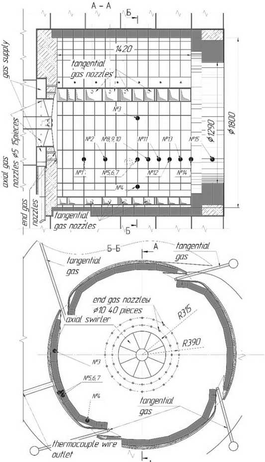
Fig. 1. Scheme of the CVF with the location of thermocouples of volumetric heat emission and heat flux density of thermocouple No. 5–7, 8–10 were mounted on the depth of lining. Thermocouples No 2, 5, 8,11–15 were mounted along the length of the СVF to determine the temperature distribution. Thermocouple No 3, 4, 5. between the air nozzles.
Thermocouples No –5, 8, 11–15 are laid to the depth of 25 mm, No 6 by 40mm, No by 56mm, No by 41mm and No 10–65 mm.
The measurements were carried out at operating conditions in the range of boiler loads from 50 to 100 MW. Air into the combustion chamber of the boiler furnace was supplied from the station's boiler room and from the atmosphere. The air flow rate by CVF was regulated by the guide vanes of the supercharger and regulating gate in front of CVF.
Indications thermocouples were recorded on a laptop through the RS485 interface with the Termodat –22M5 device. To calculate the excess air, the oxygen concentration in the exhaust gases was measured before the smoke exhauster with the AGM-510 gas analyzer.
Operating modes during the measurements are shown in Table 1
Table 1. Modes of operation of the KVGM boiler 116.3–150 MC during measurements.
|
Name |
Mode 1 |
Mode 2 |
Mode 3 |
Mode 4 |
|
Boiler load MW |
58,9 |
67,9 |
81,2 |
90,7 |
|
Gas rate per boiler m3/h |
6772 |
7449 |
8616 |
9858 |
|
Boiler efficiency, η,% |
93,7 |
93,63 |
93,57 |
93,31 |
|
Flue gas temperature, t, оK |
376 |
383 |
389 |
393 |
|
air temperature, t a , оK |
285 |
288 |
285 |
278 |
|
Excess air behind the boiler |
1,35 |
1,28 |
1,25 |
1,2 |
|
The gas pressure at the inputs in CVF, kgf / cm2, |
||||
|
axial input |
0,068 |
0,208 |
0,209 |
0,209 |
|
tangential input |
0,070 |
0,059 |
0,095 |
0,133 |
Results and conclusion
Figure 2 shows a graph of temperature distribution along the length of the combustion chamber at different loads of the boiler. With increasing load, a decrease in the lining temperature and an increase in the uneven distribution of temperatures in the combustion chamber were observed. This phenomenon is
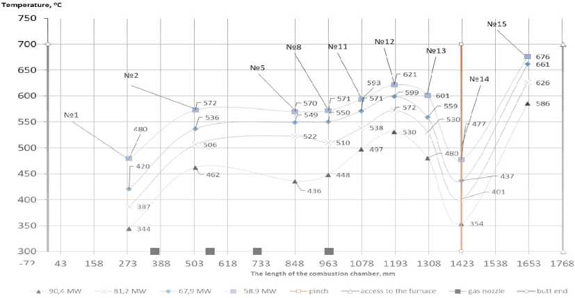
Fig. 2. Laying temperature cyclone-vortex furnace due to the fact that as the load increases, there is a redistribution of heat release between the combustion chamber and the furnace. Such conclusions are also confirmed by previous measurements of the temperature of the gas stream in the combustion chamber. [2] The minimum temperatures were recorded by thermocouples number 1 and number 14. This is due to the presence of wall air flow.
Figure 3 shows the temperature distribution between the air nozzles. As the load increases, the value and temperature profile change. This is due to the fact that there is a difference of 20 mm between the air nozzle and the brickwork. In this place at loads from 65 to 85 MW, formed a stagnation
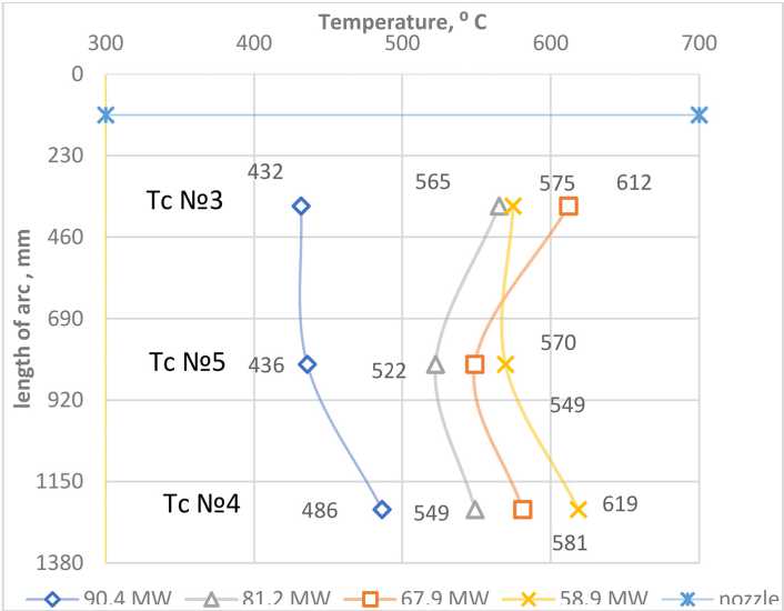
Fig. 3. Laying temperature between nozzles CVF zone, which prevents the lining from cooling.
Figure 4 shows the temperature distribution across the lining depth. Based on these data, it is possible to calculate the specific heat flux through the setting of the combustion chamber in the area of thermocouple No. 5 and No. 8 according to the Fourier law.
The thermal conductivity of fireclay bricks is determined by [3]
From figure 5 it can be seen that as the load increases, the specific heat flux decreases. Characteristic is linear. At a power of 81.2 MW, the maximum of heat release is shifted from zone 8 to 5.
The results of studies of heat transfer in CVF will reduce the thickness of the brickwork, improve the design of the CVF and in the future proceed to the non-walling model of the CVF.
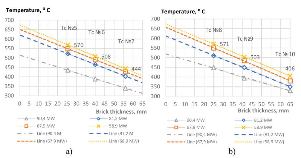
Fig. 4 a) lining temperature at depth № 5. b) lining temperature at depth № 8
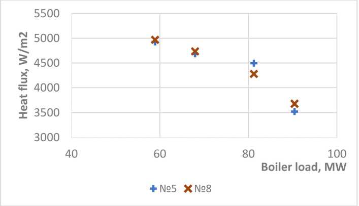
Fig. 5 The dependence of the heat flux density in the zone of laying thermocouples № 5 and № 8
References Experimental study of temperature distribution in a cyclone-vortex furnace
- Shtym A.N., Shtym K. A., Dorogov E. Yu. Boiler installations with cyclone furnaces. 2012
- Lesnykh A.V., Shtym K. A., Solovyova T. A. Methods to reduce the emission of nitrogen oxides nox in cyclone-vortex fuel combustion. In the collection: Proceedings of the International Scientific Conference of Young Scientists and Specialists "Energy Ecology - 2017". 2017. Р. 24-27.
- Industrial ovens. Reference guide for calculations and design: a tutorial. EI Kazantsev. Moscova: Metallurgy, 1964.
