Experimental study on unidirectional flow characteristics of flow diode

Author: Wu Liang, Wang Bao Liang
Journal: Бюллетень науки и практики @bulletennauki
Section: Технические науки
Article in issue: 6 т.9, 2023.
Free access
Flow diode is a kind of control fluid one-way flow of components, it has many advantages, such as simple structure, no rotating parts, no need for external control, power, high reliability, in the medical industry, nuclear industry, petrochemical industry, flow diode has a wide range of applications. By studying relevant literature, combined with the actual situation, based on the experimental study method, using air pump, pressure regulator, 3 d printers and other laboratory equipment, by changing the pump seal the air inlet, simulation of different flow diode under different conditions make the fluid flow through, will pump displacement into displacement, record each air inlet in unit time displacement, and then compared these data, the flow is obtained by carefully analyzing the flow characteristics of diode and the relationship between the fluid flow characteristics diode, it is concluded that: the displacement increases with increase of voltage; when the aperture changes, the flow diode will produce important changes; unstable flow characteristics of variable diameter flow diode.
Flow diode, flow characteristics, experimental study
Short address: https://sciup.org/14127990
IDR: 14127990 | UDC: 621.382.22 | DOI: 10.33619/2414-2948/91/37
Экспериментальное исследование характеристик однонаправленного потока проточных диодов
Проточный диод - это компонент, который управляет односторонним потоком жидкости. Он имеет много преимуществ. Изучая соответствующую литературу и сочетая с реальной ситуацией, проводятся исследования с использованием экспериментального оборудования, такого как воздушные насосы, регуляторы давления и 3D-принтеры, а также путем изменения воздухозаборника крышки воздушного насоса, моделируя различные диоды потока в разных отраслях промышленности. Согласно соотношению, делается вывод, что: смещение увеличивается с увеличением напряжения; при изменении апертуры поток диода потока произведет важные изменения; характеристики потока диода потока переменного диаметра нестабильны.
Text of the scientific article Experimental study on unidirectional flow characteristics of flow diode
Бюллетень науки и практики / Bulletin of Science and Practice
UDC 621.382.22.
Fluid diode is a common one-way flow component in fluid control. Its function is similar to that of traditional check valve. Its main feature is that the resistance is small when it flows in the forward direction, and the resistance is relatively large when it flows in the reverse direction. Compared with check valves, fluid diodes have the advantages of high reliability, no mechanical rotating parts, and less influence from fatigue and corrosion. Therefore, it has been widely used in medicine [1], petrochemical industry [2], nuclear industry [3] and many other fields. For example, the vortex diode check valve with flexible diaphragm cavity used in heart surgery in medicine can effectively prevent blood backflow; the vortex diode pump used to transport radioactive waste water in the nuclear industry can be operated, repaired and replaced remotely, reducing personnel costs. The dose of radiation exposure received. This paper focuses on the flow characteristics of fluid diodes [4].
Compared with other types of fluid diodes, eddy current diodes have a longer history of use and research, simpler structure, higher reliability, and better performance.
In the eddy current diode, the flow field is relatively simple when flowing in the forward direction, while the internal flow field presents a complex three-dimensional strong shear turbulent flow field when flowing in the reverse direction, forming a strong swirl structure near the center of the chamber, similar to[5] In the internal flow state of cyclone separator, eddy current amplifier and other equipment. The typical structure of an eddy current diode consists of three parts: axial tube, chamber and tangential tube, and its performance parameters are determined by two factors: structural parameters and working conditions[6]. Molten salt reactor, as one of the fourth-generation reactor types, has its unique advantages in inherent safety, fuel cycle, miniaturization, effective use of nuclear resources and prevention of nuclear proliferation [7].
Introduction of the experimental equipment
The rated voltage of the small air pump used in this experiment is 115V, and the voltage of household electricity used in our laboratory is 220V. In order to meet the experimental conditions, a voltage regulator is needed to adjust the 220V voltage to 110V and below [7].
This experiment uses a moving coil voltage regulator. The moving coil voltage regulator has a wide range of voltage regulation and a large capacity, but its shortcomings are also obvious, such as low efficiency, large no-load current, and waveforms are prone to occur at low voltages and close to rated voltages. Distortion [8]. Also, the capacity of the moving coil voltage regulator causes resonance in the test circuit. In this experiment, we need to use this voltage regulator to adjust the 220V household electricity to a voltage of 115V and below that meets our experimental requirements.
The micro air pump used in this experiment sucks air from the air and presses the air into a closed space. The air inlet is two round holes with a diameter of about 1mm. The round holes are on a disc with a diameter of about 56 mm. The disc is connected to the cover of the air pump through a screw, and there is a piece between the cover and the disc. The dust-proof sponge is used to prevent the dust in the air from entering the air pump through the air intake hole, which will affect the operation of the compressor and even damage the air pump. There are two small holes on the cover, respectively at the upper left and lower right. There is only one air intake hole on the air pump body, with a diameter of 2 mm. The two symmetrical air intake holes on the cover should prevent the user from disassembling the air pump. Rotate and install the air pump cover to block the air inlet hole of the air pump, thereby affecting the operation of the air pump and even damaging the air pump. There is also a soft rubber pad between the cover and the air pump body to prevent air leakage, and they are connected by four screws. The body of the air pump includes rotors, springs, coils and other parts, which we will not study here. The air outlet of the air pump is a metal pagoda head with a diameter of 2 mm.
The air pump used in this experiment, in order to measure the compressed air volume of the air pump per unit time, we convert the compressed air volume into displacement, that is, put a certain amount of liquid in the filter bottle, water is a kind of liquid, it is difficult to compress, and air and water are in contact , hardly soluble in water. The air pump will suck gas from the air, compress it and discharge it into the filter bottle. The suction filter flask used in this experiment is a glass transparent Erlenmeyer flask with a height of 185 mm and 3 mouths in total, of which the largest mouth is at the top of the bottle with a diameter of 33 mm; the other two mouths are on the body of the bottle. On one left and one right, one up and one down, the diameter of the upper mouth is 3 mm, the distance from the bottom is 116 mm, the diameter of the lower mouth is 3mm, the distance from the bottom is 33 mm, and the diameter of the bottom of the Erlenmeyer flask is 116 mm. In order to control the only experimental variable, we will filter the water in the bottle the amount of control is constant at a height of 70 mm.
The container used to measure water at the beginning of this experiment is a 200 ml beaker. Since some air pumps in the experiment have a relatively large air intake volume, the gas discharged from the air pump will also increase. This part of the gas enters the suction filter bottle and is drained from the lower drain The amount of water discharged will also increase accordingly. The 200 ml beaker we used initially cannot meet the experimental requirements, and the water will quickly overflow the 200 ml beaker. For this reason, this experiment also used a large plastic cup instead of a 200 ml beaker as a water receiving container to receive the water discharged from the suction filter bottle. The maximum mass that the electronic scale used in this experiment can weigh is 200 g, mainly to weigh the quality of the water discharged from the filter bottle, so as to obtain the displacement of the air pump per unit time, and finally compare the displacement with The size and structure of the air pump inlet are compared. In this experiment, rubber hoses are mainly used to transport liquid and gas, that is, the gas compressed by the air pump is transported into the filter bottle, and the liquid discharged from the lower drain of the filter bottle is transported into the beaker. This experiment uses a small printer produced by Chuangxiang 3D Technology Co., Ltd. The printing consumable used is PLA [9]. The inkjet temperature of this material on the 3D printer is 210°C. In order to keep the printed air pump cover with a high air Tightness, we make the printed workpiece wall thickness 3 layers, and 100% filled, try to make the printed workpiece close to the original cover of the air pump when drawing [10].
Experimental steps
The air pump used in this experiment is a micro air pump imported from the United States, the model is AC-110-A1053-D5-0511, its rated voltage is 115V, rated frequency is 50/60Hz, and rated current is 0.28A [11].
Considering the experimental research object, this experiment is to study the unidirectional flow characteristics of the flow diode, so we decided to make a fuss about the air inlet of the air pump. For the flow of Newtonian fluid in the pipe, when the temperature is constant and the internal friction coefficient of the pipe is equal, the diameter of the pipe becomes thicker and the pressure becomes smaller, the flow velocity of the fluid will change from large to small, and the speed will slow down; when When the diameter of the pipe changes from thick to thin, the pressure will increase, the flow velocity of the fluid will change from small to large, and the speed will increase. The air inlet of the air pump is on the cover of the air pump. We only need to consider how to change the size and structure of the air pump air inlet during the experiment. Then measure the relationship between different air inlet sizes and structures and the exhaust volume of the air pump.
-
(1) The air pump cover is required to have a certain strength, which can resist the external impact force of the rotor in the air pump body when it moves, and prevent the air pump rotor from deviating from its originally set track, so that it can run stably; the air pump cover must also have a
certain Air tightness, the gas is compressed in the air pump body, and the cover must not leak air, which will also affect the normal operation of the air pump and affect the experimental results; the air pump cover should also be relatively easy to change the size and structure of the air inlet. In order to meet the above requirements, we decided to use the 3D software Creo to draw the air pump cover, and draw the air pump inlet we need when drawing, and then use the 3D printer to print out the cover we need for this experiment [12].
We fix the printed air pump cover on the air pump with screws, measure the exhaust volume of the air pump per unit time by direct or indirect methods, and find out the difference between different air inlet sizes and structures and the exhaust volume of the air pump by analyzing the data. relation.
-
(2) In order to measure the exhaust volume, we connect the exhaust port of the air pump to the upper air inlet of the filter bottle, and the lower end is used as the drain port. Add a certain amount of liquid into the filter bottle, and the gas compressed by the air pump enters the inside of the filter bottle through the exhaust port of the air pump and through the upper air inlet of the filter bottle. Since the upper bottle mouth of the filter bottle is blocked and sealed by a rubber stopper, The lower drain is open, and the part of the gas discharged by the air pump will increase the pressure in the filter bottle, so that the liquid in the filter bottle is pressed and discharged from the filter bottle through the lower drain, and the quality of this part of the drainage can be obtained. Air pump displacement.
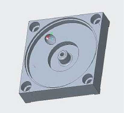
Figure 1. Air pump capping drawing by Creo
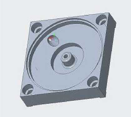
First we need to prepare the cover according to the size of the air pump cover. According to our proposed test method, we plan to use a 3D printer to print out the air pump cover that changes the size of the air inlet. The air pump is a kind of equipment that needs to be very airtight. In order to make the cover we print fit perfectly and install it on the air pump without leaking, we need to be very strict when measuring the size of the original air pump cover. When measuring, we use vernier calipers with high precision to record the size of every detail. When drawing, we used Creo this time. After drawing the original cover, we continued to open the hole. Because opening a straight hole will open the hole to the outside of the cover, so we decided to open an oblique hole, that is, keep the The position and size of the lower air inlet place the position of the upper air inlet on the upper end of the cover, so we need to reconstruct the plane on the drawing, draw a right-angled trapezoid on this surface, and the right-angled side of the right-angled trapezoid passes through the cover The center of the lower inlet of the air intake, and then we rotate the trapezoid with the right- angled side as the central axis to obtain the air intake hole of the cover. Figure 1 is a screenshot of the 3D drawing during the experiment, and then we will import the drawn 3D drawing into the 3D printer for printing [13].
Due to the format problem, we converted the format of the original drawing, and converted the original format with the suffix "prt" into the format with the suffix "stl". After completing the format conversion, we use Creative 3D slicing software to make slices. When printing, we require the workpiece to be highly airtight, so we require three layers of wall thickness to be printed, and the filling density in the middle is 100%, so each It takes a long time to print the workpiece. According to computer calculation, it takes about five and a half hours to seal each air pump. We save the organized slices to the SD card of the printer and start printing. Figure 2 is the finished slice model [14].
After printing, we remove it from the printer workbench and break off the base. When printing, in order to keep the workpiece from deforming, the printer automatically supports the place where the sponge was originally placed. We also need to use tools to buckle the support. Lose. Such an air pump cover is prepared, installed on the air pump, and tested to operate normally. Since the rated voltage of the micro air pump we use is 115V, the electricity used in the laboratory is our usual 220V voltage. In order to make our micro air pump work normally, we found a voltage regulator in the laboratory, which needs to adjust the 220V voltage to 115V and below voltage. Connect the air pump to the regulator with a wire, and find a plug to connect the regulator to the power supply. Then connect the exhaust port of the air pump with the air inlet of the filter bottle. The two ports are pagoda heads, and they can be connected directly with a hose. However, due to the size of the air pump exhaust port and the air inlet of the filter bottle The size difference is too big, so we use two sections of hose to connect the exhaust port of the air pump and the intake port of the filter bottle, and then connect the two sections of hose with a pagoda head, so that the exhaust port of the air pump and the suction port of the suction bottle can be connected. The filter bottle inlet is connecte .
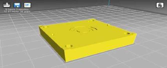
Figure 2. 3d slicing model
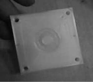
Figure 3. The air pump cover is done
Since we want to weigh or measure the volume of the liquid discharged from the filter flask, we take out one end of the hose and connect it to the drain of the filter flask, and put the other end of the hose into the beaker. In order to prevent the siphon phenomenon, we deliberately raised this section of hose near the beaker side so that its height was greater than the liquid height in the suction flask. According to the debugging of the experimental equipment, we are going to measure the displacement of the air pump under the voltage of 80V. First, we turn the knob of the voltage regulator to the position indicated by 80V, take a piece of dry ice and put it on the fin of the air pump, wait for two minutes for the dry ice to evaporate, and turn on the power after the air pump cools down, this is to prevent the air pump from running for too long, thereby affecting the exhaust efficiency and the experimental effect, and it is also to control the experimental variable to be one. Also keep dry ice on the air pump fins throughout the experiment. Add water at a height of 70 mm to the filter bottle, and keep the height of the water in the filter bottle at about 70 mm before each experiment, keep the quality of water and gas in the filter bottle unchanged, and control its variables to be unique. The beaker used to drain the water from the filter flask was taken to the balance and weighed in advance, and recorded. Prepare a stopwatch with an accuracy of about two decimal places, and try to make the experimental results as accurate as possible. While pressing the power switch, press the stopwatch to start timing. Try to make the air pump run for a certain period of time under stable operating conditions. When the range of the balance is met, turn off the power switch. At the same time, the stopwatch also stops timing and records. Air pump runs time. Take the beaker to the balance and weigh it, record the obtained data on the Excel table, and calculate the displacement of the air pump per unit time. In order to exclude the influence of other factors during the experiment, this experiment conducted 10 sets of experiments on the operation of each air pump cover under each working condition. For example, 10 sets of experiments were carried out on the No10 groups of experiments are being carried out under the working condition of 95V. Then unscrew the screw on the air pump cover, replace with another cover and repeat the above steps. In this experiment, 6 air pump covers were prepared, and the experiment was repeated 120 times. The original cover of the air pump was tested 10 times under the two working conditions. After the experiment, the data were compared and analyzed.
Experimental data and data analysis
This experiment is to study the flow characteristics of the flow diode. According to the experimental design, due to time constraints, we used a 3D printer to print six air pump covers, and each of the air pump covers is the same except for the size of the air inlet. For the convenience of representation, we divide the air pump cover air inlet into "M" end and "N" end, where the "M" end is the size of the upper air intake, and the "N" end is the size of the lower air intake. And the size of the "M" end and "N" end of each cover air inlet is measured through the drawings, see Table 1.
Table 1
COVER SIZE
|
Cover number |
Upper air inlet size ( in2) |
Lower air inlet size ( in2 ) |
|
4 |
58.1 |
2.81 |
|
6 |
33.2 |
1.49 |
|
8 |
2.61 |
2.61 |
|
9 |
21.3 |
1.68 |
|
10 |
46.6 |
1.32 |
|
11 |
68.36 |
1.43 |
In order to make the experimental data more convincing and make the experiment more comprehensive, we arrange two working conditions, one is to make the air pump work at 80V, and the other is to make the air pump work at 95V. And record ten sets of data for each working condition, that is, record 20 sets of data for each cover, plus the cover of the air pump itself for comparison, a total of 140 sets of data, see Table 2 for specific data. During the experiment, we tried to control other variables, such as temperature and so on. I sort out the data in Table 1 and Table 2, and put the sorted data in Table 3. According to Table 3, we can see that the displacement of the same air pump cover is very different under different working conditions: the average flow rate of the original cover of the air pump is only 0.197g/s under the working condition of 80V, but in the Under the working condition of 95V, the flow rate reaches 16.6443g/s, and the displacement of the original air pump cover under the working condition of 95V is more than 84 times that under the working condition of 80V.
Table 2
FLOW RATE OF EACH SEAL OF AIR PUMP IN EACH WORKING CONDITION
|
Cover number |
Voltage/(v) |
Liquid high/cm |
Work time/s |
Drain weight g |
Flow/g/s |
Average traffic/g/s |
|
Genuine |
80 |
7 |
209.30 |
45.83 |
0.2190 |
0.1970 |
|
Genuine |
80 |
7 |
209.69 |
50.60 |
0.2413 |
|
|
Genuine |
80 |
7 |
209.94 |
50.85 |
0.2422 |
|
|
Genuine |
80 |
7 |
209.50 |
41.64 |
0.1988 |
|
|
Genuine |
80 |
7 |
209.88 |
35.04 |
0.1670 |
|
|
Genuine |
80 |
7 |
209.61 |
36.38 |
0.1736 |
|
|
Genuine |
80 |
7 |
209.69 |
29.79 |
0.1421 |
|
|
Genuine |
80 |
7 |
210.17 |
43.14 |
0.2053 |
|
|
Genuine |
80 |
7 |
209.73 |
39.40 |
0.1879 |
|
|
Genuine |
80 |
7 |
209.47 |
40.38 |
0.1928 |
|
|
Genuine |
95 |
7 |
5.73 |
89.50 |
15.6195 |
16.6443 |
|
Genuine |
95 |
7 |
5.90 |
91.66 |
15.5356 |
|
|
Genuine |
95 |
7 |
5.58 |
87.68 |
15.7133 |
|
|
Genuine |
95 |
7 |
5.83 |
95.05 |
16.3036 |
|
|
Genuine |
95 |
7 |
5.74 |
95.07 |
16.5627 |
|
|
Genuine |
95 |
7 |
5.69 |
97.36 |
17.1107 |
|
|
Genuine |
95 |
7 |
5.66 |
96.65 |
17.0760 |
|
|
Genuine |
95 |
7 |
5.57 |
97.47 |
17.4991 |
|
|
Genuine |
95 |
7 |
5.52 |
95.65 |
17.3279 |
|
|
Genuine |
95 |
7 |
5.50 |
97.32 |
17.6945 |
|
|
4 |
80 |
7 |
62.54 |
83.38 |
1.3332 |
1.3310 |
|
4 |
80 |
7 |
63.45 |
82.87 |
1.3061 |
|
|
4 |
80 |
7 |
63.02 |
84.22 |
1.3364 |
|
|
4 |
80 |
7 |
63.80 |
86.02 |
1.3483 |
|
|
4 |
80 |
7 |
62.32 |
82.64 |
1.3261 |
|
|
4 |
80 |
7 |
62.51 |
84.91 |
1.3583 |
|
|
4 |
80 |
7 |
62.76 |
83.97 |
1.3380 |
|
|
4 |
80 |
7 |
62.06 |
81.17 |
1.3079 |
|
|
4 |
80 |
7 |
62.07 |
82.32 |
1.3262 |
|
|
4 |
80 |
7 |
61.93 |
82.31 |
1.3291 |
|
|
4 |
95 |
7 |
12.15 |
85.90 |
7.0700 |
7.0938 |
|
4 |
95 |
7 |
12.38 |
88.47 |
7.1462 |
|
|
4 |
95 |
7 |
12.23 |
87.16 |
7.1267 |
|
|
4 |
95 |
7 |
12.54 |
89.89 |
7.1683 |
|
|
4 |
95 |
7 |
12.77 |
90.92 |
7.1198 |
|
|
4 |
95 |
7 |
12.05 |
84.89 |
7.0448 |
|
|
4 |
95 |
7 |
12.09 |
85.77 |
7.0943 |
|
|
4 |
95 |
7 |
12.58 |
88.93 |
7.0692 |
|
|
4 |
95 |
7 |
12.37 |
87.19 |
7.0485 |
|
|
4 |
95 |
7 |
12.03 |
84.82 |
7.0507 |
|
|
6 |
80 |
7 |
95.21 |
87.29 |
0.9168 |
0.8455 |
|
6 |
80 |
7 |
95.38 |
82.57 |
0.8657 |
|
Cover number |
Voltage/(v) |
Liquid high/cm |
Work time/s |
Drain weight g |
Flow/g/s |
Average traffic/g/s |
|
6 |
80 |
7 |
95.19 |
83.74 |
0.8797 |
|
|
6 |
80 |
7 |
95.57 |
81.04 |
0.8480 |
|
|
6 |
80 |
7 |
95.60 |
79.87 |
0.8355 |
|
|
6 |
80 |
7 |
100.93 |
81.67 |
0.8092 |
|
|
6 |
80 |
7 |
95.63 |
78.55 |
0.8214 |
|
|
6 |
80 |
7 |
95.21 |
79.17 |
0.8315 |
|
|
6 |
80 |
7 |
95.83 |
79.86 |
0.8334 |
|
|
6 |
80 |
7 |
95.62 |
77.84 |
0.8141 |
|
|
6 |
95 |
7 |
74.88 |
90.14 |
1.2038 |
1.2207 |
|
6 |
95 |
7 |
74.79 |
91.07 |
1.2177 |
|
|
6 |
95 |
7 |
74.03 |
90.49 |
1.2223 |
|
|
6 |
95 |
7 |
74.44 |
90.64 |
1.2176 |
|
|
6 |
95 |
7 |
74.34 |
90.42 |
1.2163 |
|
|
6 |
95 |
7 |
74.53 |
90.18 |
1.2100 |
|
|
6 |
95 |
7 |
74.24 |
90.79 |
1.2229 |
|
|
6 |
95 |
7 |
74.90 |
91.11 |
1.2164 |
|
|
6 |
95 |
7 |
75.79 |
94.34 |
1.2448 |
|
|
6 |
95 |
7 |
74.74 |
92.29 |
1.2348 |
|
|
9 |
80 |
7 |
23.12 |
83.03 |
3.5913 |
3.1814 |
|
9 |
80 |
7 |
24.06 |
80.44 |
3.3433 |
|
|
9 |
80 |
7 |
27.43 |
87.67 |
3.1961 |
|
|
9 |
80 |
7 |
23.93 |
75.51 |
3.1555 |
|
|
9 |
80 |
7 |
23.88 |
77.30 |
3.2370 |
|
|
9 |
80 |
7 |
23.85 |
73.57 |
3.0847 |
|
|
9 |
80 |
7 |
23.11 |
70.71 |
3.0597 |
|
|
9 |
80 |
7 |
23.67 |
71.14 |
3.0055 |
|
|
9 |
80 |
7 |
23.86 |
73.68 |
3.0880 |
|
|
9 |
80 |
7 |
23.83 |
72.75 |
3.0529 |
|
|
9 |
95 |
7 |
23.35 |
85.35 |
3.6552 |
3.8798 |
|
9 |
95 |
7 |
23.35 |
89.05 |
3.8137 |
|
|
9 |
95 |
7 |
23.74 |
91.49 |
3.8538 |
|
|
9 |
95 |
7 |
22.24 |
85.39 |
3.8395 |
|
|
9 |
95 |
7 |
22.52 |
88.41 |
3.9258 |
|
|
9 |
95 |
7 |
22.70 |
88.46 |
3.8969 |
|
|
9 |
95 |
7 |
22.58 |
88.06 |
3.8999 |
|
|
9 |
95 |
7 |
22.10 |
84.78 |
3.8362 |
|
|
9 |
95 |
7 |
21.56 |
86.72 |
4.0223 |
|
|
9 |
95 |
7 |
23.15 |
93.86 |
4.0544 |
|
|
10 |
80 |
7 |
90.66 |
81.71 |
0.9013 |
0.8905 |
|
10 |
80 |
7 |
90.61 |
81.37 |
0.8980 |
|
|
10 |
80 |
7 |
90.63 |
77.03 |
0.8499 |
|
|
10 |
80 |
7 |
90.58 |
77.88 |
0.8598 |
|
|
10 |
80 |
7 |
90.62 |
81.84 |
0.9031 |
|
|
10 |
80 |
7 |
90.54 |
84.04 |
0.9282 |
|
|
10 |
80 |
7 |
90.57 |
82.03 |
0.9057 |
|
|
10 |
80 |
7 |
90.72 |
79.83 |
0.8800 |
|
|
10 |
80 |
7 |
90.77 |
80.61 |
0.8881 |
|
|
10 |
80 |
7 |
90.64 |
80.72 |
0.8906 |
|
|
10 |
95 |
7 |
13.47 |
85.39 |
6.3393 |
6.2803 |
|
Cover number |
Voltage/(v) |
Liquid high/cm |
Work time/s |
Drain weight g |
Flow/g/s |
Average traffic/g/s |
||
|
10 |
95 |
7 |
15.16 |
92.13 |
6.0772 |
|||
|
10 |
95 |
7 |
13.06 |
81.63 |
6.2504 |
|||
|
10 |
95 |
7 |
12.55 |
80.49 |
6.4135 |
|||
|
10 |
95 |
7 |
14.49 |
88.50 |
6.1077 |
|||
|
10 |
95 |
7 |
13.83 |
89.95 |
6.5040 |
|||
|
10 |
95 |
7 |
13.73 |
83.09 |
6.0517 |
|||
|
10 |
95 |
7 |
13.67 |
84.41 |
6.1748 |
|||
|
10 |
95 |
7 |
13.61 |
85.86 |
6.3086 |
|||
|
10 |
95 |
7 |
13.66 |
89.82 |
6.5754 |
|||
|
11 |
80 |
7 |
20.60 |
91.28 |
4.4311 |
4.1397 |
||
|
11 |
80 |
7 |
20.16 |
83.41 |
4.1374 |
|||
|
11 |
80 |
7 |
20.71 |
84.27 |
4.0690 |
|||
|
11 |
80 |
7 |
21.93 |
90.80 |
4.1404 |
|||
|
11 |
80 |
7 |
20.60 |
84.50 |
4.1019 |
|||
|
11 |
80 |
7 |
21.54 |
88.24 |
4.0966 |
|||
|
11 |
80 |
7 |
20.66 |
83.66 |
4.0494 |
|||
|
11 |
80 |
7 |
20.58 |
84.02 |
4.0826 |
|||
|
11 |
80 |
7 |
20.85 |
86.03 |
4.1261 |
|||
|
11 |
80 |
7 |
20.59 |
85.70 |
4.1622 |
|||
|
11 |
95 |
7 |
13.87 |
79.62 |
5.7404 |
5.5510 |
||
|
11 |
95 |
7 |
13.67 |
80.74 |
5.9064 |
|||
|
11 |
95 |
7 |
13.74 |
81.64 |
5.9418 |
|||
|
11 |
95 |
7 |
13.45 |
74.95 |
5.5725 |
|||
|
11 |
95 |
7 |
13.56 |
77.68 |
5.7286 |
|||
|
11 |
95 |
7 |
16.47 |
89.35 |
5.4250 |
|||
|
11 |
95 |
7 |
14.04 |
76.91 |
5.4779 |
|||
|
11 |
95 |
7 |
15.69 |
84.25 |
5.3697 |
|||
|
11 |
95 |
7 |
14.01 |
73.51 |
5.2470 |
|||
|
11 |
95 |
7 |
14.13 |
72.07 |
5.1005 |
|||
|
8 |
80 |
7 |
57.55 |
110.84 |
1.9260 |
1.9535 |
||
|
8 |
80 |
7 |
55.69 |
110.22 |
1.9792 |
|||
|
8 |
80 |
7 |
55.85 |
115.04 |
2.0598 |
|||
|
8 |
80 |
7 |
55.61 |
108.95 |
1.9592 |
|||
|
8 |
80 |
7 |
55.61 |
110.64 |
1.9896 |
|||
|
8 |
80 |
7 |
55.75 |
108.99 |
1.9550 |
|||
|
8 |
80 |
7 |
55.38 |
106.91 |
1.9305 |
|||
|
8 |
80 |
7 |
55.71 |
108.07 |
1.9399 |
|||
|
8 |
80 |
7 |
55.78 |
106.70 |
1.9129 |
|||
|
8 |
80 |
7 |
55.58 |
104.67 |
1.8832 |
|||
|
8 |
95 |
7 |
13.25 |
141.16 |
10.6536 |
10.3537 |
||
|
8 |
95 |
7 |
12.25 |
125.86 |
10.2743 |
|||
|
8 |
95 |
7 |
12.79 |
129.79 |
10.1478 |
|||
|
8 |
95 |
7 |
12.61 |
131.47 |
10.4259 |
|||
|
8 |
95 |
7 |
12.70 |
132.37 |
10.4228 |
|||
|
8 |
95 |
7 |
12.73 |
132.59 |
10.4156 |
|||
|
8 |
95 |
7 |
13.38 |
140.24 |
10.4813 |
|||
|
8 |
95 |
7 |
12.98 |
132.78 |
10.2296 |
|||
|
8 |
95 |
7 |
14.17 |
142.77 |
10.0755 |
|||
|
8 |
95 |
7 |
13.94 |
145.13 |
10.4110 |
|||
|
Тип лицензии CC: Attribution 4.0 International (CC BY 4.0) |
294 |
|||||||
It turns out that the air inlet of the air pump cover is made with a hole at the bottom of the circular groove, which is similar to a very regular small cylinder. Two faces, so it is not convenient for us to measure its area. However, we can calculate the size of the upper air inlet and the lower air inlet of the air pump cover that we draw with 3D software on the drawings.
Table 3
DATA CONSOLIDATION
|
Cover number |
Voltage/(v) |
Average traffic ( g/s ) |
Size / (in2 ) |
||
|
Upper air inlet size |
(in2 ) |
Lower air inlet size (in2) |
|||
|
Genuine |
80.0000 |
0.1970 |
|||
|
95.0000 |
16.6443 |
||||
|
4 |
80.0000 |
1.3310 |
2.81 |
58.1 |
|
|
95.0000 |
7.0938 |
||||
|
6 |
80.0000 |
0.8455 |
1.49 |
33.2 |
|
|
95.0000 |
1.2207 |
||||
|
9 |
80.0000 |
3.1814 |
1.68 |
21.3 |
|
|
95.0000 |
3.8798 |
||||
|
10 |
80.0000 |
0.8905 |
1.32 |
46.6 |
|
|
95.0000 |
6.2803 |
||||
|
11 |
80.0000 |
4.1397 |
1.43 |
68.3 |
|
|
95.0000 |
5.5510 |
||||
|
8 |
80.0000 |
1.9535 |
2.61 |
2.6 |
|
|
95.0000 |
10.3537 |
||||
Let's look at the air pump cover numbered "4". Due to a software problem, the units of the air intake area we got from the graph are imperial units. The size of the upper air inlet of the air pump cover numbered "4" is 58.1 in2, and the size of the lower air inlet is 2.81 in2. The average flow rate of the cover numbered "4" is 1.331 in2 at 80V, the average flow rate is 7.0938 in2 under the 95V working condition, the ratio of the size of the upper inlet port to the size of the lower inlet port is about 20.66:1, and the ratio of the average flow rate under the two working conditions is about 5.33:1. Under the working condition of 80V, the ratio of the displacement of the cover to the original cover is 6.76:1; under the condition of 95V, the ratio of the displacement of the cover to the original cover is 0.43:1.
The size of the air pump cover with number "6" is 33.2 in2, and the size of the lower inlet is 1.49 in^2. The cover with number "6" has an average flow rate of 0.8455 at 80V in^2, the average flow rate is 1.2207in^2 under the 95V working condition, the ratio of the size of the upper inlet port to the size of the lower inlet port is about 22.26:1, and the ratio of the average flow rate under the two working conditions is about 1.44:1. Under the working condition of 80V, the ratio of the displacement of the cover to the original cover is 4.29:1; under the condition of 95V, the ratio of the displacement of the cover to the original cover is 0.07:1. Under the working condition of 80V, the ratio of the exhaust volume of this cover to the cover numbered "4" is 0.64:1; under the working condition of 95V, the ratio of the exhaust volume of the cover the ratio is 0.17:1.
The size of the air pump cover with number "9" is 21.3 in2, and the size of the lower inlet is 1.68in2. The cover with number "9" has an average flow rate of 3.1814 in2 at 80V, the average flow rate is 3.8798 in2 under the 95V working condition, the ratio of the size of the upper inlet port to the size of the lower inlet port is about 12.67:1, and the ratio of the average flow rate under the two working conditions is about 1.22:1. Under the working condition of 80V, the ratio of the displacement of the cover to the original cover is 16.15:1; under the condition of 95V, the ratio of the displacement of the cover to the original cover is 0.23:1. Under the working condition of 80V, the ratio of the exhaust volume of this cover to the cover numbered "4" is 2.39:1; under the working condition of 95V, the ratio of the exhaust volume of the cover the ratio is 0.55:1. Under the working condition of 80V, the ratio of the exhaust volume of the cover and the cover numbered "6" is 3.76:1; under the working condition of 95V, the ratio of the exhaust volume of the cover and the The ratio is 3.18:1.
The size of the upper air inlet of the air pump cover numbered "10" is 46.6 in2, and the size of the lower air inlet is 1.32 in2. The average flow rate of the cover numbered "10" is 0.8905 at 80V in2, the average flow rate is 6.2803 in2 under the 95V working condition, the ratio of the size of the upper inlet port to the size of the lower inlet port is about 35.40:1, and the ratio of the average flow rate under the two working conditions is about 7.05:1. Under the working condition of 80V, the ratio of the displacement of the cover to the original cover is 4.52:1; under the condition of 95V, the ratio of the displacement of the cover to the original cover is 0.38:1. Under the working condition of 80V, the ratio of the exhaust volume of the cover and the cover numbered "4" is 0.67:1; under the working condition of 95V, the ratio of the exhaust volume of the cover the ratio is 0.89:1. Under the working condition of 80V, the ratio of the exhaust volume of the cover to the cover numbered "6" is 1.05:1; under the working condition of 95V, the ratio of the exhaust volume of the cover the ratio is 5.14:1. Under the working condition of 80V, the ratio of the exhaust volume of this cover to the cover numbered "9" is 0.28:1; under the working condition of 95V, the ratio of the exhaust volume of the cover the ratio is 1.62:1.
The size of the upper air inlet of the air pump cover numbered "11" is 68.3 in2, and the size of the lower air inlet is 1.43 in2. The average flow rate of the cover numbered "11" is 4.1397 at 80V in2, the average flow rate is 5.5510 in2 under the 95V working condition, the ratio of the size of the upper inlet port to the size of the lower inlet port is about 47.77:1, and the ratio of the average flow rate under the two working conditions is about 1.34:1. Under the working condition of 80V, the ratio of the displacement of the cover to the original cover is 21.02:1; under the condition of 95V, the ratio of the displacement of the cover to the original cover is 0.33:1. Under the working condition of 80V, the ratio of the exhaust volume of the cover and the cover numbered "4" is 3.11:1; under the working condition of 95V, the ratio of the exhaust volume of the cover The ratio is 0.78:1. Under the working condition of 80V, the ratio of the exhaust volume of this cover to the cover numbered "6" is 4.90:1; under the working condition of 95V, the ratio of the exhaust volume of the cover the ratio is 4.55:1. Under the working condition of 80V, the ratio of the exhaust volume of this cover to the cover numbered "9" is 1.30:1; under the working condition of 95V, the ratio of the exhaust volume of the cover the ratio is 1.43:1. Under the working condition of 80V, the ratio of the exhaust volume of the cover and the cover numbered "10" is 4.65:1; the ratio is 0.88:1.
The size of the upper air inlet of the air pump cover numbered "8" is 2.61 in2, the size of the lower air inlet is 2.61 in2, and the upper and lower openings have the same area. Same size holes. The cover numbered "8" has an average flow rate of 1.9535 in2 under the 80V working condition, and an average flow rate of 10.3537 in2 under the 95V working condition, and the ratio of the size of the upper air inlet to the lower air inlet is 1:1, the ratio of the average flow rate under the two working conditions is about 5.30:1. Under the working condition of 80V, the ratio of the displacement of the cover to the original cover is 9.92:1; under the condition of 95V, the ratio of the displacement of the cover to the original cover is 0.62:1. Under the working condition of 80V, the ratio of the exhaust volume of the cover and the cover numbered "4" is 1.47:1; under the working condition of 95V, the ratio of the exhaust volume of the cover the ratio is 1.46:1. Under the working condition of 80V, the ratio of the exhaust volume of the cover to the cover numbered "6" is 2.31:1;
under the working condition of 95V, the ratio of the exhaust volume of the cover the ratio is 8.48:1. Under the working condition of 80V, the ratio of the exhaust volume of the cover and the cover numbered "9" is 0.61:1; the ratio is 2.67:1. Under the working condition of 80V, the ratio of the exhaust volume of the cover and the cover numbered "10" is 2.19:1; the ratio is 1.65:1. Under the working condition of 80V, the ratio of the exhaust volume of this cover to the cover numbered "11" is 0.47:1; under the working condition of 95V, the ratio of the exhaust volume of the cover the ratio is 1.87:1.
It can be seen from the data analysis that when two different air pump covers are involved in the operation under the same working condition, the exhaust volume does not change linearly, and the ratio of the exhaust volume obtained by the same air pump cover under the two working conditions is also relatively large. Difference the displacement of the air pump is not only related to the size and structure of the air pump cover, but also related to the working conditions of the air pump. We can see that the flow characteristics of the flow diode are closely related to the structure and size of the diode, and are also closely related to the working conditions. We need further and more detailed experiments to obtain further results.
It can be seen from the figure that there is a great relationship between the displacement of the air pump and the ratio of the upper air inlet to the lower air inlet. During the experiment, the size change of the air pump cover is not detailed enough, so the data statistics are not enough. Linear, with great fluctuations, I believe that through detailed experiments, a complete set of methods for optimizing the flow characteristics of flow diodes will be formed.
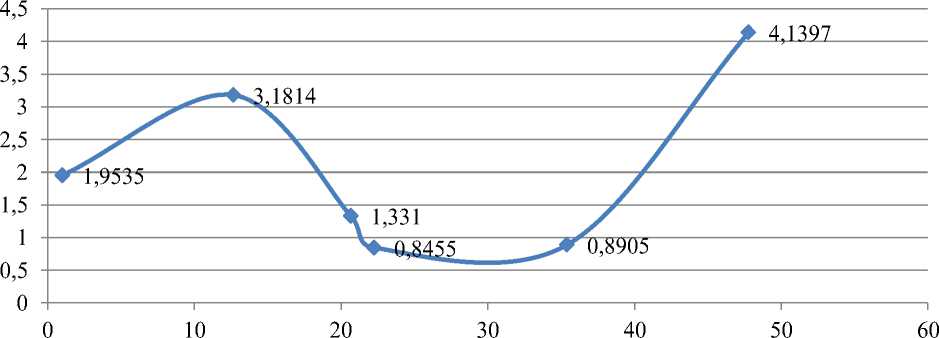
Figure 4. Flow variation of the relation between cap size ratio and average flow rate
The detailed experimental process is as follows: first, fix the size of the upper air inlet or the lower air inlet. Let us take the size of the lower air inlet as an example, and change the ratio of the air pump upper air inlet to the air pump lower air inlet from 1 Gradually increase evenly to measure the change of the air pump displacement; then gradually increase the size of the lower inlet of the air intake, and each time the size change is increased, we will measure the corresponding air pump displacement, so that many groups can be measured Experimental data, it is better to integrate them into a drawing to facilitate the optimization of the flow of the flow diode [15].
References Experimental study on unidirectional flow characteristics of flow diode
- Singh, P. I. (1981). U.S. Patent No. 4,259,988. Washington, DC: U.S. Patent and Trademark Office.
- Michael, J., & Bowe, A. L. W. (1989). Fluidic apparatus.US Patent 4887628. Dec. 19.
- Guo, Yanhua (2004). Experimental research on the performance of nuclear pneumatic pulsed liquid jet pump and eddy current diode pump. Tsinghua University.
- Tesla, N. (1920). Valvular conduit.US Patent 1329559, Feb. 3.
- John, F. & Meadowbrook, P. (1978). Fluidic seal.US Patent 4092908, Jun.6.
- Jr. G. L Y., Elkassabgi, Y. M., & Leon, G. I. (2011). D..Vortex Diode Analysis and Testing for Fluoride Salt-Cooled High-Temperature Reactors. ORNLTM-2011/425. Oak Ridge National Laboratory.
- Jan, E. (1980). Nieuwerkerkaande I. Fluid diode. US Patent 4187874, Feb. 12.
- Zobel, R. (1930). Experiments on a Hydraulic Reversing Throat. Mitt. Hydraul. Inst. Munich., 8(19), 1-47.
- Kulkarni, A. A., Ranade, V. V., Rajeev, R., & Koganti, S. B. (2008). CFD simulation of flow in vortex diodes. AIChE journal, 54(5), 1139-1152. https://doi.org/10.1002/aic.11439
- Wang, Leqin, Sun, Qingjun, & Jiao, Lei. (2008). Simulation of internal flow and highresistance characteristics of large-flow eddy current diodes. Journal of Engineering Thermophysics, 29(12), 2046-2048.
- Jiao, Lei, Chen, Zongnan, & Liu, Shiguo (2011). Numerical simulation of threedimensional strongly swirling tip flow in eddy current diodes. Journal of Engineering Thermophysics, 32(11), 1855-1858.
- Priestman, G. H. (1987). A study of vortex throttles Part 1: Experimental. Proceedings of the Institution of Mechanical Engineers, Part C: Journal of Mechanical Engineering Science, 201(5), 331-336. https://doi.org/10.1243/PIME_PROC_1987_201_131
- Kulkarni, A. A., Ranade, V. V., Rajeev, R., & Koganti, S. B. (2009). Pressure drop across vortex diodes: Experiments and design guidelines. Chemical Engineering Science, 64(6), 1285-1292. https://doi.org/10.1016/j.ces.2008.10.060
- Dai, Y., Guo, Z., & Li, J. (2019, October). Numerical Simulation of Flow Characteristics of Vortex Diode with Multi-tangential Tubes. In IOP Conference Series: Earth and Environmental Science (Vol. 330, No. 5, p. 052008). IOP Publishing.
