Face Detection and Auto Positioning for Robotic Vision System

Author: Muralindran Mariappan, Tan Wei Fang, Manimehala Nadarajan, Norfarariyanti Parimon
Journal: International Journal of Image, Graphics and Signal Processing(IJIGSP) @ijigsp
Article in issue: 12 vol.7, 2015.
Free access
Robotic vision system has taken a great leap in the field of robotics. Vision system is an essential tool to be implemented in a robot for visual communication between robot and human especially in the application of Tele-Diagnostic Robot. The robot vision system must always be in the field of view. The ability for the vision system to automatically track the person in communication is crucial for the remote medical specialist. To circumvent this problem, a face detection technique is implemented and it is performed using skin color segmentation with two color space which are YCbCr and HSV. Besides that, morphological operations are also done to detect the face region accurately. Two DOF servo mechanism were designed to ensure that the servo motor rotates to centralize the detected face region. A real-time testing were conducted and it was found that this system results a good performance.
Face detection, auto positioning, skin colour segmentation, servo motor
Short address: https://sciup.org/15013929
IDR: 15013929
Text of the scientific article Face Detection and Auto Positioning for Robotic Vision System
Published Online November 2015 in MECS
Robotic vision system is a fundamental tool to be applied in many robotics field such as education, medical, agriculture, military and others. Vision system deployed in robots enable robots to see, learn and understand their environment factors using sense of vision. A real working environment of a robot is dynamic and unknown where a real-time conditions is mostly unpredictable. Thus, vision system in robots are designed as it has sophisticated algorithms to execute in achieving challenging task. Vision systems in robots are mainly developed to create a good platform for Human Robot Interaction (HRI) for communication through sensors and actuators. Many research has been carried out in the last decades as vision system has a high potential for extended application such as object tracking and face detection.
Face detection is a biometric method that has been blooming recently. Biometric methods are being deployed to robots to benefit human-robot interactions (HRI). This is due to the reason that biometric methods have several advantages. Biometric method is defined as “something that you are” [1]. Examples of biometric techniques are face, iris, DNA, palmprint, keystroke and etc. These are divided into two categories which are physiological and behavioral. The main advantage of using face for robotic vision is due to its advantage of having a contactless system between the robot and human. Besides that, face region can be captured from a far distance and it is not easy to be altered unless due to severe injuries. There are several robots that uses face technology as a part of vision system. For an example, RP-Vita [2], Security Warrior [3] and MTR [4]. These are some of the telepresence medical robots that uses face detection for audio- visual communication.
In the scenario of a Medical Tele-diagnosis Robot (MTR), the vision system on the robot to view the patient or communicate to the other medical staff’s is manually controlled by the remote medical specialist. The task of keeping the person in the field of view is a challenging task especially in varying background. Thus, this system is capable of detecting the presence of a face in a cluttered background. Besides, it can also automatically centralize the face region to the middle of the screen to assist the remote medical specialist to concentrate on his work of diagnostic or communication.
This paper is organized as follows. Section 1 describes the Introduction of this research related to the application of vision system in robotics. Section II is on the studies done by other researches followed by Methodology and System Design in Section III. Section IV discusses the Software Design while Section V discusses the Hardware Design. Results and Discussion is presented in Section VI. Finally, Section VII concludes the whole research.
-
II. Related Work
This research is proposed to improve the robotic vision by applying knowledge of image processing, which is face detection. Face detection can determine the locations and size of human face in digital images. These information are then utilized for further processing such as auto tuning adjustment to centralize the face image which is done with an actuator.
In general, there are many different methods for face detection. Face detection method can be classified into four different categories which is knowledge based, image based, feature based and template matching method. These methods has its own advantages and disadvantages. Face detection method are chosen based on the application of the research. In knowledge based method, it works on the rule of human facial features in which the relationship between the facial features like eyes, nose and lips are calculated. Image based method usually has a predefined face pattern. It uses training algorithm like Neural Network and Eigenface to differentiate the face and non- face region. Feature based method depend on extraction of facial information form image such as skin colour, face shape and available features like eyes and nose. Template matching method uses the correlation between the patterns in the input image and compares with the current image to locate if there is any face found [5].
One of the most popular method for face detection is skin colour segmentation. The advantage of this method is that it can give a faster detection time and good detection performance [5]. There are many colour space that can be chosen for this method such as RGB [6], normalized RGB [7], YUV [8], HSV [9] and YCbCr [1012]. Three studies shows different skin colour range for different races at different location. These values were found to be close to each other for the case of YcbCr. All color spaces are derived from RGB colour model where the pixel values defined are converted and mapped into a new colour model. Fig. 1 shows the basic color cube of RGB.
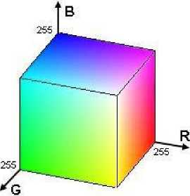
Fig.1. RGB Colour Cube
HSV HSL
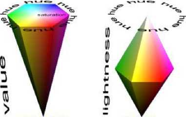
Fig.2. HSL/V Colour Cube
RGB model simplifies the design of computer graphics and it is the default colour space used in most applications [13]. RGB is not a suitable colour space for skin detection because the chrominance and luminance component are mixed. Moreover, it varies under different lighting condition [13]. However, this colour mixture components can be well separated in YCbCr. Besides YCbCr, HSV/I/L also works well for skin color detection.
In this space, H represents the Hue value while S is the Saturation value. These are the two components that are used to define a threshold to distinguish objects that have skin colour distribution [14]. Fig. 2 shows the HSV and HSL color space.
Since each colour space has its own pros and cons, some studies have been done on using more than one colour space for skin segmentation. One of the example is by using YCbCr - YU'V or RGB - YU'V colour space which have been done [15]. The YU'V colour space is used to filter out the noise pixels by calculating “ch”. Besides that, another method that uses three colour spaces for skin segmentation is RGB-HS-CbCr [16].
Although skin colour segmentation is fast and can detect human face with different angle, problem arises when background colour is within the range of the skin colour. It will segment out the background image. Some simple methods were proposed to eliminate some amount of non-face object such as box ratio and eccentricity [17]. However, these two methods cannot eliminate all nonface regions.
Besides skin colour segmentation, human face can also be detected using edge orientation image. According to [18], the edge orientation map is first extracted from a face model and then it is used to match against the edge orientation map of the input image. To locate faces that are larger or smaller than the input face, a pyramid model of edge orientation fields has to be built. Since this method uses only the edge orientation information, false detection usually occurs when image texture or edge frequency is high. This problem is then reduced in [19] with a fast face detection algorithm using skin colour information and orientation map matching. Another research is also done by using gray image for orientation matching [20].
Viola Jones [21] is also a very popular algorithm especially to look for fast face detection. However, only frontal face can be detected. This face detection algorithm is based on matching facial features. Four major ideas that make this algorithm very popular and works very well in real time are Haar features, integral image, AdaBoost and cascade structure. Rainer and Jochen [22] extended the basic set of Haar like features by a set of 45° rotated features. Besides that, to address the over-fitting problem due to lighting conditions, complex backgrounds and poses, Qiao and Guo [23] proposed a soft margin AdaBoost algorithm. A regularization term was introduced and the most effective weak classifiers are selected.
Many different research have been done on robotic vision by applying the knowledge of image processing. For an example, model based recognition in robot vision is done by [24]. They introduce an algorithm to recognize the identity, position, and orientation of randomly oriented industrial parts. Besides that, text detection and pose estimation is also done [25]. They presented two processes for robot vision, which is detecting the text from scene image, and the orientation of the text surface with respect the viewing axis of the camera mounted on the robot. Furthermore, face recognition using multiple face patterns obtained in various views for robot vision is also introduced in [26]. They developed a face recognition method based on the constrained mutual subspace method (CMSM) using multi view point face patterns attributable to the movement of a robot. Different functions added in robotic vision have different purposes.
Actuators are mostly implemented in real-time design for face tracking. The most basic need of actuator is to orientate the face region into the middle position. This can be only implemented with a moving camera. Moving camera is controlled with Pan, Tilt and/or Zoom. There are several research conducted with moving camera [2728]. Moving camera can always widen the field of view. However, it will lead to a dynamic background.
In this research, skin color segmentation with combination of three color space is used. Besides that, the idea of this research is for auto positioning where the data obtained from skin color segmentation is used to control the actuator mounted on the image sensor. It is also important to obtain images with high resolution. Few researches [29-30] have shown that they had successfully extracted human heart rate and beat lengths from video through colour magnification and motion magnification. These researches have brought a great improvement on the study of image processing especially used for medical diagnosis.
-
III. Methodology And System Design
This section describes the methodology and design of the complete system. Fig. 3 shows the hardware architecture of this system. The camera is mounted on the servo motor which can rotate in yaw and pitch direction. The software and hardware processing is done in MATLAB platform. The computer is the hub for software processing. Once the system begins, the camera will be adjusted to default position which is in the middle. At this position, the torque applied is almost zero. Once the processing for face detection is done, the microcontroller will process the data to control the servo motor to centralize the face region.
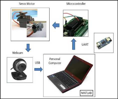
Fig.3. Hardware Architecture
Fig.4 shows the overall system flow chart of the research. The system flow can be divided into 5 major stages: initialization, face detection, face localization and center comparison, serial communication and position adjusting.
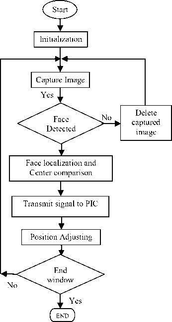
Fig.4. System Flow Chart
Stage 1 is the initialization stage. At this stage, the position angle for both servo motors are set to 90 °, which adjusts the servo motor to be at middle position. Webcam is then interfaced with MATLAB to acquire image. The colour space chosen is RGB (default) and the frame size is 320 X 240 in pixel dimension. Besides that, the baud rate for UART serial communication is set to 9600. Once the program is executed, the webcam will capture the image and stores it into MATLAB file.
The next stage is stage 2 which is Face Detection. The image obtained from Stage 1 will be processed by MATLAB in order to detect human face. If there is no human face found, this image will be deleted and a new image will be captured. Stage 3 is the Face localization and centering comparison. After the human face is detected, the location of the human face will be determined. The centroid of the detected human face is always compared with the center of the captured image, where x-coordinate is 160 and y-coordinate is 120. This is needed to decide what signal to be sent from MATLAB to PIC in order to control the servo motors in yaw and pitch direction.
Stage 4 is designed for serial communication. Signal sent from MATLAB to PIC is communicated through UART Serial Communication. Since UART works in asynchronous mode, thus the baud rate set for MATLAB and MPLAB must be equal, which is 9600. Besides that, UART can only send maximum of 8 bit at each time. Thus the PIC will receive the bits sent a few times. Finally, stage 5 is for Position Adjusting. Once the signal is received from MATLAB, PIC will process the signal and produce suitable PWM to rotate both servo motors. This will also change the position of the webcam which is mounted on servo motor. After the webcam position is adjusted, the detected human face becomes at the center of the image. Finally, if the window is chosen to be closed, the whole process will stop. However, if an opposite operation is performed, a new image will be captured and the whole process be repeated.
-
IV. Software Development
-
A. Face Detection
This section describes the software development in detail. The algorithm of face detection is shown in flowchart in Fig. 5. The image is captured by webcam in RGB colour space and with a frame size of 320 X 240 pixel dimension. Since the colour space chose for skin segmentation is RGB-HS-CbCr, so colour space conversion from RGB to YCbCr and RGB to HSV is done.
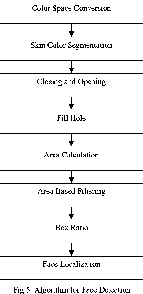
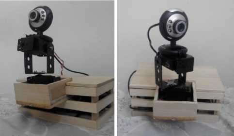
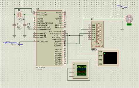
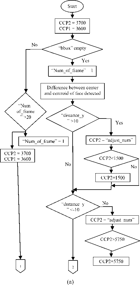
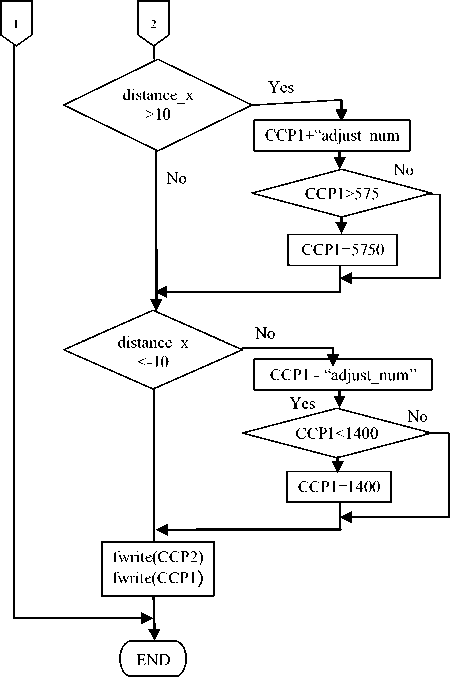
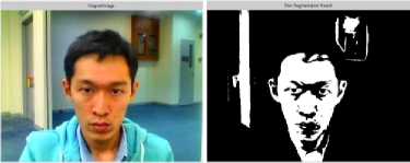
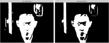
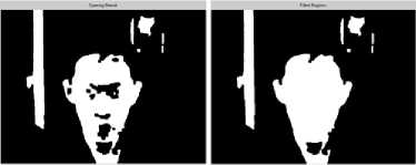
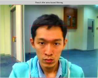
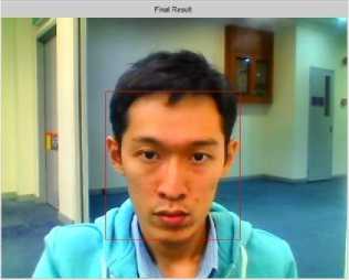
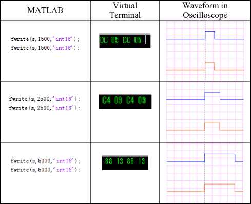
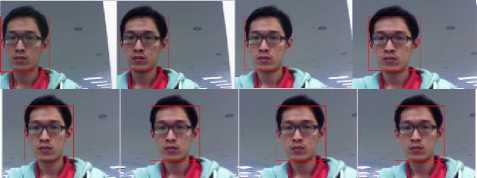
After colour space conversion is done, the next step is to segment out the skin colour region. According to [16], the skin threshold for RGB colour space is R>50, G>40 and B>20; max{R,G,B}-min{R,G,B}>10; |R-G|>10 and R>G and R>B or R>220, G>210, B>170,|R-G|≤15, B The next step is to apply closing operation to the image, which means dilation will be applied, followed by erode. The purpose of this closing operation is to eliminate any object that is found on non-face region. In this research, the object addressed is spectacles. The presence of spectacles may separate the human face into two different regions. Closing operation will allow the nearby pixels to merge together forming a new region. However, there are still some noise on image. Thus, opening operation is then performed. The structuring element object for closing and opening is a square with dimension of 7 X 7 pixels and 5 X 5 pixels respectively. After closing and opening are done, hole filling is then performed to fill in the missing pixel of the detected human face by using “imfill” function in MATLAB. This function fills in the holes within the connected line, which may help to merge the mouth and the eye into one region. After this stage, the connected region is then numbered using “bwlabel” function. This function will produce an output of the number of connected objects found. Besides that, this stage is also helpful when calculating the area of each connected objects as they are assigned with different number. Function “regionprops” is used not only to find out the area of the connected objects but also the location of each bounding box. After calculating the area of each connected object, area-based filtering is then performed. According to [31], if the area of the connected object is less than 26% of the largest area, that connected object will be eliminated. Supposedly the final result should locate the human face; however, there might be some background which has same colour, for example hand, legs and wall. A basic algorithm is proposed in order to reduce the small amount of non-face region, is the box ratio method [17]. According to box ratio method, the most favourable width to height ratio is within 1.1 and 0.4. Boxes which have the ratio outside this value will be eliminated. Besides that, boxes which have larger height and within this range, the height will be changed to 1.1 times the width. This can help to eliminate the neck region. After completing the above process, the face region can then be successfully detected. A. Structure Development This section reviews the hardware development used in this research. A prototype, which is shown in Fig. 6, was built for this system. There are two servo motors used, which are placed at top and bottom. The bottom servo motor will move left and right (yaw), whereas the top servo motor will move up and down (pitch). The webcam is just placed on the top servo motor. This allows the webcam to rotate according to the servo motor rotation. Fig.6. Structure Built B. PWM for Servo Motor Two servo motors are used to adjust the position of the webcam. The signal that the servo motor received is in PWM with frequency of 50Hz. PIC16f877A is used to process the signal sent by MATLAB and to produce PWM to servo motors. One weakness about PIC16f877A is that its PWM module cannot scale down its frequency to 50Hz when 20MHz crystal is used. Thus, this problem is solved by using compare module in PIC. There are 2 modules associated with the compare section – the CCP module and the Timer 1 module. The basic idea is that Timer 1 acts as a clock where the value change according to time; whereas CCPR1 and CCPR2 act as register which stores the value. The CCP and TMR1 register is composed of two 8-bit registers (high bit and low bit) that forms a 16-bit register. The high 8-bits are named as CCPRXH register or TMR1H whereas the low 8-bits are named as CCPRXL or TIMR1H register. When the value of Timer 1 meets the value stored in CCPR1 or CCPR2, an interrupt will be triggered. In short, the value assigned to CCP can adjust the pulse width and the period of PWM. First at all, when CCPR1 is equal to TMR1, interrupt CCP1IF is auto set to “1” and jump to the interrupt function. Timer 1 is then compared with 20ms. If the value is more than 20ms, Timer 1 will be set to 0 manually and count again so that the next PWM can be created. Pin RC2 checks whether it is high (1) or low (0) before assigning value to CCP. When it is found to be low, pin RC2 will be set to high and CCP will be assigned with value transmitted by UART. However, if it is found to be high, pin RC2 will then set to be low and CCP will be assigned to 0.02 second. In short, value transmitted by UART will determine how long is the pulse width. Since the value assigned to CCPRX determines how long is the pulse width of PWM and also which angle the servo motor rotates, Table I is tabulated to show the available value range stored in CCPR1 and CCPR2 after testing. Since 20MHz crystal is used and prescaler is set to 1:2, the cycle of the timer1 is Tcy = 2*(1/20000000)*4 us = 2*0.2us= 0.4us. This means that when the value of timer1 increases by 1, it takes 0.4us. So timer1 take 20ms to reach value of 50000. From table I, 1500 is equal to 0.6ms and 5750 is equal to 2.3ms. Table 1. Available Value Range Stored in CCP1 and CCP2 Servo motor 1 (CCPR2) Servo motor 2 (CCPR1) Lowest value 1500 1400 Highest value 5750 5750 Value for middle position 3700 3600 C. Transmiting and Receiving Signal Through UART Coding is translated to transmit signal from MATLAB to PIC via UART serial communication. In MATLAB function “fwrite” is used to transmit signals. It is used twice every time because there are two servo motors need to be controlled. After the signal is transmitted, it will be received by PIC. In MPLAB coding, function “UART_Data_Ready” is used to check the start bit of the signal sent. Besides that, another function called as “UART_Read” is used to receive the 8 data bits of the signal. Proteus simulation testing is done before hand to check the integration of PIC code into circuit design. This is shown in Fig. 7. “COMPIM” is used to choose which COM port is used and helps to pair up the COM port of Proteus with MATLAB using Eltima software. Besides that, two tools are used, which are Virtual Terminal and oscilloscope. Virtual Terminal shows the signal sent in hexadecimal form, to check whether correct value is sent. Besides that, oscilloscope is also used to test the waveform of PWM produced for servo motor. This testing is done before implementing on real design. Fig.7. Simulation Testing for Signal Transmission and Receiving through UART D. Auto Positioning After the location of face detected is determined from stage 3, the values will be compared with center of the image and decide what signal should be sent to the PIC. The process flow is shown in Fig. 8. CCP1 and CCP2 are first assigned with 3600 and 3700 respectively so that the starting point of the webcam is at middle position. Output variable “bbox” is checked to make sure if it is empty. If it is empty, it means that no human face was found, then variable “num_of_frame” is checked to make sure if it is more than 20. If the value is not more than 20, then it will be increased by 1. On the other hand, webcam will be adjusted to middle position (starting point) again. This step is done so that when there is no human face detected for some period of time, the webcam will go return to original position. If “bbox” is not empty or if human face is detected, the “num_of_frame” will be assigned with value 1. Then, the centroid of the human face is calculated and difference between the center of the frame with the centroid is calculated. The different between both of the x-coordinated is assigned to variable “distance_x”, while the different between both of the coordinate_y is assigned to “distance_y”. (b) Fig.8. Flow Chart of Auto Positioning It is difficult to auto position when the centroid of the face has exactly same coordinate with the middle point of the frame, (160,120). So, the middle point is expanded where the different between distance_y and distance_x is not more than 10 pixels, then the servo motor will stop changing position. This is why “distance_y” is first checked whether it is more than 10 or less than -10. If the distance_y is found to be more than 10, this means that the centroid of the face is below the center point, so CCP1, which control the servo motor 2, will be subtracted by constant variable “adjust_num”. This can adjust the motor to tilt. Besides that, if the distance_y is found less than -10, CPP1 will be added by variable “adjust_num”. Since the available value range for CCP2 is from 1500 to 5750, so after adding or subtracting the CPP1 with “adjust_num”, the output will be checked to make sure it does not exceed the range. If the value is outside the range, the highest value (5750) or lowest value (1500) will be final output. Same method is also applied to CCP1 but only the available value range is change from 1400 to 5750. Finally, both CCP1 and CCP2 are sent to PIC by using “fwrite” function. Testing was made to find a suitable value for variable “adjust_num”. The value tested starts from 10 to 50. It was found that the suitable value is 30. A. FaceDetection Fig. 9(a) to Fig. 9(f) shows the result of face detection for every step. Results include skin colour segmentation, closing, opening, holes filling and box ratio. Fig. 9(h) shows that human face is successfully segmented and non-face regions are also eliminated using box ratio method. (a) Original Image (b) Skin Segmentation (c) Dilate (d) Erode (e) Opening (f) Filled Region (g) Result after area based filtering (h) Final result Fig.9. Results for Face Detection B. Proteus Simulation Table II shows the results shown by virtual terminal and oscilloscope when different input values are sent to PIC. From the table, when input values is 1500, virtual terminal shows result of “DC 05”, which means “05 DC”, the hexadecimal form of 1500. This shows that the LSB bit will send first followed by MSB. Besides that, the waveform recorded from oscilloscope shows that the pulse width is around 0.6ms since the scale is adjusted to 0.5ms per division. Other values were also tested and it returns a positive result. Table 2. Result Shown at Virtual Terminal and Oscilloscope When Different Input Values Are Sent C. Auto-Positioning Fig. 10 shows results of auto positioning. The picture starts from the top left where original human face detected is on left hand side. Servo motors tries to adjust the position after performing all algorithms as discussed in this paper. It can be seen that the human face is moved slowly to the center. The final image shown that the face detected is located at the center of the image. Besides that, if no face is detected after 20 frames, the webcam will move to original position again and look for human face again. Fig.10. Results for Auto Positioning D. Value for Variable “Adjust_Num” Table III shows the results shown when different values are assigned to variable “Adjust_Num”. From the result, the final value decided is 30 since there is no overshoot problem and it performs faster when compared to the value 10 and 20. Table 3. Available Value Range Stored in CCP1 and CCP2 Value of “adjust_num” Result 10 Can move to center point but in very slow speed 20 Can move to center point 30 Can move to center point 40 Can sometime move to center point, but sometime overshoot 50 Overshoot problem often occurs This research is conducted to design a face detection with auto positioning for robotic vision. This real-time system is very useful to be implemented on robots that requires an advanced vision system. This design utilizes the face technology to determine the location of face where it uses a combination of two color space which are YCbCr and HSV. The result obtained from face detection stage is then used to control two servo motors which rotates in yaw and pitch direction. For every detected face in a frame, the motors will orientate to ensure that the face is returned to the middle of the screen. This will make sure that the face region is always within the field of view. Results shows that this system delivers an acceptable performance for skin sample that has similar background image under the same threshold. AcknowledgementV. Hardware Development
VI. Result and discussion
VII. Conclusion
References Face Detection and Auto Positioning for Robotic Vision System
- Down, M.P and Sands, R.J. Biometrics: An Overview of the Technology, Challenges and Control Considerations. Information Systems Control Journal, Volume 4, 2004.
- http://www.irobot.com/us/learn/commercial.aspx.
- Luo, R.C., Chen, C., and Pu, Y. Internet Based Remote Supervisory System for Tele-medicine Robot Application. IEEE Workshop on Advances Robotics and its Social Impact, 2009, 153-158.
- Muralindran Mariappan, Vigneswaran Ramu, Brendan K.T.T, Thayabaren Ganesan, Manimehala Nadarajan. Design and Development of Communication and Control Platform for Medical Tele-diagnosis Robot (MTR). International Journal of Networks and Communications, 2013, 3(1): 12-20.
- Mohamed, A.S.S., Weng, Y., Ipson, S.S., Jiang, J. Face Detection based on Skin Colour in Image by Neural Networks. International Conference on Intelligent and Advanced System, 2007, 779-783.
- Kovac J, Peer P, Solina F. Human skin color clustering for face detection. In: IEEE Region 8 International Conference on Computer as a Tool, 2003, pp. 144 –148.
- Shahrel A Suandi, Shuichi Enokida, Toshiaki Ejima. EMo Tracker: Eyes and Mouth Tracker. Proceedings of Indian Conference on Computer Vision, Graphics and Image Processing, IAPR Sponsored Conference, India, Kolkata, 2004, pp. 269-274.
- Zaher Hamid Al-Tairi, Rahmita Wirza Rahmat, M. Iqbal Saripan, and Puteri Suhaiza Sulaiman. Skin Segmentation Using YUV and RGB Color Spaces. Journal of Information Processing Systems, 2013, 10(2): 283-299.
- Bojic. N and K. K. Pang. Adaptive skin segmentation for head and shoulder video sequence. SPIE Visual Communication and Image Processing. Australia: Perth, 2000.
- Kukharev G. and A. Nowosielski. Visitor identification elaborating real time face recognition system. In Proc. 12. 2014.
- Chai and Ngan. Face segmentation using skin-color map in videophone applications. IEEE Trans. on Circuits and Systems for Video Technology, 1999, 9(4): 551-564.
- Jorge Alberto Marcial Basilio, Gualberto Aguilar Torres, Gabriel Sanchez Perez, L. Karina Toscano Medina and Hector M. Perez Meana. Explicit Image Detection using YCbCr Space Color Model as Skin Detection. Applications of Mathematics and Computer Engineering, 2010, pp 124-128.
- Singh, S., Cauhan, D.S., Vasta, M. and Singh, R. A Robust Skin Color Based Detection Algorithm, Tamkang Journal of Science and Engineering, Volume 6, Issue 4, 2003, 227-234.
- Muralindran Mariappan, Manimehala Nadarajan, Rosalyn R. Porle, Vigneswaran Ramu and Brendan Khoo, A LabVIEW Design for Frontal and Non- Frontal Human Face Detection System in Complex Background, Applied Mechanics and Materials, Volume 490-491, 1259-1266, 2014.
- Fan Hai Xiang and Shahrel Azmin Suandi. Fusion of Multi Color Space for Human Skin Region Segmentation. International Journal of Information and Electronics Engineering, March 2013, 3(2):172-174.
- Sayantan Thakur, Sayantanu Paul, Ankur Mondal. Face Detection Using Skin Tone Segmentation. 2011 World Congress on Information and Communication Technologies, 2011, pp. 53-60.
- Rafel C. Gonzalez, Richard E Woods. Digital Image processing (Second edition). Prentice Hall, 2002.
- Bernhard Froba and Christian Kublbeck2001. Real-Time Face Detection Using Edge-Orientation Matching. 3rd International Conference on Audio and Video Based Biometric Person Authentication, 2001, pp78-83.
- Li Bai and LinLin Shen. Face Detection by Orientation Map Matching. International Conference on Computational Intelligence for Modelling Control and Automation, Austria, Feb 2003.
- Linlin Shen and Li Bai. Face Detection in Grey Images Using Orientation Matching. School of Computer Science & IT University of Nottingham. Proceeding 17th European Simulation Multiconference, 2003.
- Viola P. and M. Jones. Rapid Object Detection using a Boosted Cascade of Simple Features. IEEE Conf. on Computer Vision and Pattern Recognition, 2001, Kauai, Hawaii.
- Rainer Lienhart and Jochen Maydt. An Extended Set of Haar-like Features for Rapid Object Detection, 2002, IEEE ICIP. 1:900-903.
- Qiao R.Y and Y.Guo. Face Detection Using Soft Margin Boosting. Image and Vision Comuting. New Zealand Conference, 2002, pp.157-161.
- Roland T. Chin and Charles R. Dyer. Model-Base Recognition in Robot Vision. Computing Surveys, March 1986, 18(1): 67- 108.
- Marius Bulacu, Nobuo Ezaki and Lambert Schomaker. Text Detection and Pose Estimation for a Reading Robot. Mobile Robots Motion Planning, New Challenges, pp.39-62.
- Kazuhiro Fukui and Osamu Yamaguchi. Face Recognition Using Multi-viewpoint Patterns for Robot Vision. 11th International Symposium of Robotics Research, 2003, pp.192-201.
- Guha Balakrishnan, Fredo Durand and John Guttag. Detecting Pulse from Head Motions in Video. IEEE Conference on Computer Vision and Pattern Recognition, 2013, pp 3430 – 3437.
- Masakazu Matsugu, Kan Torii, Yoshinori Ito, Tadashi Hayashi and Tsutomu Osaka, Face Tracking Active Vision System with Saccadic and Smooth Pursuit, IEEE Conference on Robotics and Biomimetics, China, 2006, pp 1322- 1328.
- Yuji Nishina, Joo Kooi Tan, Hyoung Seop Kim and Seiji Ishikawa, Development of Autonomous Robot for Face Tracking, International Conference on Control, Automation and Systems, Seoul, 2007, pp 1178-1181.
- Hao-Yu Wu, Michael Rubinstein, Eugene Shih, John Guttag, Fredo Durand and William Freeman. Eulerian Video Magnification for Revealing Subtle Changes in the World. Medical Measurements and Applications (MeMeA), 2014 IEEE International Symposium on, 2012, pp 1-4.
- Thu-Thao Nguyen. Real-Time Face Detection and Tracking. School of Electrical and Computer Engineering of Cornell University, December 2012.
