Fast Width Detection in Corridor Using Hough Transform

Author: Mehrdad Javadi, Mehdi Ebrahimi
Journal: International Journal of Image, Graphics and Signal Processing(IJIGSP) @ijigsp
Article in issue: 12 vol.4, 2012.
Free access
For many robotics and smart car applications it is vitally important to calculate the width. The present paper proposes a new approach for finding the width of a corridor within a constructed image frame that would keep a robot on a safe track away from walls. The main advantage of this approach is less computation time and hence faster response for path recognition. In this new approach, the Hugh Transform technique is also used as the basis of the provided algorithm. Within the determination of corridor width, in order to avoid the accident in the future researches, some approaches such as identify open space, modeling and reconstruction of three-dimensional space, can also be used.
Vision based, Width detection, Navigation, Hough transform, Robot
Short address: https://sciup.org/15012513
IDR: 15012513
Text of the scientific article Fast Width Detection in Corridor Using Hough Transform
Published Online November 2012 in MECS
Nowadays, vision, based on image processing provides a powerful tool for autonomous robot motion and navigation. Compared to other methods and sensor techniques, the trend based on vision is well received in robot navigation and is a subject of interest for researchers and intense studies were done in this regard. One of its reasons is the ability to extract detailed data from robot operating environment for which the other methods are even incapable. In past decades vision based recognition methods in robot motion and navigation were deployed mostly in enclosed regular environments (corridors), thus there is still no suitable solution for the issue of robot movement in irregular corridors.
In this article we would develop a simple, novel strategy for calculating corridor width using just the image data captured by a simple camera. Depth and width estimation is very difficult in Monocular Vision [1].Although, the sonar and laser techniques, which are the basics of the exploration techniques, were used many times, but they do require additional sensors and entail more expenses. Therefore, in this research which its basis is on the image processing, considering its strengthening and weaknesses, a new method to calculate the width of a regular indoor hallway (corridor) is proposed. Following, an overview of the work done in this area will be referred.
-
II. BACKGROUND
One of the most important and fundamental issues in vision based robots movement and navigation, is the environmental image processing which in it, robot is moving to identify the particular characteristics. Also one of the main issues in image processing, is the recognition of motion path and navigation, barriers, walls and objects within the image. The objects or an image is being formed of a group of points, edges and lines which are connected together.
Recognition of the lines is one of the main problems in image processing. A general method to solve it is Hough transform. The Hough Transform method, named after Paul Hough [2] who invented it in 1962; it is a general and powerful method for edge and lines recognition. In order to define a line, the Cartesian coordinate system is shifted to a parametric coordinate system .Use of Hough transform method is based on the gradient of line and its parameters. Later, in 1979, Duda and Hart, proposed the natural shape of line to prevent infinite range of parametric space as the algorithm DHT [3]. Previously, based on the random sampling technique, Fischler and Bolles presented the Random Sample Consensus (RANSAC). The RANSAC algorithm [4] randomly selects two edge pixels each time and then other edge pixels are used to test whether the line determined by the two edge pixels is a true line in the image. The probability of two randomly picked edge pixels coming from a true line in an image is low and it degrades the efficiency of the RANSAC.
Later, in 1997, Kaelviaeinen and Hirvonen proposed a connective randomized Hough transform (CRHT) [5] which improves the RHT by exploiting the connectivity of local edge pixels.
The effectiveness and efficiency of the CRHT heavily depends on the connectivity of neighboring edge pixels. Problems may arise if the testing image is in the presence of distortions and noises. To alleviate these problems, Kyrki and Kaelviaeinen proposed an extended connective randomized Hough transform (ECRHT) [6]. The ECRHT also uses local Information, to improve RHT. Basically, the RHT, CRHT, and ECRHT belong to the type of HT-based methods.
In 2001, Teh-Chuan Chen and Kuo-Liang Chung, presented a new Randomized Line Detection algorithm in their paper, called RLD. The proposed RLD [7] first randomly picks three edge points in the image and uses a distance criterion to determine whether there is a candidate line in the image. After finding the candidate line, it follows an evidence-collecting process to further determine whether the candidate line is the desired line.
A gradient-based and region-based line extraction algorithm, first developed by Burns[8] in 1986. Later in 1990, P. Kahn, L. Kitchen, and E. M. Riseman, developed a Fast Line Extraction algorithm (FLF) [9] which was based upon the Burns' work.
In 1998, Vassallo [10], presented a simple and rapid method to identify the lines in the corridor and to calculate the endpoint. In this method, there is a good contrast between walls, corridor floor and only one edge of the corridor. Also in an article, another method for corridor Line detection and robot navigation was proposed by Wenxia Shi, and Jagath Samarabandu [11]. The proposed method consists of three low, medium, and high level processing stages which correspond to the extraction of image features, the formation of hypotheses, and the verification of hypotheses using a feedback mechanism, respectively. In this method, it is also used the FLF algorithm to extract the gradientbased and region-based lines. There are several vision based articles and algorithms related to distinguish of lines and edges [12-19].
-
III. PROPOSED METHOD
One of the most important, primary and necessary tools for implementing the movement of autonomous inspection robot is divided into two main sections, as follows:
-
A. Hardware( Figure 1)
-
1. Machine or car: The main components of this machine are the car chassis, wheels, engine, electrical power supply and battery.
-
2. Sensor: A digital camera device which installs on the machine, imaging environment and sends the images to the computer.
-
3. Computer: A computer with a powerful processor which sets on the machine and processes the input images through an operating software.
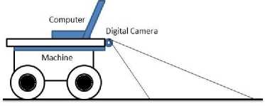
Figure 1.General view of an inspection robot
-
B. Software:
An operational software which processes and analysis the receive images and determines the motion path and decision of th robot for the next movement. In figure 2, the main components of the software are shown as:
-
1. Blackboard: includes all data(Assumptions, facts and deductions)
-
2. Sensor Handler: requesting and receiving
-
3. Drive Controller: sending all movement
-
4. Differential: image processing to determine
environment image from camera
commands to machine
barriers, the movement end-point, calculating the distance between wall and the corridor width, location, drawing the road map and finally, decision for the next move of the robot.
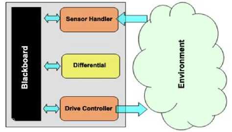
Figure 2.General view of robot software
Proposed method to detect and measure the width of the corridor consists of four main parts:
-
• Image pre-processing
-
• Hough Transform
-
• Extraction of the desired lines and edges
-
• Calculation of corridor width
-
a) Image Pre Processing
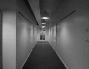
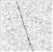
The first step to preprocess an image is to read it and to resize it should the image be large formatted so as to minimize the processing time. In order to reduce the glare, the RGB image is converted into black and white (Figure 3-(a)) for a sample corridor [20].
(a)
(b)
(c)
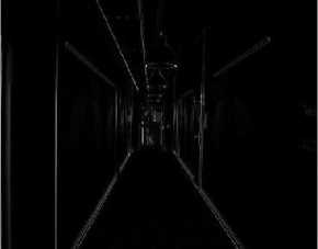
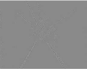
Using a low-pass Gaussian filter the image previously constructed is superimposed on the image. The filter eliminates the possible noises in the images. In order to further reduce noises and maintain higher image resolution the Gaussian function is differentiated based on X and Y component. The image is filtered based on derived components fx and fy and is calculated using the magnitude gradient function mag(grad f) = sqrt( fx2 + fy2) (1)
which indicates the edge intensity in the image (figure 3-(a),(b)). Pixel brightness within the image is of utmost importance for recognition of lines and may cause deviation and error in the image during the recognition phase. Therefore pixel brightness levels above 1 are assigned the unity value and for those less than 1, the null value is assigned. In another words, the brightness intensity of pixels within the image is assumed to be constant. The image quality and noise reduction could be further improved by eliminating singular pixels that are not adjacent to any other pixels. Provision of adequate image contrast would ensure the needed edge extraction from the image. In order to obtain 45 degrees inclined lines, a 45 degree filter is deployed over the image for edge recognition. This would further increase the accuracy in edge recognition using the lines obtained through this algorithm. The outcome of applying such filter to an image is shown in Figure 3-(c). 45 degree lines are reliable characteristics for both the image and corridor size [21].
-
b) Hough Transform
Named after Paul Hough who invented the method in 1962, it represents a general and powerful method for edge recognition. In order to define a line, the Cartesian coordinate system is shifted to a parametric coordinate system [22]. Therefore the Hough transform furnishes a method for finding and linking various portions of an image. Standard Hough Transform was used within MATLAB environment to extract the desired lines from the edges recognized. The present research had made use of MATLAB functions and references [23] and [24] can provide excellent information on line extraction using Hough method. In using Hough Transform to recognize lines, line parameters are given in polar coordinates as follows:
X sin θ + Y sin θ = ρ
Variable ρ denotes distance from the origin normal to the line. Θ is the angle between the X-axis and vector ρ. Hough transform generates a parametric matrix whose rows and columns are ρ and θ respectively. Figure 4 illustrates the main concepts relevant to Hough transform [25].
(c)
(d)
(e) (f)
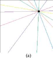
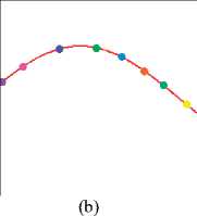
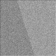
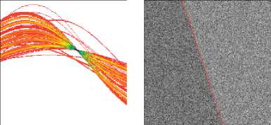
Figure 4.Main Concepts associated with Hough Transform. (a) A sinoidal line in Hough space by which all lines could be drawn. (b) Each point within Hough space maps a line in real space. Lines within real space, given different colors, correspond to similar color points in sinoidal depiction. (c) Original image with noise. (d) Noise reduction using Sobel Gradient Filter. (e) Hough Transform produced from gradient image. (F) Line defined with maximum point in Hough
Transform. (John C. Russ., The Image Processing handbook [25])
The parametric matrix described when using Hough () function in MATLAB, is called the H matrix. It is a two dimensional that indicates the straight lines found within the given image (figure 5(a)).
(a)
(b)
(c)
Figure 5. (a) h ough t ransform (b) p eak p oint identification (c) a ll lines extracted from Hough Transform
The first step when deploying Hough transform for line recognition is to identify the peak point connections. Fining a meaningful collection of distinctive peak points within Hough transform is hard. Given the quantitative determination of digital image space and Hough transform parametric space along with the fact that the image edges are not thoroughly straight, Hough transform peak points are usually located in more than one cell within Hough transformation matrix (Figure 5(b)).
Thus following the identification of a set of peak points within Hough transform, the goal would be to find the non-null points within the image that contributed in forming of peak points. Pixels connected to the locations that have been found using Hough pixels, must be grouped into line segments and the ends of the lines must be specified. At this stage the start and end points extracted from the resulting lines are stored in a specific matrix. The points obtained have been shown in Figure 5(c).
-
c) Extraction of the Desired Lines and edges
As explained earlier, all straight lines within the image have been obtained using 45 degree filter, Hough transform, Gaussian Filter and its derivatives over the image along with detailed information including start point (point 1), end point (point 2), line angle (θ) and line magnitude (ρ) which are particular to the line.
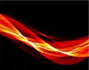
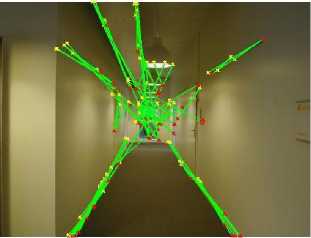
The most important goal in this project what to calculate and identify the width of the corridor. Therefore it is important to identify all the inclined lines formed from the wall edge margins and corridor floor. Using trial and error, it became clear that only those inclined lined whose theta is over or below 10 degrees, show the wall and floor edges. Figure 6 demonstrates inclined lines with angles lesser or greater than 10 degrees.
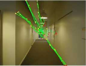
(a)
(b)
Figure 6.(a) Inclined lines with less than 10 degrees angle (b) Inclined lines with angles greater than 10 degrees
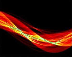
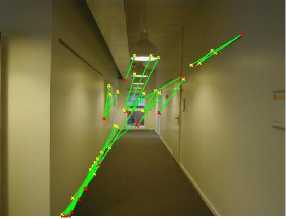
On the other hand as shown in figure 6, all inclined lines greater or lesser than 10 degrees angle are not needed since given the fact that the width of the corridor can be obtained from the lower half of the image, therefore there is no need for the data and inclined lines in the upper half of the image. Figure 7 shows inclined lines in the lower half of the image.
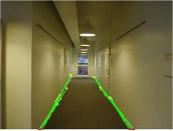
Figure 7.inclined lines in the image lower half
-
d) Calculation of corridor width
Corridor width calculation needs not to be extremely accurate since the robot that will be using these data would always maintain clearance from adjacent walls based on continuous image processing. The algorithm for calculating corridor width is as follows:
-
1. From image dead center, the image is divided into four parts (left, right, up and down) (figure 8)
-
2. Image is scanned from bottoms up ( both for points to the left and right of the image ), and the starting point for each line (Red X) is identified and placed in two LEFT_POINTS points and RIGHT_POINTS Matrices.
-
3. The starting points stored, are sorted in descending order based on the magnitude of proximity to the centerline (middle of the corridor) and placed in two LEFT_POINTS_SORT and
-
4. The endpoints in each of the above matrices are the initial starting points whereby the robot observes and identifies from left and right.
-
5. The end points are connected together and their size are calculated (figure 9).
RIGHT_POINTS_SORT Matrices.
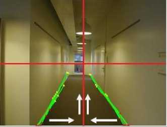
Figure 8. Partitioning the image into four lower and upper halves and left and right halves
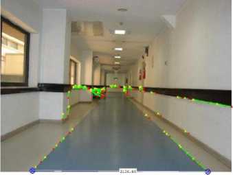
Figure 9. Displaying passageway width calculation in Milad Hospital of Tehran - Iran
In conclusion, the robot would adjust its distance to either left and right walls by matching its station point.
-
IV. Tests and Results
Since the corridor width calculation algorithm is done by robot, and is only applicable in orderly indoor environments (corridors), so all the tests have done in these environments.
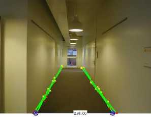
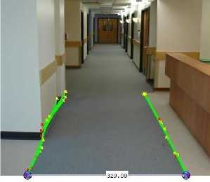
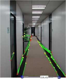
Figure 10. Displaying passageway width calculation
In all presented algorithms for image processing, it is possible to provide the final algorithm through using various trial and error tests. Given that the edge detection algorithms, filters and line detection algorithms, cannot adjust different positions in the image, a hundred per cent and its accuracy depends on objects location, clarity, light, edge intensity and noises in the image; so through manually special settings in proposed algorithms, the desired result can be taken. Until now, no specific method and algorithm in this field, has been designed to cover automatically all conditions in all images, a hundred per cent and each time running the algorithm, it is needed to manually alter the initial values by the operator.
The main input of the proposed algorithm, is included the images of the orderly indoor and covered corridors, which are almost tested by the program under the same conditions, and its output is a demonstration and calculation of the corridor width. The done calculation is based on real width and height of the image. When the robot is located in the corridor and moves in an actual route, the dimensions will be converted to the actual amount within the corridor.
The findings were applied to several corridors and the results were very good. These have been shown in Figure 10. for other sample corridors[26,27].
-
V. Conclusions and suggestions
Recently, within the topic "vision based robots navigation”, there is a special attention to the using of image processing due to the possibility of getting more detailed information about the environment. Environmental features such as closed or open, having open space, barriers, doors and windows ,etc. can be very important in the distinguish of the robot navigation. Therefore an algorithmic design, considering all environmental conditions, is the final goal of all researchers in this field. But now, as the topic "vision based robots navigation" is a neoteric issue, it is only applied in different cases, independently.
References Fast Width Detection in Corridor Using Hough Transform
- J. Michels, A. Saxena and A. Y. Ng. “High Speed Obstacle Avoidance using Monocular Vision and Reinforcement Learning”, Proc.22nd Int. Conf. Machine Learning, pp. 593–600,2005.
- P.V.C. Hough , “Method and Means for Recognizing Complex Patterns”, U.S. Patent 3,069,654, Dec. 18, 1962.
- R.O. Duda, P. E. Hart, ”Use of the Hough Transformation to Detect Lines and Curves in Pictures”, Commun. ACM, Vol.15, No. 1,pp. 11-15.1972
- M.A. Fischler and R.C. Bolles, (1981) “Random Sample Consensus: A Paradigm for Model Fitting with Applications to Image Analysis and Automated Cartography”, Commun. ACM, Vol. 24, No. 6, pp. 381-395,1981.
- H. Kalviainen, P. Hirvonen, “An Extension to the Randomized Hough Transform Exploiting Connectivity”, Pattern Recognition Letters, Vol. 18, No.1, pp. 77-85, 1997.
- V. Kyrki and H. Kalviainen ,“Combination of Local and Global Line Extraction”, Real-Time Imaging, Vol. 6, pp. 79-91, 2000.
- T.C. Chen, K.L. Chung, “A New Randomized Algorithm for Detecting Lines”, RealTime Img., Vol. 7, No. 6, pp. 473-481, 2001.
- J.B. Bums, A.R. Hanson, E.M. Riseman, “Extracting straight lines”, IEEE Trans. Pattern AnaL Machine Intell., vol. 8, no. 4, pp. 425-455, 1986.
- P. Kahn, , L. Kitchen, E.M. Riseman, “A Fast Line Finder for Vision-Guided Robot Navigation”, IEEE Trans. Pattern AnaL Machine Intell., Vol. 12, No. 11, pp. 1098-1102, 1990.
- R.F. Vassallo, H.J. Schneebeli, J. Santos-Victor, “A purposive strategy for visual-based navigation of a mobile robot”, Proc. Circuits and Systems , pp. 334-337, Aug. 1998.
- W.Shi, J.Samarabandu, “Corridor Line Detection for Vision Based Indoor Robot Navigation”,Canadian Conference on Electrical and Computer Engineering , PP.1988-1991, 2006.
- A.R. Brouwer, “Adaptive edge detection and line extraction for the Vision Survey System”, M.Sc. Thesis Eindhoven University of Technology , 1994.
- A. V. Nefian, G. R. Bradski, “Detection Of Drivable Corridors For Off-Road Autonomous Navigation”, IEEE Int. Conf. on Image Processing ICIP 2006, 3025 - 3028 2006.
- A.M. Zou, Z.G. Hou, M. Tan, D. Liu,“Vision-Guided Mobile Robot Navigation”, Proc. IEEE Int. Conf. Networking, Sensing and Control , pp. 209-213, 2006.
- P. Kahn, L. Kitchen, E.M. Riseman, “A fast line finder for vision-guided robot navigation”, IEEE Trans. Pattern Anal. And Machine Intell., vol.12, No.11, pp. 1098-1102, Nov. 1990.
- J. B. Burns, A. R. Hanson, E. M. Riseman, “Extracting straight lines”, IEEE Trans. Pattern Anal. Machine Intell., Vol. 8, No. 4,pp. 425-455, 1986.
- J. Samarabandu, W. Shi, “Corridor Line Detection For Vision Based Indoor Robot Navigation”, Canadian Conference on Electrical and Computer Engineering , 2006.
- J. Lee, C. D. CraneIII, “Road Following in an Unstructured Desert Environment Based on the EM (Expectation-Maximization) Algorithm”, SICE-ICASE International Joint Conference ,pp. 2969 - 2974 ,2006.
- H. S. Lho, J. W. Kwon, D. Chwa, S. K. Hong,"Vision-based corridor line detection using k-means algorithm” , International Conference on Control, Automation and Systems,PP.1052 – 1056,2007.
- http://acoustics.aau.dk/facilities/fac/corridor-3.html
- Rafael C. Gonzalez, Richard E. Woods: “Segmentation, Digital image processing”, (Pearson Prentice Hall, 3rd edition, 2008).
- G. Hamarneh, K. Althoff, R. Abu-Gharbieh , “Automatic Line Detection”, Project Report for the Computer Vision Course , By Image Analysis Group , Department of Signals and Systems, Chalmers University of Technology ,September 1999.
- R. O. Duda, P. E. Hart, “Use of the Hough transformation to detect lines and curves in pictures”, Communications of the ACM, vol. 15, January 1972, pp. 11–15.
- N. Aggarwal, W. C. Karl: “Line detection in image through regularized Hough transforms”, IEEE Transactions in Image Processing, vol. 15, no. 3, Mar. 2006.
- J. C. Russ , The image processing handbook ,CRC Press, Taylor & Francis Group, 5th ed., 2007.
- http://www.berkshireflooring.co.uk/casestudies.asp
- http://thingsinjars.com/post/112/office-corridor/
