Features of modeling the electron beam distribution energy for the electron-beam welding process

Author: S. O. Kurashkin, Yu. N. Seregin, A. V. Murygin, V. E. Petrenko
Journal: Siberian Aerospace Journal @vestnik-sibsau-en
Section: Technological processes and material science
Article in issue: 2 vol.21, 2020.
Free access
The energy distribution of the electron beam by means of application of various scanning paths, affects for-mation of the weld, which relates to the quality of the welded joints. Experimental studies, conducted by the au-thors of the article showed that scanning the electron beam in the form of a raster shape gives the best quality of welded joints; therefore, the trajectories of a classical raster and a truncated raster are proposed for the elec-tron beam welding process. When conducting research in this direction, the authors discovered the following regularity: with an increase in the scanning amplitude along the junction, the vapour-gas penetration channel transforms into a stable cavity, along the front wall of which the metal melts, and along the side walls it is trans-ferred to the tail of the weld pool. The discovered effect of the formation of a penetration cavity is to be investigated in electron beam welding of various materials and thicknesses. For this the necessary equipment is to be created, allowing to make scan-ning in the form of various rasters. To improve the quality of the electron beam welding process, trajectories of a classical raster and a truncated raster across the joint are proposed. For these scanning trajectories, analytical expressions and families of calculated characteristics of the electron beam energy density distribution over the heating spot are obtained. Modulation of the electron beam oscillation in the form of a truncated raster across the junction makes it possible to obtain a two-humped distribution of the beam energy on the surface of the part along the heating spot. The obtained characteristics allow a more meaningful approach to optimizing the pro-cess of electron beam welding of various materials.
Electron-beam welding, modelling, technological parameters, electron beam, optimisation, normal distribution law.
Short address: https://sciup.org/148321745
IDR: 148321745 | UDC: 621.791.722 | DOI: 10.31772/2587-6066-2020-21-2-266-273
Text of the scientific article Features of modeling the electron beam distribution energy for the electron-beam welding process
Introduction. The combination of energy and technological parameters of the process determines the quality of the weld in electron beam welding (EBW). The electron beam is a source of highly concentrated energy. The formation of deep penetration by a focused electron beam is achieved by means of formation of a vapor-gas channel in which the beam energy is transported. In this case, the welding seam gets a dagger shape with a characteristic mushroom formation in the upper part. The process of forming a weld in this case is oscillatory in nature with a periodic unstable melting channel. The mushroom-shaped expansion of the weld in its upper part is connected with periodic beam scattering on the metal vapor. Such a welding process is rarely used in practice except cases of through penetration. The pointed shape of the weld in the root part leads to the formation of root defects – voids arising from the displacement of liquid metal by the penetration channel. In order to avoid such defects, it is necessary to form a wider root part of the seam. The simplest way to form the radius at the root of the seam is to defocus the electron beam, which is used in practice mainly at installations with an accelerating voltage of 30÷60 kV.
The beam defocusing does not completely eliminate the root defects, in addition, the seam takes a shape close to a triangular one, the penetration depth decreases, deformation and tension occurs. Therefore, the defocusing of the electron beam is used only for EBW products of small thickness [1].
To prevent root defects, it is necessary to form a paro-dynamic channel with a sufficiently wide lower part. From the technical side, the most effective way of influencing the formation of a penetration channel is to oscillate an electron beam on the surface of the welded product. The current trend in the development of welding technology is to use complex reamers to form welds with a given cross-sectional shape. Illustration of an example of such a development, executed by Steirgerwald Strahltechnik company, is shown in fig. 1. Application of digital signal generators allows to create rasters of any shape with a fairly high resolution of up to 24 bits, which opens up great opportunities in the field of heat treatment, welding and soldering, and also plays a key role in solving the problem of pointing to the joint [2].
The technique for choosing the shape of the electron beam scan has not yet been developed. At the same time, a rather large amount of experimental data has been gathered [3]. The following beam scans are most widely used: longitudinal [4], x-shaped [4–6], circular and elliptical [6–9], arc and staple [10–13]. Sweep amplitudes usually vary between 1–3 mm.
Electron beam welding with the rotation of the electron beam along a circular path allows to gain a significant reduction in root defects and peak formation, however, since the power density in the central part of the heating zone is small, application of circular scanning leads to a decrease in the penetration depth compared to a fixed beam electron beam welding.
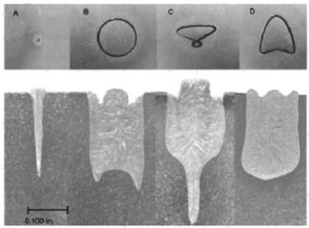
Fig. 1. Influence of the beam scanning trajectory on the weld cross-section: A – without scanning; B – circle; C – eight; D – arrowhead
Рис. 1. Влияние траектории развертки пучка на поперечное сечение сварного шва: А – отсутствие развертки; В – окружность; С – восьмерка; D – наконечник стрелы
The disadvantage of a circular sweep of the electron beam is also the difference in the directions of the beam at opposite edges of the weld. At the same time, on one of the edges, the direction of the beam motion coincides with the direction of the welding speed, and on the other side, it is opposite to it, which can lead to uneven formation of the weld.
In [14], the authors developed a new scanning path based on energy input. The study suggests applying trajectory instead of a contour to the beam control module along which the beam follows. As a result, the nominal energy density and modulation function are experimentally obtained, what makes it possible to determine the optimal input energy. However, this method of determining energy, proposed by the authors, is energy and resource consuming. Illustration of such a development is shown in fig. 2.
penetration cavity leads to degassing of the welding pool and a decrease in porosity. By reducing the proportion of energy, spent on the evaporation of the material, the penetrating ability of the EBW process increases [1].
It is advisable to study the effect of the formation of a penetration cavity when welding various materials and different thicknesses. For this, equipment should be created, which realizes scanning in the form of various rasters. In this paper, three types of scanning are considered: a classical raster, a sinusoidal raster, and a truncated raster. The objective of this study is to obtain the density of the energy distribution of the scanning electron beam on the surface of the part along the heating spot. It characterizes the distribution of energy in the weld pool.
The energy distribution in an electron beam is usually described by a normal law, which is characterized by a density probability in the form [17]:
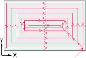
Fig. 2. New trajectories for melting a rectangular area
f ( x ) = -
■ V2-n
■ exp
^^^^^^»
( x - m ) 2 2 -3 2
Рис. 2. Новые траектории для плавления прямоугольной области
In [15], experimental studies on the application of various electron beam scans with the aim of the qualitative formation of welded joints are presented. The influence of the following scans was studied: circular and elliptical, x-shaped, zigzag, gimlet, raster, triangle, rowing with oars along isotherms. Studies have shown that the best scan for the quality of the formation of the weld is a raster in which the beam is scanned in the coordinate combined with the junction of the welded product according to a unilateral saw tooth law, while the beam moves from the front of the bath to the tail according to a linear law with subsequent instant return to the front. Such a scan facilitates the transfer of molted metal to the tail section of the weld pool. During one scanning along the joint, 16, 32 or 64 scans across the joint along a bilateral sawtooth path are performed. The scan period along the junction is 1–2 ms. More detailed studies with scanning in the form of a raster revealed that with an increase in the scanning amplitude along the joint from 5 mm when welding small thicknesses to 15 mm when welding medium thicknesses, the gas-vapor channel transforms into a stable cavity over the entire penetration depth [16]. The shape of the cavity was fixed by abrupt discontinuing the welding process by switching off the accelerating voltage.
Mathematical modeling of the electron beam energy distribution . In fig. 3 a diagram of electron beam welding during scanning as a raster is presented. The form of the weld obtained has almost parallel walls and a significant radius in the root, what allows root defects to be eliminated, and instability of the penetration depth is reduced by 3–4 times. The openness and stability of the
where x is the coordinate along the abscissa axis, m is the mathematical expectation, and σ is the standard deviation, characterizing the diameter of the electron beam, and the concentration of the energy in it. This value is determined by the electron-optical system of the gun and its focusing system. It depends on the welding current and is usually determined in the range of σ = 0.05–0.5 mm. The smaller the diameter of the electron beam, the more high-quality beam the gun forms.
In order not to take into consideration the specific value of the standard deviation in the construction of the characteristics of the density of energy distribution over the heating spot, we introduce the dimensionless coordinates and amplitudes of the beam scanning along these coordinates:
У = y
where y is the coordinate along the joint, σ standard deviation, y is the dimensionless coordinate along the joint. In the system of dimensionless coordinates σ = 1
X = x , (3)
where x is the coordinate across the joint, x – is the dimensionless coordinate across the joint.
A = A ,
where A is the amplitude, A – is the dimensionless amplitude.
It is known that the maximum ordinate of the normal distribution (1), is equal, corresponds to the point x = m ; as the distance from point m increases, the distribution density decreases. The centre of symmetry of the distribution is the scattering centre m. This is clear from the fact that when the sign of the difference ( x–m ) is reversed, expression (1) does not change. If the scattering centre m is changed, the distribution curve will shift along the ab-
scissa without changing its shape. The scattering centre characterizes the distribution position on the coordinate axis [9]. Therefore, by changing the scattering centre according to the corresponding law, one can obtain the energy distribution density along the corresponding coordinate.
Energy of an electron beam [18]:
W ( x , y ) = U ■ I ■ J J W ( x)W ( y ) dxdy , (5)
-J - J where U is the accelerating voltage, I is the beam current, W (x) and W (y) are the normalized energy distribution functions along the corresponding coordinates,
J W ( x ) dx = 1, J W ( y ) dy = 1.
-J -J
Next, let us consider each scan in more detail. Scanning is conducted in the form of a classic raster, while the movement along the coordinate across the joint is carried out on a two-sided saw, described by a piecewise linear function:
x = k · t + m ,
where t is an independent variable, k and m are some numbers, and in case, when, k = 1, for a time t = [–1; 1] for a period T , this graph will be presented in the form of a triangular function (fig. 4).
It is known that when changing the mathematical expectation in formula (1), the graph shifts relative to its center. Consequently, instead of mathematical expectation, it is possible to substitute the necessary expression, for a raster it is a linear function. It is also necessary to integrate the resulting expression.
The following formula is obtained [18]:
W ( x ) = J--=
-1 c^ V2 ■n
where, Ax e [1;10], x e [ - 15; 15], k = 1, m = 0, x is the dimensionless coordinate along the joint, Ax is the dimensionless amplitude across the joint, and σ is the standard deviation.
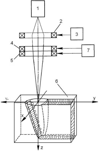
Fig. 3. A scheme of electron-beam welding when scanning in the form of a raster:
1 – electron beam gun; 2 – focusing system; 3 – focus current source; 4 – deflection coil; 5 – deflection coil; 6 – product surface; 7 – beam scan generator
Рис. 3. Схема электронно-лучевой сварки при сканировании в виде растра:
-
1 – электронно-лучевая пушка; 2 – фокусирующая система;
-
3 – источник тока фокусировки; 4 – отклоняющая катушка;
5 – отклоняющая катушка; 6 – поверхность изделия; 7 – генератор сканирования пучка
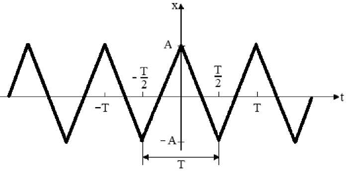
Fig. 4. Graph of successive triangular pulses
Рис. 4. График последовательных треугольных импульсов
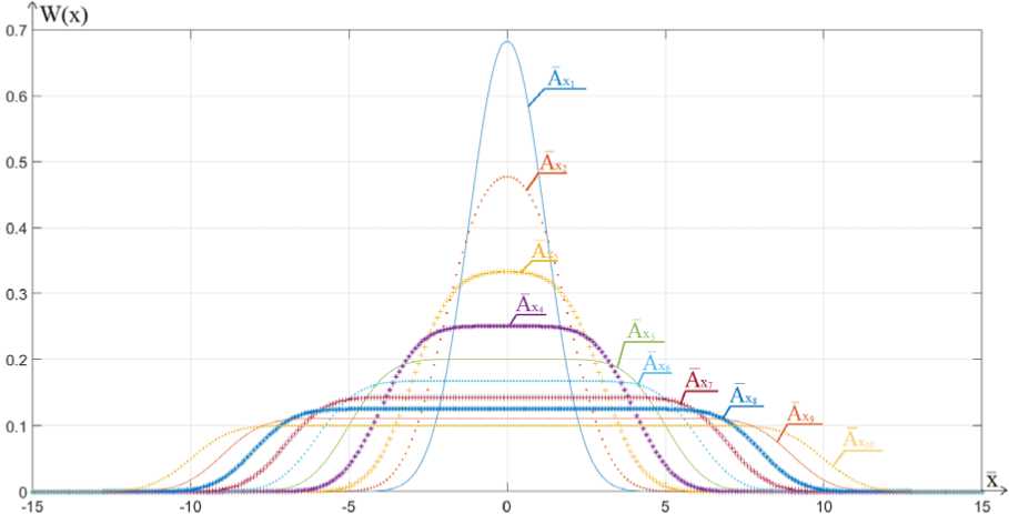
Fig. 5. Energy distribution on the surface for the case of a scanning trajectory in the form of a truncated raster:
й = 1; A 2 = 2; A X 3 = 3; Aй = 4; Ай = 5; Ай = 6; Ax; = 7; A^ = 8; Aй = 9; А^ Ю = 10
Рис. 5. Распределение энергии пучка на поверхности детали при растровом сканировании:
й = 1; AX; = 2; AX; = 3; AXX = 4; Хй = 5; Aй = 6; A^ = 7; AX^ = 8; Aй = 9; A 10 = 10
Fig. 5 shows a figure with a normal energy distribution for the case of a scanning trajectory of an electron beam in the form of a raster across the junction.
Fig. 6 shows the scanning path of the electron beam in the form of a truncated raster. The scanning trajectory in the form of a raster is described by formula (8), but additional restrictions are added in the form of the following system [18]:
fixed value. Therefore, in the formula (7) we add the ex-
pressions with the help of which the peaks, arising at val-
ues equal to the amplitude, are described. We get the fol-
lowing expression:
W ( x ) =
T - 2 ■ M
T
-1 ^^ V27^
( x - ( A x ■ k ■ t + m ) ) 2
dt +
A = 1, при t e [ 0.7; 1.2 ] , A = - 1, при t e [ 2.6; 3.2 ] .
■ exp
( r
M
+ T exp
V v
Note that when scanning with a truncated raster on the definite areas at a definite period the amplitude takes a where x is the dimensionless coordinate across the junction, Ax – is the dimensionless amplitude across the junc- tion, σ is the standard deviation, m = 0, k = 1, M is the saturation time, T is the scanning period.
In formula (9), with an amplitude equal to 3 and, taking into consideration that the area of the figure with a normal energy distribution, we change the limits of the saturation zone boundaries
MM = [0.05;0.1;0.15;0.2;0.25;0.3;0.4] and obtain the fol- lowing energy distribution curves shown in fig. 7.
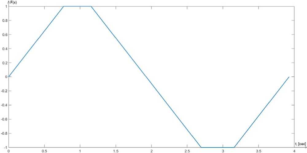
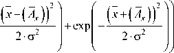
Fig. 6. The shape of the controlling signal in the form of a triangle with saturation zones
Рис. 6. Форма управляющего сигнала в виде треугольника с зонами насыщения
Fig. 7. Beam energy distribution on the surface of a detail when scanning with a truncated raster and changing the boundaries of the saturation zone
Рис. 7. Распределение энергии пучка на поверхности детали при сканировании усеченным растром и при изменении границ зоны насыщения
From the obtained graphs it can be seen that by changing the value of the saturation zone M, it is possible to control the amplitude of the two-hump energy distribution over the heating spot and achieve the best shape of the weld. In order to use the obtained calculated characteristics, it is necessary to get from dimensionless coordinates to dimensional coordinates, for this it is necessary to carry out the following actions [18]:
-
y = y ■□ ; x = x ■□ ; A = A ■□ ;
-
2. The scanning shape in the form of a truncated raster allows to obtain a two-hump distribution of energy along the coordinate across the joint, which is necessary to form a weld with parallel walls and a significant radius in the root, excluding the appearance of root defects.
-
3. Numerical modelling of thermal processes to determine the parameters of EWB will significantly reduce the cost of developing technologies for structures made of new materials and various thicknesses.
W ( x ) W ( y )
W ( x ) = ——; W ( y ) = ——. G G
As a result of the conducted research, a program was developed to control the energy distribution over the heating spot using various scans [19].
Conclusion . 1. For conducting investigations to optimize the process of electron beam welding, it is reasonable to use scanning electron beam in the form of a raster, which allows to obtain a stable penetration cavity and high quality welded joints.
References Features of modeling the electron beam distribution energy for the electron-beam welding process
- Rykalin N. N., Zuev I. V., Uglov A. A. Osnovy elektronno-luchevoy obrabotki materialov [Fundamentals of electron beam processing of materials]. Moscow, Engineering, Publ., 1978, 239 p.
- Sobko S. A., Kulikov V. A. Sposob kontrolya elektronno-luchevoy svarki [The method of control of electron-beam welding]. Available at: http://www.freepatent.ru/patents/2495737 (accessed 13.05.2020).
- Shcherbakov A. B., Rodyakina R. V., Novokreschenov V. V., Lastovirya V. N. Sistemy upravleniya elektronno-luchevykh ustanovok [Technology of material processing. Equipment of electron-beam complexes]. Moscow, Yurayt Publ., 2018, P. 114–130.
- Akopianc K. S., Nesterenko V. M. [Electron-beam welding of steels up to 600 m thick with longitudinal oscillations of the beam]. Avtomaticheskaya svarka. 2002, No. 9, P. 3–5 (In Russ.).
- Ohmine M., Hiramoto S., Jamane J. Fundamental study on the plused electron beam welding // Intern. Inst. of Welding; Doc. IV-348-83 – S. I. 1983, 13 p.
- Belenkiy V. Ya. [Scanning of an electron beam along an x-shaped trajectory as a means of reducing defects in the root of a weld in EBW]. Avtomaticheskaya svarka. 1986, No. 9, P. 35–37. (In Russ.).
- Barishev M. S., Redchic A. A. [Optimization of welding modes by oscillating electron beam]. Tez. dokladov 4-y Vserocs. soyuz. konferentsii po svarke tsvetnykh metallov [Abstracts of the 4th. Rus. Union Conf. on welding of non-ferrous metals]. 1990, 34 p. (In Russ.).
- Zenker R. Electron beam surface treatment and multipool welding – state of the art. Proceedings of the EBEAM 2002. International Conference on High-Power Electron Beam Technology. 2002, P. 12-1–12-5.
- Shilov G. A., Akopianc K. S., Kasatkin O. O. [Influence of the frequency and diameter of the circular scan of the electron beam on the penetration in EBW]. Avtomaticheskaya svarka. 1983, No. 8, P. 25–28 (In Russ.).
- Akopianc K. S., Emchenko-Ribko A. V., Neporohin V. Yu., Shilov G. A. [Prevention of the formation of root defects in EBW with non-penetration of up to 60 mm depth]. Avtomaticheskaya svarka. 1989, No. 4, P. 30–34 (In Russ.).
- Komiro Y., Punshon C. S., Gooch T. G., Blakaley P. S. Effects of process parameters on centerline solidification in EB weld. Metal Constr. 1986, No. 2, P. 104–111.
- Vasil’ev A. M., Goncharov V. A., Krivkov B. G., Solyankin V. V., Sharonov N. I. [Electronic beam control device by welding]. Sudostroitel'naya promyshlennost'. Seriya Svarka. 1988, No. 6, С. 11–12 (In Russ.).
- Mara C. l., Funk E. R., McMaster R. C., Pence P. E. Penetration mechanism of electron beam Welding and spiking phenomenon. Welding Journal. 1974, Vol. 53, No. 6, С. 246–251.
- Béraud N., Vignat F., Villeneuve F., Dendievel R. New trajectories in Electron Beam Melting manufacturing to reduce curling effect. Proceedings of the 47th CIRP Conference on Manufacturing Systems. 2014, P. 738–743.
- Seregin Yu. N., Laptenok V. D., Uspenskiy N. V., Nikitin V. P. [Experimental research on the optimization of the technology of electron-beam welding of aluminum alloys]. Tekhnologii i oborudovanie ELS-2011. 2011. P. 71–80 (In Russ.).
- Seregin Yu. N., Laptenok V. D., Murygin A. V., Bocharov A. N. Experimental research on electron-beam welding technology with a scanning electron beam. 21st Int. Sci. Conf. Resetnev Readings-2017. 2019, Vol. 467, 8 p.
- Venttsel' Ye. S. Teoriya veroyatnostey [Probability theory]. Moscow, Vysshaya shkola Publ., 1999, 576 p.
- Kurashkin S. O., Laptenok V. D., Murygin A. V., Seregin Yu. N. Analytical characteristics of the electron beam distribution density over the heated spot for optimizing the electron-beam welding process. Welding in Russia 2019: State-of-the-Art and Perspectives. 2019, Vol. 681, 7p.
- Kurashkin S. O., Seregin Yu. N., Tynchenko V. S., Petrenko V. E., Myrugin A. V. [The program for the formation of the scanning path of the electron beam in the form of a sine wave in electron beam welding]. Certificate of state registration of a computer program № 2020611327. 2020.
