Flow model in the impeller of a centrifugal pump

Author: Nazarov V.P., Chernenko V.V., Chernenko D.V.
Journal: Siberian Aerospace Journal @vestnik-sibsau-en
Section: Aviation and spacecraft engineering
Article in issue: 3 vol.22, 2021.
Free access
In accordance with the results of the features analysis of foreign design technology and the creation of aerospace technology products, the certification orientation of all types of work can be traced, starting from the preliminary design stage, which imposes particularly high requirements on the quality of calcula-tion methods, algorithms and software used in the design development of the project. Without the advanced level of domestic developments in the field of modeling hydrodynamic processes in aircraft systems, in the next decade it will become impossible to compete with foreign developers of aviation and rocket-space sys-tems. In accordance with modern theoretical and experimental studies, the flow pattern in the flow path of a vane machine is a complex superposition of the main and secondary flows. The article discusses the method for calculating the fluid flow in the interscapular channel of a centrifugal impeller with a finite number of vanes, the construction of the energy characteristics of the impeller and its optimization by the number of vanes. The calculation consists of two parts: firstly, the determination of the theoretical head taking into account the influence of the finite number of vanes based on analysis of force interaction, and, secondly, determination of hydraulic losses in the impeller by integrating friction stresses along the limit-ing surfaces. The results from both parts are used to optimize the number of vanes in the pump impeller. Analytically, an equation for the pressure at a point and the coefficient of influence of a finite number of vanes are obtained. Taking into account the law of friction, an expression was obtained for the pressure loss. The described method for calculating the spatial boundary layer is quite simple and intuitive, and gives approximate results that make it possible to estimate the required quantities. However, there is a need for further elaboration of the method to bring it to a form that makes it possible to calculate the three-dimensional flow of the working fluid in a channel of arbitrary shape. Based on the results of theoretical studies, an algorithm and a calculation program were developed that allow calculating local values. The results of the calculation of the theoretical head in the impeller can be used for a more accurate calcula-tion of a centrifugal pump.
Centrifugal pump, impeller, head, optimization
Short address: https://sciup.org/148329582
IDR: 148329582 | DOI: 10.31772/2712-8970-2021-22-3-494-503
Text of the scientific article Flow model in the impeller of a centrifugal pump
Aircraft traditionally have high requirements in terms of operational and energy characteristics, efficiency and reliability, which is associated with ensuring operational safety and the importance of military, scientific, applied and economic tasks being solved. To improve the performance characteristics of aircraft as a whole, it is necessary to further improve the theory of the processes occurring in the flow path of vane superchargers, which improves the design quality, accelerates the development and commissioning of more modern systems of rocket and space aviation technology.
Further development of aerospace programs stipulates a wide range of applications of centrifugal vane superchargers in the systems for supplying the circulation of the working fluid (correction and docking engine, brake propulsion systems, onboard power sources, thermal control systems for the life of spacecraft etc.).
The problem of theoretical development of the issue of fluid flow in the channels of the flow part of centrifugal vane superchargers is particularly acute. This task presents significant difficulties, since most of these channels have sections variable in area and irregular in shape, as well as a curved median line. Especially difficult in terms of theoretical study is the part of the channels that falls on the impeller. These channels are in rotational motion, and the flow working in them, interacting with the vane, increases its specific energy.
Knowledge of the physical flow pattern in all elements of the flow parts of centrifugal pumping units will allow creating more advanced methods of their calculation and design [1].
At present, centrifugal pumps are one of the elements of pumping equipment, very often used in the designs of modern aircraft engines (aircraft industry). With its help, a preliminary increase in fuel pressure is carried out before entering the fuel system (booster pump), as well as fuel is supplied into the afterburner. The centrifugal pump is controlled by a throttle valve located at the inlet.
Analysis-based design has become widespread in practice, and it is based on a series of verification calculations of the flow in the flow part of the objects under study and the corresponding directional correction of its shape and geometry of the blade rowns.
All new requirements and standards for the efficiency and reliability of pumping equipment are being introduced, and the methods of designing impellar machines developed 20–30 years ago no longer allow achieving the required results [2].
The working process of centrifugal pumps is based on the continuous transfer of energy from the impeller blades to the fluid flow. The flow movement after leaving the impeller has an unsteady turbulent character. The transformation of the flow behind the impeller is carried out by structural elements of the flow path of the pump outlet (annular diffuser, guide vane, volute and conical diffuser), which experience high dynamic loads from pressure pulsations [3].
A variety of types and parameters of pumps requires a reduction in terms and an improvement in the quality of design, which is possible with the use of computer-aided design systems, which are based on mathematical models for calculating flow, losses and predicting pump performance. The use of mathematical models makes it possible to conduct a multivariate design process with an assessment of the qualities of the pump elements and the selection of the optimal option at the design stage.
Currently, quasi-three-dimensional methods have proven themselves to be effective in assessing flow and losses in vane systems of pumps, which require little time to implement in comparison with three-dimensional methods and which give satisfactory results in practice.
Taking into account the need to carry out a large number of calculations, it is difficult to assume that when solving a problem, one can rely only on methods for calculating three-dimensional flows.
A large amount of preliminary work must be performed using two-dimensional approaches, their role in the hierarchical structure of methods used in design is great.
Methods for calculating two-dimensional flow make it possible to take into account the geometric parameters of the flow path and blade rows and, despite the assumptions, have sufficient accuracy and speed for practice.
The currently existing methods for calculating centrifugal pumps are oriented towards relatively high flow rates. This necessitates the creation of an algorithm for finding the design parameters of such a pump [4–7].
Nowadays, a model-oriented approach to development and calculation is an integral technology for designing taking into account tight deadlines and the volume of requirements. The design process must be carried out taking into account integration with the model-oriented design of an aircraft engine [8].
Purpose
To make a method for calculating the fluid flow in the vane channel of a centrifugal impeller with a finite number of vanes, to construct the energy characteristics of the impeller according to the calculations and to optimize it according to the number of vanes.
Method
Analyzing the results of experimental visualization of the flow in the impeller in accordance with
Fig. 1 [1], the difference between the circumferential component of the fluid velocity and the peripheral velocity of the driving disk at the free-flow side of the vane can be concluded as well as their equality on the pressure side.
Taking into account the fact that the force interaction in a fluid propagates only in the form of a longitudinal elastic wave, it can be concluded that the instantaneous direction of the fluid velocity should coincide with the rectilinear direction of wave propagation (force interaction). If we neglect the dissipation of the energy motion and assume that the damping of the wave on the scale of the considered geometric forms does not occur, it can be assumed that the value of the instantaneous velocity along the line of elastic force interaction is the value constant.
The initial (generating) point of the line of elastic force interaction is located on the surface of the vasne and sets the value of the velocity along the line, therefore, it is possible to set a family of characteristic lines for the translational motion, along which the value of the translational velocity is determined and constant.
Based on the foregoing, it is possible to write down an expression for the head at each point at the outlet of the impeller for various types of vanes.
The design model for an impeller with rectilinear tangential vanes is shown in Fig. 2.
In this case, the expression for the pressure will take the form
Hj =C2uj⋅U2=Uпер⋅cosγ⋅U2=Ui⋅cosγ⋅U2.(1)
Since the peripheral velocity is determined by the expression
U=R⋅ω ⇒ Hj=Ri⋅R2⋅ω2⋅cosγ.(2)
The radius at any point of the vane is determined by the expression
Ri = R2 ⋅ cosγ.(3)
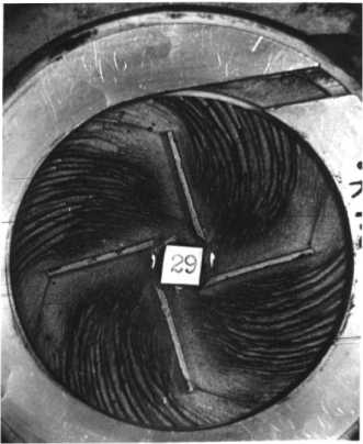
Fig. 1. Visualization of the flow in the impeller of a low-flow pump with rectilinear vanes:
V = 50 · 10–6 m3/s; D 2 = 0,0405;
b 2 = 0,003; D 1 = 0,0155
Рис. 1. Визуализация течения в рабочем колесе МН с прямолинейными лопатками:
V = 50 · 10–6 м3/с; D 2 = 0,0405;
b 2 = 0,003; D 1 = 0,0155
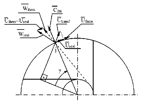
Fig. 2. Design model for an impeller with rectilinear tangential vanes
Рис. 2. Расчетная схема для колеса с прямыми тангенциальными лопатками
Finally, the expression for the pressure at point j will be written in the form
Hj = R 2 2 ⋅ω 2 ⋅ cos2 γ . (4)
The theoretical head with a finite number of vanes is determined step by step according to the following algorithm. At a step, the increment of the angle γ is specified. The pressure value at the current point is determined by the formula (4). The theoretical head is defined as the averaging of the obtained values n ∑Hj
H = j =1 n
.
Influence coefficient of a finite number of vanes kZ =
HT
и,
T ∞
The value of the theoretical head with an infinite number of vanes is determined by the classical expression of the jet theory of Euler [9].
Figure 3 shows the change in the theoretical head with a finite number of vanes depending on the number of vanes.
Given the complexity of viscous flows in the impeller grids, the actual characteristics differ from the theoretical ones by the amount of hydraulic losses
H = H - ∆H = η H .
Hydraulic losses depend on the magnitude and direction of relative velocities in the flow part of the grid and are determined by the integral of friction stresses on the cooling surfaces: the cylindrical surfaces of the vanes and the end surfaces of the covering discs.
At present, the estimation of the actual head values depending on the basic geometric and operating parameters of the grid in most practical applications is based on semi-empirical expressions obtained on the basis of generalization and analysis of experimental data [10–13].
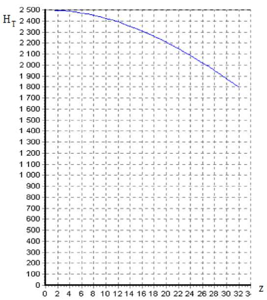
Fig. 3. Theoretical head at a finite number of vanes
Рис. 3. Теоретический напор при конечном числе лопаток
A method for determining hydraulic losses, which is the integration of friction stresses along the limiting surface of a curved channel, is presented in work [1]. Here, when integrating the finite-difference analogs of the equations of momentum of the spatial boundary layer at each step, the thickness of the momentum loss 8Ф ** and the slope angle of the bottom streamline e are calculated.
The total head drop is written as an integral [14]
AH = AP = P2 P = 1 ds = 1 t0dфd^ .(8)
P P PS 0
Expanding t o into projections, we obtain
T0 = у/Т0ф + T0V ;
AH = 1f 7Т0ф + T2V ■dфdV .
P S ’
Considering, that t 0 v = ет 0 ф , we get
A H =
1 J ^тО ф + е 2 т 0ф d Ф d V= 1 ^( 1 + s 2 )J^ d ф d v .
From the law of friction [15]
-0,25
I T TO** \ ’
Т 0ф
= 0,01256 p U2
V
Substituting in (11) we obtain the expression for the head loss
AH =
1-JF2) J
P S
Т о ф d ф d v = 0,01256 •
^2) } J U 2 • S
**
U 5 ф
V
\ -0,25
d ф d\\i.
Substituting the found values e and 8 ф ** , we get the value of the head loss.
The presented method for calculating the spatial boundary layer is quite simple and intuitive. However, there is a need for further development of the method to bring it to a form that allows calculating the three-dimensional flow of the working fluid in a channel of arbitrary shape.
It should be noted that the results of comparing the numerical and experimental visualization show a similar flow pattern, which indirectly confirms the validity of assumptions and the correctness of conclusions when constructing a method for determining the transfer velocity field in the interscapular channel of the impeller.
Based on the results of theoretical studies, an algorithm and a calculation program were developed that allow calculating local values Н along the length of the interscapular channel step, known geometric parameters of the impeller, angular velocity and flow rate. The calculation of the theoretical head in the impeller with straight vanes is carried out.
Sample calculation results are shown in Fig. 4, 5. Fig. 4 shows the hydraulic head losses along the length of the channel.
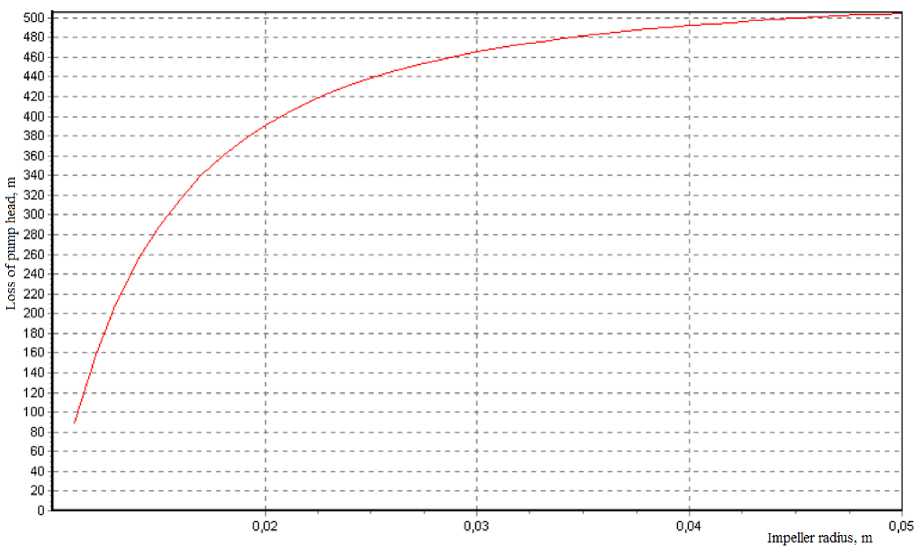
Fig. 4. Hydraulic head losses along the channel length
Рис. 4. Гидравлические потери напора по длине канала
Fig. 5 shows the dependence of the influence coefficient of the finite number of vanes kz , of hydraulic efficiency n r and the optimization parameter kz • nr on the number of vanes in the impeller.
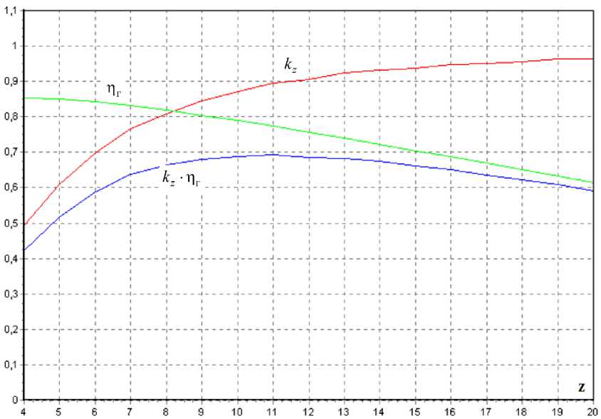
Fig. 5. Dependences of k , η and ( k ⋅η )on the number of vanes
Рис. 5. Зависимость k , η и ( k ⋅η ) от числа лопаток
After performing a series of calculations for a different number of vanes, it is possible to choose the most optimal option according to the criterion k ⋅ η → max.
Conclusion. The article presents a method for calculating the fluid flow in the interscapular channel of a centrifugal impeller with a finite number of vanes, the construction of the energy characteristics of the impeller and its optimization by the number of blades. The proposed method was used to calculate the flow, which consists of two parts:
-
1) the theoretical head is determined taking into account the influence of a finite number of vanes based on the analysis of force interaction;
-
2) hydraulic losses in the impeller are determined by integrating friction stresses along the limiting surfaces. The materials presented in this article allow using the results of both parts to optimize the number of vanes in the pump impeller.
References Flow model in the impeller of a centrifugal pump
- Chernenko D. V. Gidrodinamika tsentrobezhnykh lopatochnykh nagnetateley energosilovykh ustanovok letatel'nykh apparatov. Kand. Diss. [Hydrodynamics of centrifugal vane superchargers of power plants of aircrafts. Cand. Diss.]. Krasnoyarsk, SibSAU, 2005, 167 p.
- Lomakin V. O. Razrabotka metoda optimal'nogo proektirovaniya otvodyashchego ustrojstva neftyanogo magistral'nogo nasosa. Dokt. Diss. [Development of a method for the optimal design of a diverting device for an oil main pump. Doct. Diss.]. Moscow, Bauman Moscow State Technical University, 2017, 250 p.
- Korchinskij V. V. Razrabotka trubchatyh napravlyayushchih apparatov v otvodah vysokoobo-rotnyh centrobezhnyh nasosov s cel'yu snizheniya vibroaktivnosti i uvelicheniya resursa raboty. Kand. Diss. [Development of tubular guide vanes in the outlets of high-speed centrifugal pumps in order to reduce vibration activity and increase the service life. Cand. Diss.]. Moscow, Moscow Aviation Insti-tute (National Research University), 2017. 119 p.
- Bojko L. G., Barysheva E. S., Demin A. E., Drynov O. N. [Computational study of the flow in an axial centrifugal compressor of an aviation GTE]. Vestnik UGATU. 2013, Vol. 17, No. 4 (57), P. 29–37 (In Russ.).
- Pugachev P. V. Razvitie metodov rascheta elementov protochnoj chasti shneko-centrobezhnyh nasosov na osnove dvuhmernyh i trekhmernyh modeley techeniya. Kand. Diss. [Development of meth-ods for calculating the elements of the flow path of screw-centrifugal pumps based on two-dimensional and three-dimensional flow models. Cand. Diss.]. St. Petersburg, 2012, 161 p.
- Karabanova V. V., Vanyashov A. D., Yusha V. L. [Some features of the implementation of the design model of a high-pressure centrifugal compressor stage with outlet guide vanes]. Omskiy nauch-nyy vestnik. 2019, Vol. 3, No. 2, P. 62–70 (In Russ.).
- Protopopov A. A. [Calculation of the optimal parameters of a semi-open impeller of a low-flow centrifugal pump]. Izvestiya MGTU MAMI. 2015, Vol. 1, No. 4, P. 82–89 (In Russ.).
- Bilalov R. A., Sulimova D. A. Sovremennye sposoby proektirovaniya SAU aviacionnyh dvigate-lej na osnove model'no-orientirovannogo podhoda [Modern methods of designing ACS of aircraft en-gines based on a model-based approach]. Moscow, ICAM 2020, 468 p.
- Kirillov I. I. Teoriya turbomashin [Turbomachine theory]. Leningrad, Mashinostroyeniye Publ., 1972, 536 p.
- Stodola A. Steam and gas turbines. New York, P. Smith, 1945, 736 p.
- Eckert B. Osevye i tsentrobezhnye kompressory [Axial and centrifugal compressors]. Moscow, Mashgiz Publ., 1959, 680 p.
- Proskura G. F. Gidrodinamika turbomashin [Hydrodynamics of turbomachines]. Moscow, Mashgiz Publ., 1954, 417 p.
- Pfleiderer K. L. Lopatochnye mashiny dlya zhidkostey i gazov [Vane machines for liquids and gases]. Moscow, Gostechizdat Publ., 1960, 684 p.
- Schlichting G. Teoriya pogranichnogo sloya [Boundary layer theory]. Moscow, Nauka Publ., 1969, 744 p.
- Stepanov G. Yu. Gidrodinamika reshetok turbomashin [Hydrodynamics of turbomachine grids]. Moscow, Phismatgiz Publ., 1962, 512 p.
