Focusing of light beams with the phase apodization of the optical system

Author: Reddy Andra Naresh Kumar, Martinez-Corral Manuel, Khonina Svetlana Nikolaevna, Karpeev Sergei Vladimirovich
Journal: Компьютерная оптика @computer-optics
Section: Дифракционная оптика, оптические технологии
Article in issue: 4 т.42, 2018.
Free access
We investigated reduction of the size of the illuminated beam in the focal region produced by the optical systems of NA=0.99 has been. The intensity distributions of polarized light field in the focal volume for the phase apodization pupil have been discussed. The circular pupil in different phase apodization situations can be employed to control the field components in the resultant in-tensity distribution. We show that both axial and transverse resolution improvement in the focal distribution is possible by applying proper phase engineering in the annulus of the pupil function.
Focal spot, phase apodization, linear polarization, resolution, high numerical aperture focusing system
Short address: https://sciup.org/140238484
IDR: 140238484 | DOI: 10.18287/2412-6179-2018-42-4-620-626
Text of the scientific article Focusing of light beams with the phase apodization of the optical system
The optical focusing systems claim the great importance since the origin of the laser. These systems are widely used in the industrial, medical, military and the nuclear research applications. The size and shape of the focal spot of the optical system depend on the polarization of the incident radiation and the field distribution across the exit pupil function. There are certain techniques and tools introduced for narrowing the focused light beams with respect to the incident light polarization [1–3]. The importance of these techniques depends upon the manufacturing and the cost tolerances. In the present work, we introduced the simple and easy phase engineering pupil structures applied for the apodization and enhanced resolution focal spots of the beam-propagation and – focusing systems illuminated by linearly polarized light beams. Recent past, there are several studies drawn attention to the technical possibilities for improving the resolution of the focal spot axially and laterally. In similar context, the amplitude distribution in the focal region has been reconstructed by the introducing the stop at the center of the pupil function [4–5], However,by employing the simple phase elements in the pupil plane, the sidelobes in the spatial distribution have been suppressed to negligible level, results, the sharp focal spot [6–8]. In another proposed approach, the size of the focal spot laterally of radially polarized incident light was investigated [9–11]. Later, more effectively, a narrow focal spot produced by a high numerical aperture focusing systems with simple phase diffractive structures for differently polarized incident laser beams [12]. Particularly, the proposed pupil filters can be in the form of diffractive elements have been applied to produce the microscopy based polarized beams [12–13] and non-homogeneously polarized light beams [14–17]. In the above studies few dif- fractive structures more complex to design and some require expensive optical environment to implement. For sake of easy demonstration we initially simulated the point spread function based on the scalar-wave diffraction [18–20], can be used to characterize the focal spot for phase engineering scheme. In general, a fine focusing of light with a suitable optical element is important for many practical applications. However, in this paper, we design an efficient pupil function which can be utilized for focusing of widely used linearly polarized laser beams. In other word, focusing the electromagnetic radiation with the phase engineered circular diffractive structures of high numerical aperture has considered in this work follow the focusing systems which were investigated in the recent papers [6, 12, 23–25]. The proposed apodization pupil is practically possible to design and easy to implement which can be useful to achieve enhanced resolution and to manipulate the sidelobes level in the vicinity of focus. Note that, current approach facilitates to approximate the incident wavefront scattered by phase apodization pupil and the sum of these components determines the structure of the focal region.
Scalar representation of the field distribution in the focal area
For two dimensional image forming system, the incident plane wave propagating in a direction perpendicular to the diffracting screen and results, the spatial distribution of light in the focal region of the optical system has been computed from Eq.(1). Here we considered a circular entrance pupil of specified radius, a ring is isolated from the circular entrance, which has divided into the two equal halves having phase opposition in their transmit-tances. Note, that by putting the asymmetric aperture in the pupil plane of the optical focusing system, one can eliminate the lower order optical side-lobes of the incident field distribution. This is an important result which is helpful to solve a practical problem known as two-point resolution [27–28], i.e. two closely spaced objects which are to be viewed in the presence of geometrical aberrations [21–22], Rays emanating from the points will form the point spread function (PSF) patterns around their paraxial image points.
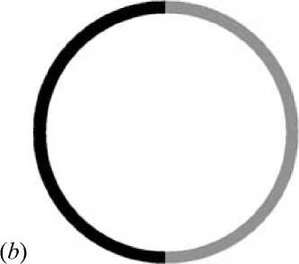
The total transmittance distribution of the circular pupil is given in the Fig. 1 b . It has the function form g ( r , p ), represented by the Eq. (3). On the image plane, the total diffraction field amplitude G ( x , y ) contributing by the pupil function is equal to the sum of the diffraction components contributing by the circular entrance, the left and right half ring is given by Eq.(1), which is written as Eq. (2) in polar coordinates:
Vector representation of the field distribution in the focal area
The vector electric field in a homogeneous dielectric medium close to the focus can be described by Debye approximation [6, 12, 23–25, 29]:
E ( x , y , z ) =
' Ex ( x , y , z )' E y ( x , y , z )
v E z ( x , y , z ) v
if
X
J j B ( в , ф ) P ( 0 , Ф )
x
r
ik r r ik
G ( x , У )=-7-7 Jf g(u , v )exp ——( xu + yv ) d u d v , (1)
2nf
-r
r 2П
G(P, 9)=—7 [ J g(r, Ф)x 2nf 00
ik x , x exp--rpcos(O-p) r dr dф,
|o.
g ( r , ф) =
1,
R
>
r
>
R
-A
, /2
<
ф
<
3n/2, 0
<
r
The parameters we considered in the above expressions are determined as, follows: wavelength of mono-
chromatic plane wave X = 0.000532 mm, radius of the apodization pupil function R = 10 mm, at the periphery of the circular entrance, the width of the half ring A = 1 mm and the focal length of the lens f =300 mm. The calculations (Figs. 1, 2) were performed by using the Fourier transforms (1), (2).

Fig. 1. Pupil apodization function: amplitude (a) and phase (b)
The PSF intensity distribution shown in the fig. 2 c is the spatial redistribution of the field with the suppressed side-lobes (right) and the enhanced side-lobes (left), i.e., the apodized PSF, in which a side-lobes are suppressed to the zero-level intensity and the principal maximum is found to be narrow on one side of the diffraction pattern. Here the right side of the PSF is obtained at the cost of worsening its counterpart. The resolution of the optical system is improving by a simultaneous suppression of the side-lobes and narrowing the principal maximum in a half part of the resultant pattern in the focal region.
x exp [ ik ( x sin в cos ф + y sin в sin ф + z cos в ) ] x
x Vcos в sin в d 9 d ф ,
where ( x, y, z ) are Cartesian coordinates of the focal area, ( в , ф ) are the spherical angular coordinates of the output pupil of the focusing system, B ( в , ф ) is the transmission function (analogue to the apodization function from Eq. (3), P ( в , ф ) is the polarization vector, n sin в max =NA, n is the refractive index of the media, k =2 п / X is the wave number, X is the wavelength, f is the focal length. The calculations were performed with the aid of the integral (4) for linear x- polarization when the polarization vector is expressed by:
P x - lin ( в , ф ) =
Л 1 + cos 2 ф (cos в- 1) Л sin ф cos ф (cos в- 1)
- sin в cos ф
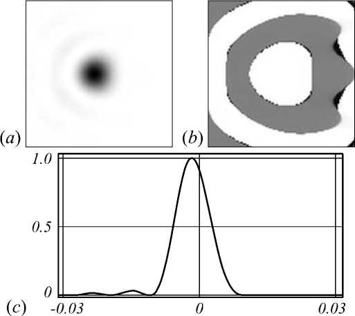
Fig. 2. The field in the Fourier plane is: the intensity (negative) (a), the phase (b), the vertical graph of the intensity (c)
The intensity of the field in the focal plane ( z =0) was calculated as the sum of component intensities:
I E x ( x , y , z )|2 + E y ( x , y , z )|2 + E z ( x , y , z )|2 . (6)
Table 1 shows the axial distributions of linear x -pola-rized electric field intensity in the focal region, produced under different considerations in the pupil plane. It is equal to the sum of different electric field components from various zones of the pupil function. Here we considered an aplanatic pupil system (free from spherical aberration) with high numerical aperture (NA=0.99) gives the resultant field distribution in the focal region as shown in the Table 1.
The lateral distribution area has shown in the focal plane ( z = 0) is restricted by a 4 Xx 4 X size, X = 1mm. Here
we can observe the tight focusing of laser beams with phase apodization pupils and localization of light in the focal region is investigated with linear x-polarization type. In the given considerations, we obtained the full width at half maximum (FWHM) along the x- and y- directions which are defined in the Tables 1 and 2 as Sx and Sy.
Table 1. Results of the phase apodization for linear x-polarization at full aperture, NA = 0.99
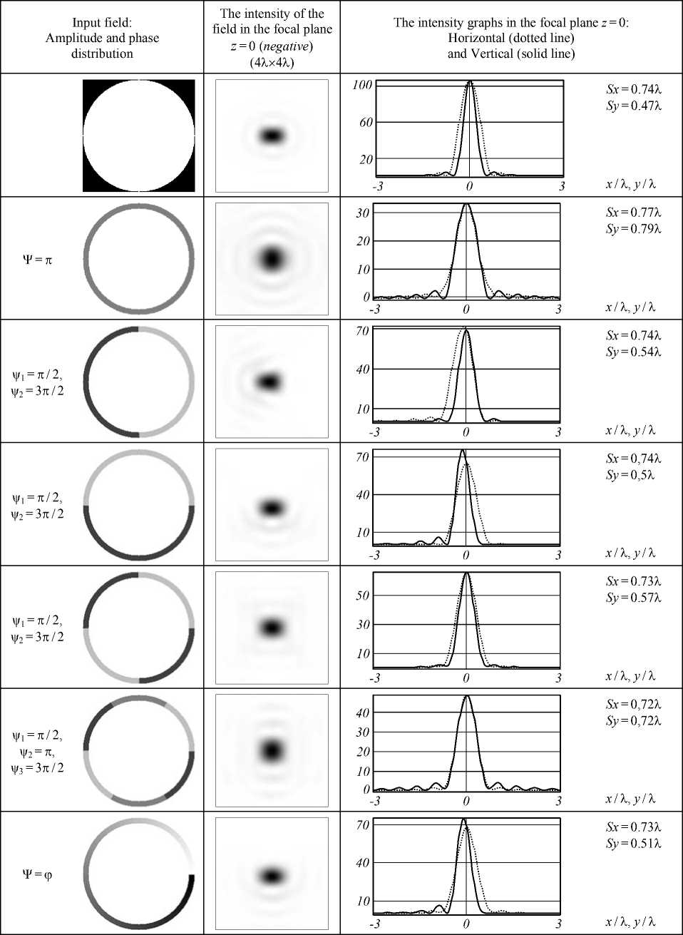
Table 2. Results of the phase apodization for linear x-polarization at narrow ring aperture, NA = 0.99
|
Input field: |
The intensity of the field |
The intensity graphs in the focal plane z =0: |
|||||
|
Amplitude and phase |
in the focal plane z =0 |
Horizontal (dotted line) |
|||||
|
distribution |
( negative ) (4 λ× 4 λ ) |
and Vertical (solid line) |
|||||
|
5 |
Sx = 0.84 λ |
||||||
|
ИН |
f |
||||||
|
Sy =0.33 λ |
|||||||
|
3 |
|||||||
|
И |
|||||||
|
1 |
|||||||
|
госхУХ/Х) |
адххх^ |
||||||
|
3 |
0 |
x / λ , y / λ |
|||||
|
4 |
Sx = 1.4 λ |
||||||
|
3 |
Sy = 0.52 λ |
||||||
|
ψ 1 = π /2, । |
2 |
||||||
|
ψ 2 =3 π /2 |
1 |
||||||
|
3 |
0 |
x / λ , y / λ |
|||||
|
Sx = 0.62 λ |
|||||||
|
Sy = 0.32 λ |
|||||||
|
ψ1 = π /2, |
|||||||
|
ψ2 =3 π /2 |
1 |
||||||
|
\AAaZ\v |
|||||||
|
3 |
0 |
x / λ , y / λ |
|||||
|
2 |
Sx = 0.38 λ |
||||||
|
ψ 1 = π /2, |
|||||||
|
1 |
Sy = 0.49 λ |
||||||
|
ψ 2 =3 π /2 |
|||||||
|
3 |
0 |
x / λ , y / λ |
|||||
|
2 |
л |
Sx =0.9 λ |
|||||
|
ψ 1 = π /2, ψ 2 = π , |
Sy = 0.41 λ |
||||||
|
1 |
|||||||
|
wv^ |
|||||||
|
ψ3=3 π /2 |
|||||||
|
3 |
0 |
x / λ , y / λ |
|||||
|
3 |
Sx = 0.47 λ |
||||||
|
ф |
Sy = 0.87 λ |
||||||
|
2 |
|||||||
|
ψ = ϕ |
|||||||
|
хухУХМ |
V |
||||||
|
3 |
0 |
x / λ , y / λ |
|||||
For the unapodized pupil of NA=0.99 (1st row of Table 1) results the elongated focal spot, one can obtain the horizontal, vertical components in the axial distribution of the electric field with FWHMx of 0.74λ and FWHMy of 0.47λ. The apodization pupils with phase change (ψ) of π in the annulus (2nd row of Table 1) of the pupil allow an optical system for achieving the circular focal spot with FWHMx of 0.74λ and FWHMy of 0.79λ. As the ring separated from the circular entrance of the pupil is divided into equal halves among which the left half ring with phase (ψ1) of π /2 and the right half ring with phase (ψ2) of 3π /2 (3rd row of Table 1) produces the asymmet- ric focal spot i.e., the resultant electric field intensity distribution in the focal volume has found with suppressed side-lobes. In this case the right side pattern (low sidelobes side) is obtained at the cost of the left side pattern. The vertical size of the linear x-polarized component of the electric field has modified by the apodization pupil, and the redistributed focal volume with FWHMx of 0.54λ whereas the horizontal component FWHMy of 0.74λ shifts towards the left side of the focus.
In another approach, the annulus of the pupil function is configured with similar phase engineering, but the angle of orientation for the annulus changes (as seen in 4th row of Table 1), results the vertical and horizontal components of the focal spot are altered. The size of focal spot is reduced in the vertical direction with the FWHM of 0.5λ which is much lower than that of the unapodized case. In this case the suppression of the sidelobes in the focal distribution has been improved on one side of the focal volume. While phase engineering in the annulus is necessary for light focusing, shifting and resolution gain, therefore, the vertical component of the resultant field distribution shifts towards the left side of the pattern comes as a result of simultaneous suppression of sidelobes and sharpened focus on the right side of the component is obtained at the cost of the field distribution on the counter side of the component. In another case, it can be seen that with a phase switching of ψ1 and ψ2 in the annulus with the angle of orientation (θ) 90o around the circular entrance restricts the input field and present the focal volume with the optimized field distribution (As see in 5th row of Table 1), thus the sidelobe levels are reduced in the contributions of the vertical and horizontal components of the focal distribution. In this case we have shown that light focusing with subwavelength diffraction localization is significantly modified and the focal spot size in vertical and horizontal directions is computed as 0.73λ and 0.57λ, respectively.
It is observed that with the annulus ring, it is possible to generate various combinations of phases ψ 1 , ψ 2 and ψ 3 spanning the entire 360° range produces the rectangular focal spot (6th row of Table 1). In this case, the horizontal component in the resultant field distribution contributes the sidelobes with the zero-level intensity and obtained the FWHM of 0.72λ which is as same as the size of the field component in vertical direction. For a continuous phase change annulus ring around the circular entrance pupil (as seen in 7th row of Table 1), the intensity of the sidelobes in the right half of the field components in vertical and horizontal directions is controlled to the zerointensity level and the zero-order spot found to be sharp on the same side of the vertical and horizontal components, results the focal spot with FWHMx=0.73λ and FWHMy=0.51λ.
While the ring aperture with no apodization (as shown in 1st row of Table 2) produces the focal volume in which the full width at half maximum (FWHM) of the focal spot in vertical direction is computed as 0.33λ whereas the FWHM of the horizontal component is 0.84λ. Therefore, the resolution of the focal spot in the vertical direction is found beyond the diffraction limit. By controlling the phase of the annulus around the circular entrance in the form of ψ1 and ψ2, the horizontal component of the electric field intensity lost its shape in the focal volume [6, 12], however, it is efficient to control the subwavelength structure in vertical direction (as displayed in 2nd row of Table 2). In this consideration, for the phase engineered annulus, the FWHM of the vertical component of the field is computed as 0.52λ. While, with similar phase configuration annulus of 90° orientation angle the input field is restricted and demonstrating generation of double elongated focal spots (3rd row of Table 2), re- sults the size of the focal spots in vertical direction is altered to 0.32λ, which is less than that of the diffraction limit while the size of the focal spots in horizontal direction is 0.62λ. Compact closely spaced light spots are of practical interest in the problems of interaction of femtosecond laser radiation with matter [30,31], imaging of the far-field objects separated in a close distance [28] and it can be applied to compensate the defocusing effect [32–33] at the telescope objective results superresolution astronomical imaging for point sources. Here the apodization efficiency is defined to provide better sidelobe control and resolution gain.
As the phase in the annulus switches from ψ 1 to ψ 2 and vice versa around the pupil entrance produces a complex focal field, in which the size of the focus in the horizontal and vertical directions is computed as 0.38λ and 0.49λ, as illustrated in 4th row of Table 2. However, the subwavelength light distribution corresponding to higher order in the horizontal component of the field is restricted by the phase apodization pupil. On other hand, a focal volume produced by the annulus ring with the phase variation of ψ 1 , ψ 2 and ψ 3 (as shown in 5th row of Table 2) demonstrated that the size of the focus for horizontal component is measured as 0.9λ, results the central interior energy in the focus dispersed into the corresponding orders is responsible to redistribute the subwavelength diffraction in the total field intensity. In application of continuous coded phase (ψ) spanning the entire 360° range over the circular entrance (as shown in the 6th row of Table 2), the field distributions near the focus is almost as same as the field distributions around the focus produced by the ring structure shown in the 1st row of Table 2. Since the size of the focal spot produced by the phase apodization pupil for horizontal and vertical components is 0.47λ and 0.87λ, respectively.
Conclusion
Among the discussion, it is concluded that the spatial redistributions produced by the full aperture of NA=0.99 under various phase apodization conditions results the focal spot with decrease in size. It has shown that the sidelobes are suppressed in the contributions of the vertical and horizontal components of the focal volume. This fact should be considered when a laser beam with linear polarization illuminates the lens pupil, results the smoothened distribution obtained on one side of the field components at the cost of the distribution on the counter side of the field components. This spatial redistribution is useful to the characterize the resolution of two closely associated point sources. By employing the ring aperture (NA=0.99), one can obtain a focal spot with size beyond the diffraction limit. The phase apodization pupil that we proposed leads to design efficient focusing systems and also applied to improve the performance of the high numerical aperture imaging systems.
References Focusing of light beams with the phase apodization of the optical system
- Dorn, R. A sharper for radially polarized light beam/R. Dorn, S. Quabis, G. Leuchs//Physical Review Letters. -2003. -Vol. 91. -233901. - DOI: 10.1103/PhysRevLett.91.233901
- Sheppard, C.J.R. Annular pupils, radial polarization, and superresolution/C.J.R. Sheppard, A. Choudhury//Applied Optics. -2004. -Vol. 43, Issue 22. -P. 4322-4327. - DOI: 10.1364/AO.43.004322
- Wang, H. Creation of a needle of longitudinally polarized light in vacuum using binary optics/H. Wang, L. Shi, B. Lukyanchuk, C. Sheppard, T.C. Chong//Nature Photonics. -2008. -Vol. 2. -P. 501-505. - DOI: 10.1038/nphoton.2008.127
- Quabis, S. Focusing light to tighter spot/S. Quabis, R. Dorn, M. Eberler, O. Glöckl, G. Leuchs//Optics Comunications. -2000. -Vol. 179, Issues 1-6. -P. 1-7. - DOI: 10.1016/S0030-4018(99)00729-4
- Davidson, N. High-numerical-aperture focusing of radially polarized doughnuts beams with a parabolic mirror and a flat diffractive lens/N. Davidson, N. Bokor//Optics Letters. -2004. -Vol. 29, Issue 12. -P. 1318-1320. - DOI: 10.1364/OL.29.001318
- Khonina, S.N. Controlling the contribution of the electric field components to the focus of a high numerical aperture lens using binary phase structures/S.N. Khonina, S.G. Volotovsky//Journal of the Optical Society of America A. -2010. -Vol. 27, Issue 10. -P. 2188-2197. - DOI: 10.1364/JOSAA.27.002188
- Sun, C.C. Ultrasmall focusing spot with a long depth of focus based on polarization and phase modulation/C.C. Sun, C.K. Liu//Optics Letters. -2003. -Vol. 28, Issue 2. -P. 99-101. - DOI: 10.1364/OL.28.000099
- Huang, K. Design of DOE for generating a needle of a strong longitudinally polarized field/K. Huang, P. Shi, X.-L. Kang, X. Zhang, Y.-P. Li//Optics Letters. -2010. -Vol. 35, Issue 7. -P. 965-967. - DOI: 10.1364/OL.35.000965
- Zhou, Z. Achromatic generation of radially polarized beams in visible range using segmented subwavelength metal wire gratings/Z. Zhou, Q. Tan, Q. Li, G. Jin//Optics Letters. -2009. -Vol. 34, Issue 21. -P. 3361-3363. - DOI: 10.1364/OL.34.003361
- Volpe, G. Generation of cylindrical vector beams with few-mode fibers excited by Laguerre-Gaussian beam/G. Volpe, D. Petrov//Optics Communications. -2004. -Vol. 237, Issues 1-3. -P. 89-95. - DOI: 10.1016/j.optcom.2004.03.080
- Kozawa, Y. Generation of a radially polarized beam by use of a conical Brewster prism/Y. Kozawa, S. Sato//Optics Letters. -2005. -Vol. 30, Issue 22. -P. 3063-3065. - DOI: 10.1364/OL.30.003063
- Khonina, S.N. Simple phase optical elements for narrowing of a focal spot in high-numerical-aperture conditions/S.N. Khonina//Optical Engineering. -2013. -Vol. 52, Issue 9. -091711. - DOI: 10.1117/1.OE.52.9.091711
- Igelesias, I. Polarization is structuring for focal volume shaping in high-resolution microscopy/I. Igelesias, B. Vohnsen//Optics Communications. -2007. -Vol. 271, Issue 1. -P. 40-47. - DOI: 10.1016/j.optcom.2006.10.001
- Khonina, S.N. Polarization converter for higher-order laser beams using single binary diffractive optical element as beam splitter/S.N. Khonina, S.V. Karpeev, S.V. Alferov//Optics Letters. -2012. -Vol. 37, Issue 12. -P. 2385-2387. - DOI: 10.1364/OL.37.002385
- Neil, M.A.A. Method for the generation of arbitrary complex vector wave fronts/M.A.A. Neil, F. Massoumian, R. Juškaitis, T. Wilson//Optics Letters. -2002. -Vol. 27, Issue 21. -P. 1929-1931. - DOI: 10.1364/OL.27.001929
- Khonina, S.N. Grating-based optical scheme for the universal generation of inhomogeneously polarized beams/S.N. Khonina, S.V. Karpeev//Applied Optics. -2010. -Vol. 49, Issue 10. -P. 1734-1738. - DOI: 10.1364/AO.49.001734
- Davis, J.A. Two-dimensional polarization encoding with a phase only liquid-crystal spatial light modulator/J.A. Davis, D.E. McNamara, D.M. Cottrell, T. Sonehara//Applied Optics. -2000. -Vol. 39, Issue 10. -P. 1549-1554. - DOI: 10.1364/AO.39.001549
- Jacquinot, P. Apodization/P. Jacquinot, B. Roizen-Dossier//Progress in Optics. -1964. -Vol. 3. -P. 29-32.
- Barakat, R. Solution to the Lunenberg apodization problems/R. Barakat//Journal of the Optical Society of America. -1962. -Vol. 52. -P. 264-272.
- Ratnam, C. Comparison of PSF maxima and minima of multiple annuli coded aperture (MACA) and complementary multiple annuli coded aperture (CMACA) systems/C. Ratnam, V. Lakshman Rao, S.L. Goud//Journal of Physics D: Applied Physics. -2006. -Vol. 39. -P. 4148-4152. - DOI: 10.1088/0022-3727/39/19/005
- Sayanna, R. Effects of defocusing on the sparrow limits for apodized optical systems/R. Sayanna, D. Karuna Sagar, S.L. Goud//Optics Communications. -2003. -Vol. 217, Issues 1-6. -P. 59-67. - DOI: 10.1016/S0030-4018(02)02291-5
- Karuna Sagar, D. Defect of focus in two-line resolution with Hanning amplitude filters/D. Karuna Sagar, G. Bikshamaiah, M.K. Goud, S.L. Goud//Journal of Modern Optics. -2006. -Vol. 53, Issue 14. -P. 2011-2019. - DOI: 10.1080/09500340600787507
- Rao, L. Focus shaping of cylindrically polarized vortex beams by a high numerical aperture lens/L. Rao, J. Pu, Z. Chen, P. Yei//Optics and Laser Technology. -2009. -Vol. 41, Issue 3. -P. 241-246. - DOI: 10.1016/j.optlastec.2008.06.012
- Chen, B. Tight focusing of the elliptically polarized vortex beam/B. Chen, J. Pu//Applied Optics. -2009. -Vol. 48, Issue 7. -P. 1288-1294. - DOI: 10.1364/AO.48.001288
- Khonina, S.N. Vortex phase transmission function as a factor to reduce the focal spot of the high aperture system/S.N. Khonina, N.L. Kazanskiy, S.G. Volotovsky//Journal of Modern Optics. -2011. -Vol. 58, Issue 9. -P. 748-760. - DOI: 10.1080/09500340.2011.568710
- Cheng, L. Asymmetric apodization/L. Cheng, G.G. Siu//Measurement Science and Technology. -1991. -Vol. 2. -P. 198-202. - DOI: 10.1088/0957-0233/2/3/002
- Reddy, A.N.K. Two-point resolution of asymmetrically apodized optical systems/A.N.K. Reddy, D. Karuna Sagar//Óptica Pura y Aplicada. -2013. -Vol. 46, Issue 3. -P. 215-222. - DOI: 10.7149/OPA.46.3.215
- Reddy, A.N.K. Far-field light imaging in the presence of atmospheric turbulence with rotating anti-phase apertures: Theoretical investigation/A.N.K. Reddy, P. Verma, S.N. Khonina, M. Hashemi, M. Martinez-Corral//2017 IEEE International Conference on Industrial Technology (ICIT). -2017. -P. 1008-1012. - DOI: 10.1109/ICIT.2017.7915499
- Richards, B. Electromagnetic diffraction in optical systems, II. The structure of the image field in an aplanatic system/B. Richards, E. Wolf//Proceedings of the Royal Society A. -1959. -Vol. 253. -P. 358-379. - DOI: 10.1098/rspa.1959.0200
- Uryupina, D.S. Femtosecond laser-plasma interaction with prepulse-generated liquid metal microjets/D.S. Uryupina, K.A. Ivanov, A.V. Brantov, A.B. Savel'ev, V.Yu. Bychenkov, M.E. Povarnitsyn, R.V. Volkov, V.T. Tikhonchuk//Physics of Plasmas. -2012. -Vol. 19, Issue 1. -013104. - DOI: 10.1063/1.3675871
- Khonina, S.N. Study by focusing into closely spaced spots via illuminating a diffractive optical element by a short-pulse laser beam/S.N. Khonina, S.A. Degtyarev, A.P. Porfirev, O.Yu. Moiseev, S.D. Poletaev, A.S. Larkin, A.B. Savelyev-Trofimov//Computer Optics. -2015. -Vol. 39, Issue 2. -P. 187-196. - DOI: 10.18287/0134-2452-2015-39-2-187-196
- Reddy, A.N.K. Complex pupil mask for aberrated imaging of closely spaced objects/A.N.K. Reddy, D. Karuna Sagar, S.N. Khonina//Optics and Spectroscopy. -2017. -Vol. 123, Issue 6. -P. 940-949. - DOI: 10.1134/S0030400X17120189
- McKechnie, T.S. The effect of defocus on the resolution of two points/T.S. McKechnie//Journal of Modern Optics. -1973. -Vol. 20, Issue 4. -P. 253-262. - DOI: 10.1080/713818765
