Formation features of the central layers of the alloy Fe – 3 % Si (110)[hkl] rolling textures
![Formation features of the central layers of the alloy Fe – 3 % Si (110)[hkl] rolling textures](/file/picture/148321699/formation-features-of-the-central-layers-of-the-alloy-fe-3-si-110-hkl.png "Formation features of the central layers of the alloy Fe – 3 % Si (110)[hkl] rolling textures")
Author: S. V. Mishnev, V. N. Shakhov, S. A. Gotovko, V. A. Padar, I. S. Dementeva
Journal: Siberian Aerospace Journal @vestnik-sibsau-en
Section: Technological processes and material science
Article in issue: 3 vol.20, 2019.
Free access
The fields of solid-state physics, metallurgy, plastic deformation, mathematics and continuum mechanics are engaged in the studies of texturing of metals and alloys and their influence on the operational properties of products. As a rule, the most significant results are expected at the interface between these sciences. The technologies of obtaining textured materials by metal forming processes occupy a special place in the metalworking sphere. This is due to promising directions in technologies for producing semi-finished and final products with improved structure-sensitive properties, by regulating the texturing, taking into account initial crystallographic orientation of the workpiece. The first issue to note is the formation of an ideal, one-component crystallographic texture in anisotropic metallic materials. The second issue is to obtain semi-finished and final products with more specific service properties: crystallographic texture with specific predetermined components. For instance, due to the crystallographic texture, it is possible to increase the resistance of metals and alloys against corrosion and hostile environment. Considering textured materials as composite, we must note that directionally oriented crystallites with crystallographic directions relative to the laboratory direction perform as reinforced elements. The initial texture in the processing plane is especially important. The materials, which possess unique structure-sensitive properties acquired through pressure treatment, are very promising for a widespread use in the sphere of aerospace technology. Obviously, the properties and means of their achievement are diverse and require setting a specific task. Therefore, further research in this sphere is especially promising. The article presents the research findings, considering the effect of initial crystallographic orientation and deformation modes on the rolling texture in the central layer of Fe – 3% Si (110)[hkl] single crystals. Several groups of single crystal samples underwent rolling under laboratory conditions. The groups of samples were classified according to the final deformation rate, the ideal crystallographic orientation of the rolling plane and deflections of the ideal orientation plane direction from the rolling direction. The methodology of the experiment took into account the compression rate value during one rolling. We analyzed the results of rolling, using the radiographic method. The next step was to superimpose the radiographic data on a stereographic projection and to construct straight pole figures. The results of straight pole figures decoding revealed differences in the texture formation from the previously obtained data. The research shows the manifestation of the one-component deformation texture in the central layer.
Deformation of single crystals, crystallographic texture, standard crystallographic projection, pole figures, deformation texture
Short address: https://sciup.org/148321699
IDR: 148321699 | UDC: (15).002; 620.2(15) | DOI: 10.31772/2587-6066-2019-20-3-390-397
Text of the scientific article Formation features of the central layers of the alloy Fe – 3 % Si (110)[hkl] rolling textures
Introduction. The technical feasibility level of the general results of fundamental scientific research is determined both in the field of creating new materials due to the super purity of composition, and by improving the internal structure during deep technological processing, in particular – by pressure. Here, at the junction of two areas of production and processing, the semi-finished products acquire unique structure-sensitive properties.
One of the most promising areas for creating composite materials with unique properties is based on the development of a reinforcing element, which consists of ultra strong crystalline filaments. However, their production for use as reinforcement is possible only in space, which limits the field of application.
Texture orientation components of metallic materials, created under earth conditions by pressure treatment techniques, can be considered as an alternative to crystalline filaments. Due to the presence of deep anisotropy, the textured materials are commonly regarded as quasi-single crystals. As a result, based on the description of structuresensitive properties for both types of the reinforcing element, there is an interconnection between the symmetry of the structure and the symmetry of the anisotropy of the properties [1–2]. The main types of textures today are axial textures, conical textures and rolling textures, classified according to the symmetry.
The studies of metals and alloys texturing, as well as their influence on the final properties of semi-finished and final products, are conducted by the scientists working in the fields of solid-state physics, metallurgy, plastic deformation, mathematics and by leading specialists of the machine-building complex. Theoretical and experimental data in the metal forming, based on the preferred orientation in micro plastic deformations, allows us to design new types of textures using special schemes of the external field of influence, based on the symmetry approach [3–6]. The design of new types of textures, on a symmetry basis, is aimed at obtaining semi-finished and final products with predetermined structure-sensitive properties. As a result, it will lead to the improvement of the operational properties of machines and mechanisms.
The research problem formulation and the physical essence of the process. The texture formation during the plastic deformation is a consequence of the rotation of crystallographic planes and directions in crystallites, relative to technological or other special directions [7]. The components of the crystallographic texture (planes and directions) underlie the formation of structure-sensitive properties connected with the symmetry of single crystals (crystallites) of a polycrystalline material. The connection between the symmetry of the material structure, the symmetry of the stress field structure (symmetry of the external influence) and the symmetry of the final properties, connected by the displacement symmetry and the symmetry of the stress field, can be described with the use of a certain systematic approach based on the Shubnikov-Curie principles of symmetry, the Neumann’s principle (fundamental principle of physical crystallography), as well as the Hermann-Herman’s principle, which reflects the interconnection between the anisotropic material structures and its physical properties [8–11].
Due to the systematic approach to structural analysis, the structure of the initial workpiece is considered to be essential. In most cases, the structure of the initial workpiece is anisotropic with respect to the property considered in one direction or another and can significantly affect the final properties of the semi-finished and final products, especially when it comes to unique properties, for instance, magnetic ones.
One of the ways to optimize the structure-sensitive, physical and mechanical properties of semi-finished and final products made of polycrystalline materials can be accomplished by controlling the texturing. In this process, we must consider the initial crystallographic orientation of the original workpiece. For example, a feature of cold-rolled textured steel is the presence of a vivid crystalline texture. With an ideal rib texture in each crystallite, the {110} planes must coincide with the sheet plane, and the <100> axes must be directed along the rolling direction. However, in real samples, the orientation of most crystallites is different from the ideal one [12].
Thus, the task of the current work is to determine the effect of the initial (110)[ hkl ] texture of Fe – 3% Si single crystals on the deformation texture in the central layers during rolling with a different reduction rate. The formation of the rolling texture of the single crystals central layers in general has the similar character to those described earlier in the works [13–19].
The difference between rolling deformation of (110)[ hkl ] alloys on the surface and deformation of the central layers is that as a result of metal friction on the rolls: maximum stress axes rotate continuously around the transverse direction of rolling. As a result, there is a change in the slip systems involved in the deformation process. In case when the single crystal is oriented ideally relative to the (110) plane, there is a symmetric change of slip systems on the opposite surfaces. However, when this orientation is shifted towards the direction of rolling, there is an ambiguous participation of the slip systems in the deformation.
The study of the initial orientation and deformation modes influence on the rolling texture of (110)[ hkl ] single crystals with a deflection of 5÷10° from the plane towards the direction of rolling was carried out on the example of the Fe – 3% Si alloy. Three types of samples were rolled under laboratory conditions. The first group had (110)[112] and (110)[111] initial ideal orientation, with the deflection of 8 degrees from the plane towards the rolling direction. The second group had (110)[331] and (110)[551] initial ideal orientation, with the deflection of 7 degrees. The third group had (110)[551] initial ideal orientation with the deflection of 5 degrees.
Depending on the rolling direction (RD), one of the slip systems is active, i.e. the change of the rolling direction causes the change of the active slip system (ASS). Thus, it is important to find the boundary values of the rolling direction which lead to the change of an active slip systems (ASS). When rolling a (110) [hkl] single crystal with a body-centered cubic lattice which is ideally oriented along the (110) plane, in the central layers of the sample, depending on the rolling direction and calculations, there will be the following slip systems: (112) [111]; (123) [111]; (011) [111].
The samples were rolled on the laboratory two-rolling mill DUO-90 with the rolls diameter of 90 mm, at room temperature. The rolling was carried out without grease lubricant. The guides were used in order to prevent the rotation of samples. The cross-section of the initial samples was 0,48×15,0 mm.
The determination of the single crystals orientation was performed on the X-ray apparatus URS-50I. The analysis was performed using the Lauegram reflection, by standard methods [20].
The study of texture was carried out by the method of direct pole figures (built by known methods) [21]. The diffractorgam survey was performed on the DRON-1 diffractometer in Fe – K α radiation using the GP-2 attachment. The sample was tilted around the horizontal axis in the interval from 0 ° to 70° and rotated around the normal to the surface automatically during the survey, so that the angle of tilt was 3.5° for one turn around the normal. The dependence of the intensity of textureless powder standard (annealed in vacuum) was measured to consider the intensity changes at high tilt angles. Pole figures were built in the intensities of the standard. The 20 × 20 mm samples were cut on the guillotine shears. One-sided removal of material from the sample plane was carried out in order to determine the texture of the central layers. To accomplish this, the sample was poured with the Wood's alloy, then a given thickness layer was removed by mechanical polishing on an emery wheel. In order to remove the cold-worked layer and obtain the mirror surface of the sample, we performed the chemical polishing in Н 2 О 2 -80 %, Н 2 О - 10 %, HF - 10 % solution. The exposure time in the solution was 10 ÷ 15 seconds at the temperature of 80° C. The samples were immersed into the solution of chromic anhydride and washed with water immediately after polishing, to remove the products of the chemical polishing reaction.
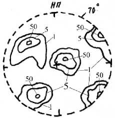
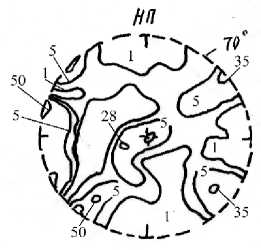
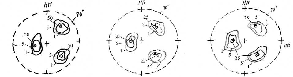
The results of the X-ray analysis are presented in fig. 1–5. The formation of the rolling texture of the central layers of the “group 1” generally has the similar character to the one described in earlier works [22–24]. The main difference of the obtained results from the previous studies is that the orientation of the “group 1” deformed single crystals is single-component. Fig. 1, 2 show {110} straight pole figures (SPF) from the central layers of the Fe – 3 % Si alloy of the specified group, rolled with the reduction rate of 35, 55 and 85 %.
The analysis shows that orientation of Fe – 3 % Si (110) [ hkl ] alloy is one-component: the samples with (110) [112] ideal orientation, at the reduction rate of 35 % have the orientation close to (112) [351] (fig. 1, a ); the samples with (110) [111] ideal orientation have the orientation close to (326) [661] (fig. 2, a ). The latter sample also has dispersion around the transverse rolling direction.
The further increase of deformation rate reduces dispersion and almost does not change the orientation (fig. 1, b and 2, b ).
The initial sample with (110) [112] ideal orientation, at the reduction rate of 85 %, has the orientation of the plane between (112) and (111); at the same time, it is slightly shifted counterclockwise from the [110] axis and can be recorded as (234) [562] (fig. 1, c). When the sample with (110) [111] ideal orientation is deformed at the reduction rate of 85%, (112) [110] orientation is one-component (fig. 2, c).
The formation of (110)[ hkl ] rolling texture of central layers of Fe – 3 % Si alloy (groups 2 and 3), deflected along (110) plane towards the rolling direction of 7 and 5 degrees respectively, in general has a similar character with the ones described in the earlier works. The scattering of the main orientations and the appearance of other weak components determine the peculiarities of the texturing results in groups 2 and 3.
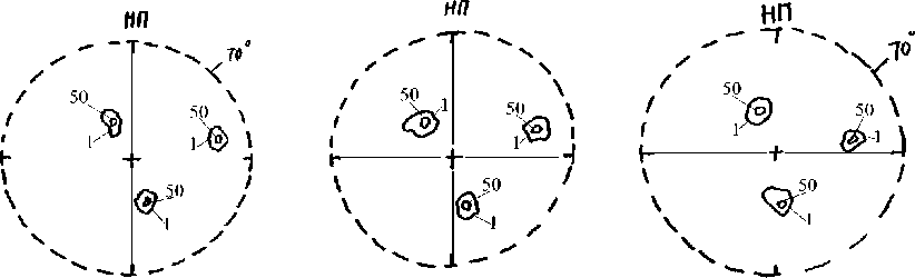
а b c
Fig. 1. Straight pole figures of the central layers of the samples ( а , b , c ) of Fe – 3 % Si (110) [ hkl ] cold rolled alloy with the initial (110) ideal orientation; with a deflection of 8 degrees from the (110) plane towards the rolling direction; rolled on the laboratory rolling mill with the rolls diameter of 90 mm; the reduction rate: а – 35 %, (112) [351] orientation; b – 55 %, (112) [35 1] orientation; c – 85 %, (234) [562] orientation
Рис. 1. Прямые полюсные фигуры (110) центральных слоев образцов ( а , б , в ) холоднокатаного сплава Fe – 3% Si (110)[ hkl ] с исходной идеальной ориентировкой (110), с отклонением от плоскости (110) в сторону направления прокатки на 8 градусов, прокатанных на лабораторном прокатном стане с диаметром валков 90 мм, со степенью обжатия:
а – 35 %, ориентировка (112) [351] ; б – 55 %, ориентировка (112) [35 1] ;
в – 85 %, ориентировка (234) [562]
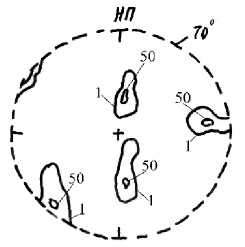
b
c
а
Fig. 2. Straight pole figures of the central layers of the samples ( а , b , c ) of Fe – 3% Si (110)[ hkl ] cold rolled alloy with the initial (110) ideal orientation; with a deflection of 8 degrees from the (110) plane towards the rolling direction; rolled on the laboratory rolling mill with the rolls diameter of 90 mm; the reduction rate: а – 35 %, (326) [661] orientation; b – 55 %, (335) [110] orientation; c – 85%, (112) [110] orientation
Рис. 2. Прямые полюсные фигуры (110) центральных слоев образцов ( а , б , в ) холоднокатаного сплава Fe – 3% Si (110)[ hkl ] с исходной идеальной ориентировкой (110), с отклонением от плоскости (110) в сторону направления прокатки на 8 градусов, прокатанных на лабораторном прокатном стане с диаметром валков 90 мм, со степенью обжатия:
а – 35 %, ориентировка (326) [661] ; б – 55 %, ориентировка (335) [110] ;
в – 85 %, ориентировка (112) [110]
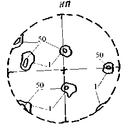
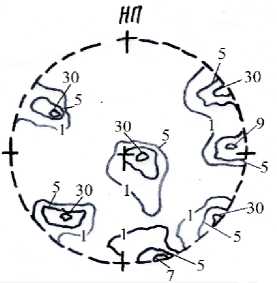
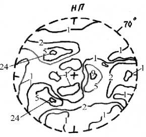
The peculiarities of texturing are influenced by the rolling conditions and the initial crystallographic orientation of the initial samples. The results of the radiographic analysis of the rolling groups 2 and 3 are presented in fig. 3–5. The analysis of pole figures was carried out similarly to the first group. The data is presented in the table below.
Thus, in the process of formation of (110) [hkl] rolling texture of the Fe – 3% Si alloy central layers with the deflection of 8 degrees from (110) plane towards the rolling direction, the following results were obtained.
In all cases, the orienta t ion appeared to be one-component; in the case of [112] initial direction, it is close to [562] direction; in the case of [111] initial direction, it is close to [110] direction.
а
b
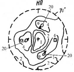
Fig. 3. Straight pole figur e s of the central layers of the samples ( а , b , c ) of Fe – 3% Si (110)[ hkl ] cold rolled alloy with the initial (110) [331] ideal orientation; with a deflection of 7 degrees from the (110) plane towards the rolling direction; rolled on the laboratory rolling mill with the rolls diameter of 90 mm; the reduction rate: а – 35 %, (221) [341] orientation; b – 55 %, (790) [972] orientation;
c – 85 %, orientation▲ – (111) [110], □ – (010) [100]
а
Рис. 3. Прямые полюсные фигуры (110) центральных слоев образцов ( а , б , в ) холоднокатаного сплава Fe – 3% Si (110)[ hkl ] с исходной идеальной ориентировкой (110) [331] , с отклонением от плоскости (110) в сторону направления прокатки на 7 градусов, прокатанных на лабораторном прокатном стане с диаметром валков 90 мм, со степенью обжатия:
a – 35 %, ориентировка (221) [341] ; б – 55 %, ориентировка (790) [972] ;
в – 85 %, ориентировка ▲ – (111) [110] , □ – (010) [100]
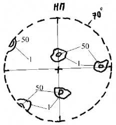
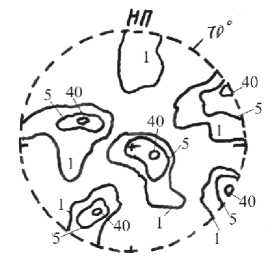
b c
Fig. 4. Straight pole figures of the central layers of the samples ( а , b , c ) of Fe – 3 % Si (110) [hkl] cold rolled alloy with the initial (110) [551] ideal orientation; with a deflection of 7 degrees from the (110) plane towards the rolling direction; rolled on the laboratory rolling mill with the rolls diameter of 90 mm; the reduction rate: а – 35 %, (331) [551] orientation; b – 55 %, (331) [110] orientation; c – 85 %, (122) [0 11] orientation
Рис. 4. Прямые полюсные фигуры (110) центральных слоев образцов ( а , б , в ) холоднокатаного сплава Fe – 3% Si (110)[ hkl ] с исходной идеальной ориентировкой (110) [551] , с отклонением от плоскости (110) в сторону направления прокатки на 7 градусов, прокатанных на лабораторном прокатном стане с диаметром валков 90 мм, со степенью обжатия:
a – 35 %, ориентировка (331) [551] ; б – 55 %, ориентировка (331) [110] ;
в – 85 %, ориентировка (122) [0 11]
b
а
c
Fig. 5. Straight pole figures of the central layers of the samples ( а , b , c ) of Fe – 3 % Si (110)[hkl] cold rolled alloy with the initial (110) [551] ideal orientation; with a deflection of 5 degrees from the (110) plane towards the rolling direction; rolled on the laboratory rolling mill with the rolls diameter of 90 mm; the reduction rate: а – 35 %, (332) [110] orientation; b – 55 %, orientation▲ – (111) [110];
c – 85 %, orientation ▲ – (111) [110]
Рис. 5. Прямые полюсные фигуры (110) центральных слоев образцов ( а , б , в ) холоднокатаного сплава Fe – 3% Si (110)[ hkl ] с исходной идеальной ориентировкой (110) [551] , с отклонением от плоскости (110) в сторону направления прокатки на 5 градусов, прокатанных на лабораторном прокатном стане с диаметром валков 90 мм, со степенью обжатия:
а – 35 %, ориентировка (332) [110]; б – 55 %, ориентировка ▲ – (111) [110];
в – 85 %, ориентировка ▲ – (111) [110]
Radiographic analysis of the Fe – 3 % Si alloy rolling groups 1–3
|
Group |
Figure |
Initial ideal orientation |
Deflection from (110) plane [degrees] |
Orientation after deformation, % |
||
|
35 |
55 |
85 |
||||
|
Preliminary |
Intermediate |
Final |
||||
|
1 |
1 |
(110) [112] |
8 |
(112)[351] |
(112) [351] |
(234) [562] |
|
2 |
(110) [111] |
8 |
(326) [661] |
(335) [110] |
(112) [110] |
|
|
2 |
3 |
(110) [331] |
7 |
(221) [341] |
(790) [972] |
(111) [110] (010) [100] |
|
4 |
(110) [551] |
7 |
(331)[551] |
(331) [110] |
(122) [011] |
|
|
3 |
5 |
(110) [551] |
5 |
(332) [110] |
(111) [110] |
(111) [110] |
The analysis of texturing during the rolling process of single crystals of groups 2 and 3 showed that there is a similarity in texture formation. The main orientation in all the cases is (111) [110] , i. e. the single crystal rotates around [110] crystallographic direction, close to the direction of rolling.
The difference between the analysis results concerning the alloys of groups 3 and 2 is the following: in the first case, a one-component (111) [110] orientation is formed, while in the second case almost always there is another weak orientation. It must be noted, that a one-component (111) [110] orientation is formed in case of a small reduction rate during one rolling, whereas an increase in reduction leads to a two-component orientation.
Conclusion. The crystallographic texture determines the service structurally dependent properties of crystalline materials and contributes to the achievement of an opti- mum level of physical and mechanical properties. During cold rolling, the crystal lattice is reoriented throughout the entire volume of the single crystal. The geometry of it depends on the initial orientation and the active slip system, determined by the Schmid’s factor, the maximum value of which reaches 0.5.
It must be noted that during rolling, the texture of the central layer of group 1 single crystals is described by a single-component orientation. When the (110) plane deflects by an angle φ = 8°, the Schmid’s factor (S) for the slip system ( 123 ) [111] - S 1 = 0.46 is larger than for the slip system ( 213 ) [111] - S 2 = 0.38. As a consequence, the active slip system is (123) [11 1] , which leads to the appearance of one-component orientation (234) [562] in the central layers, deflected from the rolling plane around the transverse rolling direction, due to the action of symmetric slip systems.
References Formation features of the central layers of the alloy Fe – 3 % Si (110)[hkl] rolling textures
- Nye J. Fizicheskie svoistva kristallov [Physical properties of crystals]. Moscow, Mir Publ., 1967, 385 p. (In Russ.).
- Sirotin Y. I., Shaskol'skaya M. P. Osnovy kristallofiziki [Basics of crystal physics]. Moscow, Nauka Publ., 1979, 639 p. (In Russ.).
- Talashkevich I. P., Mishnev S. V., Slavov V. I. [Symmetry textures in parallel rolling]. Tez. dokl. III Vsesoyuznoi konferentsii po teksturam i rekristallizatsii v metallakh i splavakh [Thesis report III All-Union conference on textures and recrystallization in metals and alloys]. Krasnoyarsk, KrPI, 1980, P. 12 (In Russ.).
- Talashkevich I. P., Mishnev S. V. [Texture formation during differential rolling of iron]. Tez. dokl. Vsesoyuz. konf. “Povyshenie dolgovechnosti i nadezhnosti mashin i privodov” [Thesis report All-Union conference ‘Increased durability and reliability of machines and drives’]. Kuibyshev, KPI, 1981, P. 354 (In Russ.).
- Mishnev S. V., Talashkevich I. P., Durnev V. D. [Differential rolled metal sheet technologies]. Vestnik KGTU. Mashinostroenie. 1999, P. 66–73 (In Russ.).
- Durnev V. D., Talashkevich I. P. Simmetriya v tekhnologii [Symmetry in technology]. St. Petersburg, Politekhnik Publ., 1993, 256 p. (In Russ.).
- Penelle et Lacombe Les Texturs de Lamlnage. Acta Metallurcica. 1968, Vol. 16, P. 346–351.
- Shubnikov A. V., Koptsik V. A. Simmetriya v nauke i iskusstve [Symmetry in the science and art]. Moscow, Nauka Publ., 1972, P. 399 (In Russ.).
- Koptsik V. A. [Principles of symmetrizationasymmetry of Shubnikov-Curie for the composite physical systems]. Problemy sovremennoi kristallografii. Sb. pamyati A.V. Shubnikova. Moscow, Nauka Publ., 1975, P. 42–60 (In Russ.).
- Mishnev S. V. [Determination of the forms of stress tensors based on the Curie principle]. Vestnik KGTU. Mashinostroenie. 1999, No. 15, P. 184–189 (In Russ.).
- Volodin P. A., Mishnev S. V. Talashkevich I. P. [Expanding the boundaries of the applicability of the principle of Hermann-Herman]. Vserossiiskaya nauchnoprakticheskaya konferentsiya molodykh uchenykh “Innovatsii i aktual'nye problemy tekhniki i tekhnologii” [All-Russian scientific-practical conference of young scientists "Innovations and Challenges of engineering and technology"]. Saratov, 26–29 October 2010. 2010, Vol. 2, P. 126–130 (In Russ.).
- Druzhinin V. V. Magnitnye svoistva elektrotekhnicheskoi stali [Magnetic properties of electrical steel]. Moscow, Energiya Publ., 1974, 240 p. (In Russ.).
- Hgun Hu and R. S. Cline Rolling Texture in Aluminium-Iron Single Crystals // Trans of The Metallurgical Society of AIME., 224, P. 784.
- Avramov Y. S., Naumann G. [Formation of the recrystallization texture during the rolling of single crystals of Fe – Si (3%) of a single crystal (110) in different crystallographic directions]. Neorganicheskie materially. 1967, Vol. 3, No. 7, P. 1170–1173 (In Russ.).
- Avramov Y. S., Molotilov B. V., Naumann G. [The ratio between the textures of deformation and recrystallization during the rolling of single crystals (110) of transformer steel in different directions]. FMM. 1966, Vol. 21, No. 5, P. 740–744 (In Russ.).
- Opinsky A. J., Smoluchowski R. The Crystallographic Aspect on Slip Body-Centered Cubic Single Crystals, 2. Interprenanion on Experiments // Journal of Applied Physics. 1951, Vol. 22, No. 12, P. 1488–1492.
- Hu H. Otzhig kremnistogo zheleza. Vozvrat i rekristallizatsiya metallov [Siliceous iron annealing. Return and recrystallization of metals]. Moscow, Metallurgiya Publ., 1966, P. 273–326 (In Russ.).
- Savinskaya A. A., Gol'dshtein V. Ya. [Investigation of the heterogeneity of textural formation during rolling of silicon iron single crystals]. Materialy 3-ei Vsesoyuznoi konferentsii po teksturam i rekristallizatsii v metallakh i splavakh [Materials of the 3rd All-Union conference on textures and recrystallization in metals and alloys]. Krasnoyarsk, KrPI, 1982, P. 92–99 (In Russ.).
- Kazadzhan L. B., Sil'nikova E. F., Dergach V. V. [Asymmetry of deformation textures of siliceous iron single crystals]. Izvestiya AN SSSR, seriya fizicheskaya. 1979, Vol. 43, No. 7, P. 1385–1387 (In Russ.).
- Gorelik S. S., Rastorguev L. N., Skakov Y. A. Rentgenograficheskii i elektronno-opticheskii analiz [Xray and electron-optical analysis]. Moscow, MISIS Publ., 2002, 360 p. (In Russ.).
- Borodkina M. M., Spektr E. N. Rentgenograficheskii analiz tekstur metallov i splavov [X-ray analysis of the textures of metals and alloys]. Moscow, Metallurgiya Publ., 1981, 272 p. (In Russ.).
- Druzhinin V. V. [On the anisotropy of the brittleness of silicon steel sheet]. FMM. 1959, Vol. 7, No. 2, P. 278–283 (In Russ.).
- Kudryavtsev I. P. Tekstury v metallakh i splavakh [Textures in metals and alloys]. Moscow, Metallurgiya Publ., 1966, P. 370 (In Russ.).
- Vasil'ev V. V., Protasov V. D., Bolotin V. V. Kompozitsionnye materialy: Spravochnik [Composite materials: handbook]. Moscow, Mashinostroenie Publ., 1990, 520 p. (In Russ.).
