Forward Error Correction Convolutional Codes for RTAs' Networks: An Overview

Автор: Salehe I. Mrutu, Anael Sam, Nerey H. Mvungi
Журнал: International Journal of Computer Network and Information Security(IJCNIS) @ijcnis
Статья в выпуске: 7 vol.6, 2014 года.
Бесплатный доступ
For more than half a century, Forward Error Correction Convolutional Codes (FEC-CC) have been in use to provide reliable data communication over various communication networks. The recent high increase of mobile communication services that require both bandwidth intensive and interactive Real Time Applications (RTAs) impose an increased demand for fast and reliable wireless communication networks. Transmission burst errors; data decoding complexity and jitter are identified as key factors influencing the quality of service of RTAs implementation over wireless transmission media. This paper reviews FEC-CC as one of the most commonly used algorithm in Forward Error Correction for the purpose of improving its operational performance. Under this category, we have analyzed various previous works for their strengths and weaknesses in decoding FEC-CC. A comparison of various decoding algorithms is made based on their decoding computational complexity.
FEC, Convolutional Codes, Real Time Applications, Burst errors, Sequential Decoding, Viterbi Decoding
Короткий адрес: https://sciup.org/15011318
IDR: 15011318
Текст научной статьи Forward Error Correction Convolutional Codes for RTAs' Networks: An Overview
-
I. Introduction
Forward error correction (FEC) is a digital channel coding algorithms used in data communication to correct data transmission errors without retransmission [1] . This scheme is divided into block codes and convolutional codes [2] , [3] , [4] . FEC Convolutional Codes (FEC-CC) were introduced by Elias in 1955 as an alternative to the class of block codes and they are widely used in many applications such as mobile communication, digital video, and satellite communication to achieve reliable data transfer [5] , [6] , [7].
In recent years, the world has witnessed a large increase in the use of modern wireless mobile devices that run multimedia applications [8] . Hence, there is rapid growth of e-business, higher data transmission rates, larger bandwidth demand and enhanced networks reliability to support the exponentially growing data transmission needs. The 2013 International Telecommunication Union (ITU) statistics showed that global mobile cellular subscription reached 6.8 billion users worldwide, with global penetration rate of 96
percent, 128 percent penetration rate in developed world and 89 percent in developing countries [9] . According to Cisco Visual Networking Index, global mobile data traffic reached 885 petabytes after offloading 429 petabytes per month to fixed network at the end of 2012. This is 96 percent traffic increase before offloading and 70 percent increase after offloading [10] .
To cope with the requirement of bandwidth for data transmission, average mobile network speeds have increased more than two folds in the year 2012. The global average mobile network downstream increased from 248 kilobits per second (kbps) in 2011 to 526 kbps in 2012. Global average mobile network connection speed for smart phones grew from 1211 kbps in 2011 to 2064 kbps in 2012. The tablets on the other hand, grew from 2032 kbps to 3683 kbps [10] . This trend of constant increase in transmission rates of mobile wireless transmission creates another problem that requires immediate attention. The formation of burst errors in data transmitted due to high transmission speed [11] and the fact that error conditions of wireless media vary widely in fading channels creates burst errors decoding challenge to FEC codes that manages the errors at the receiving device [12] .
N. Hajlaoui et al. [13] , presented experimental results on frame aggregation enhancement in IEEE 802.11n WLANs which showed that aggregation sometimes degrades quality of service of some RTAs by adding more jitter and delay in data transmission. Another experimental results done by Alaa [14] showed that even cloud computing sometimes do not offer the required quality of service to support RTAs due to increase in computation and transfer time. Similarly, it has been reported that Internet networks sometimes fail to provide the quality of service that is needed for RTAs interaction through groupware [15] , [16] .
This paper investigates Convolutional Codes as one of the most commonly used algorithm in FEC and an alternative to ARQ mechanisms. The investigation aims to improve the FEC-CC’s operational performance to support RTAs networks.
The remaining part of this paper is organized in the following manner: Section II of this paper describes the binary Convolution Codes, the encoding and decoding processes. It also analyses, evaluates and compares the decoding computational complexity challenges of
Sequential and Viterbi algorithms. Section III, discusses various techniques used to enhance performance of binary convolutional codes to improve its operational performance with their impacts to data communication systems. Section IV explains the key observations made. Section V concludes these efforts and gives recommendations for future research.
II. Binary Convolutional Codes
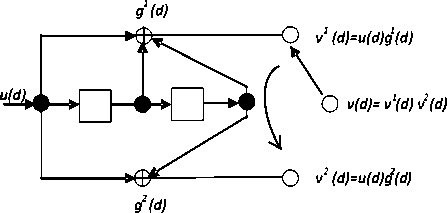
Fig 1: (2, 1, 2) Convolutional encoder
Convolutional codes are popular class of coders with memory, where the current output data block from the encoder is not only a function of the current input block but also of other previous data blocks. Binary convolutional codes are commonly defined by three parameters, ( n , k ’ m ) where n is a number of output bits (bits in a codeword) from the encoder and, k is a number of input bits to the encoder at a time while m is a number of memory size used in that encoder. Therefore,
the hardware connection of the shift register taps to the modulo-2 adders. A generator vector represents the position of the taps for an output. A “1” represents a connection and a “0” represents no connection.
( n , k , m ) binary convolutional code
generates n
encoded data bits for every k data bits, where n > k .
( n k ) is a number of redundancy bits
added to data
bits. The redundancy bits are used by decoder to recover the distorted information. Factor k n is a code rate r of that particular convolutional encoder. Convolutional encoder is also characterized by its constraint length ( K ) which is given by; K = m + 1 where m is the memory stage of the used shift register. Constraint length
A. Encoding Binary Convolutional Codes
Apart from the generator sequences used in the previous section, state, tree and trellis diagrams demonstrate and provide better understanding of internal operations and processes of a binary convolutional encoder and decoder.
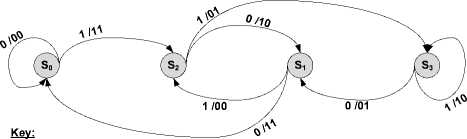
State diagram of a (2, 1, 2) binary convolutional encoder can be treated as a finite state machine where the contents of the shift register represents the states. The
v output of a code block t at time t depends on the
s current state
u t and the data block t . Each change of
relates to the
depends. Fig.
encoder with
. Z- = 1 input length K = 3 .
number of bits upon which the output 1 shows a standard ( 2 ,1,2 ) convolutional rate r = 12 , where output n = 2 ,
, memory size m 2 and constraint . For each input bit, there are 2 output bits,
ss state from t to t+1 is associated with the input of a data block and the output of a code block. The state diagram is obtained by drawing all possible contents (states) of the registers with arrows that show all possible state transitions from the current state to the next state. In Fig. 2, nodes are all possible states of the standard encoder shown in Fig.1 with labeled arrows (inputs/outputs that
which depend on the previous 2 input bits. The encoder consists of an m-stage shift register together with modulo-2 adders and a multiplexer for serializing the encoder outputs.
If the input sequence is u = ( u 0, ux , u 2 ••••) , the two
uv correspond to t t
) indicating the state transitions. The
encoder maps the input block of data to output block of
codewords. Table I, Fig. 2, Fig. 3, and Fig.4 show an
example
of encoding (1 1 0 1) to
encoder output sequences v 1 = ( v 1 , v 1 , v 1 ....) and 2 222
v = ( v 0 , v j , v 2 ....) are equal to the convolution of the input sequence u with the two code generator sequences g 1 = (1,1,1) and g 2 = (1,0,1) i.e., the encoding equations are v 1 = u * g 1 and v 2 = u * g 2 where * is a convolution operation. Generator representation shows
(11 01 01 00) using different presentation diagrams.
The white nodes in Fig. 3 and Fig. 4 show the encoding path of the same data.
Node content corresponds to a shift register contents:
S 0 = 00, S 1 =01, S 2 =10 and S 3 =11.
Path labels:
u/v1v2 -input/output(Data/Codeword)
Fig 2: (2, 1, 2) binary convolutional encoder state diagram
Table I: Encoding (1-1-0-1) to (11-01-01-00)
|
Input bit “u” (data) |
Input State |
Output bits “v1v2” (Codewords) |
Next State |
|
1 |
S 0 |
11 |
S 2 |
|
1 |
S 2 |
01 |
S 3 |
|
0 |
S 3 |
01 |
S 1 |
|
1 |
S 1 |
00 |
S 2 |
It is customary to start and terminate the encoding process at all zero state s 0 (00), therefore, in actual implementation of binary convolutional encoder tail bits are added to input data to push the encoder memory to all zero state. This fact makes the binary convolutional encoder to have a design rate and an implementation rate whereby implementation rate is always smaller than the actual design rate.
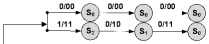
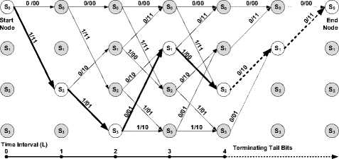
Tree diagram can also be used to demonstrate the encoding and decoding processes. Referring to Fig.3 the encoding process starts from left towards the right with time interval L , the nodes are the states of the register { «Ш10,11 } that corresponds to { s 0 . s | . s 2 , s 3 ! respectively.
4 Terminating Tail Bits
Key
Path branch labels:
u/v1v2 – input/output (data/codeword)
Fig 3: Tree diagram of (2, 1, 2) binary convolutional code
A code tree of ( n , k , m ) binary convolutional code presents every codeword as a path on a tree. For input sequences of length L bits, the code tree consists of
2 kL
paths; this makes it a bit difficult to manage when working with long input blocks.
Key
Path branch labels:
u/v1v2 – input/output (data/codeword)
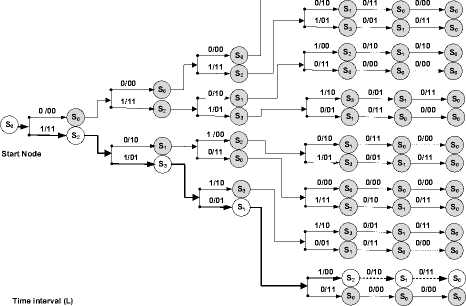
Fig 4: Trellis diagram of (2, 1, 2) binary convolutional encoder
Trellis diagrams as named by Forney [17] and shown in Fig. 4 is a structure obtained from a code tree by 2m nodes kL to be shown and the same 2 paths in the trellis diagram at each time interval.
-
B. Decoding Binary Convolutional Codes
The encoded kL codewords bit sequences are then modulated to relevant signals (waveforms) for transmission through a medium. The characteristics of the medium introduce noise to the sent signals and distort them [18] . The distorted signal is said to have transmission errors. Transmission errors in digital communication can occur in a single bit where a bit in a data block is distorted or multiple bits where many but not consecutive bits in a data block are distorted or burst bits where many and consecutive bits are distorted in a data block [19] . Transmission errors cause the receiver to receive different data from the sent one, hence the need to have a mechanism of identifying errors and estimating the original sent data to correct the transmission errors.
Estimation mechanism at the receiving end is conceptually divided into two main parts: demodulation and decoding [20] . The demodulator transforms the received waveforms into discrete signals for the decoder to determine the original data sequences. If the discrete demodulated signal is binary (i.e. 0 and 1), then the demodulator is called a hard-decision demodulator and its subsequent decoder is also termed a hard-decision decoder. If the demodulator passes analog (i.e., discretein-time but continuous-in-value) or quantized outputs to the decoder, then it is called a soft-decision demodulator and its subsequent decoder is also called soft-decision decoder. Uncorrected or wrongly estimated data by demodulator are forwarded to a decoder for further transmission error suppression. The remaining part of this section discusses the Fano and Stack sequential algorithms; and the Viterbi algorithm for decoding binary convolutional codes. In general, the decoding process of FEC codes with errors is more difficult than the encoding process at the sender [18] .
-
C. Fano algorithm
Decoding binary convolutional codes using Sequential algorithm was first introduced by Wozencraft in 1957 [21] , [22] . In 1963, Fano [23] extended the algorithm by improving decoding efficiency. Fano algorithm can be well described by analogy. Imagine being given some guidelines to go to a place using landmarks, but the guidelines were poorly given and sometimes landmark is not recognized giving a feelling of being on a wrong path. Then one stops and backtracks to a point where one recognizes a landmark and takes an alternative path until the next landmark is seen. Eventually, in this fashion one manages to reach the destination. In this process, one may back track several times depending on how good the guidelines were. This is quite similar to searching on a tree (refer to the tree diagram in Fig. 3). Fano decoder allows both forward and backward movements through the trellis or tree. The decoder keeps track of its decisions and tallies it up. If the tally increases faster than a given threshold value, then the decoder drops that path branch and retraces back to the last divergence point where the tally was below the threshold and then consider an altenative branch.
Fano Algorithm requires small memory to keep track of its three paths in a tree, the current path, immediate predecessor and one of its succesor path. This information enables the algorithm to move forward and backward using its dynamic threshold. Althogh Fano algorithm has very high node computation load but it has less evaluation cost compared to that of the stack algorithm [24] discussed in the next subsection.
Considering a binary convolutinal encoder discribed above, Fano algorithm suffers an exhaustive 2 kL tree searches for decoding kL encoded data bit sequences. The exhaustive tree search composes a computational complexity in the order of (2 ) , where k is a number of parralel input data to the binary convolutional encoder at one time interval and L is the number of time intervals. The computational complexity of the decoding process using this algorithm becomes worse if multiple or burst transmission errors are experienced, because they increase the probability of the algorithm backtracking and sometimes with the posibility of revisiting same paths more than once [20] . Furthermore, complexity of this algorithm increases with the increase of length L of a codeword sequence, thus, this method is effective for short block length. However, increasing the number of input bits k at a time improves the code rate and hence the data throughput. On the other hand, increasing of input bits k at a time, increases the Fano algorithm decoding complexity. This algorithm has variable computational delay hence not attractive for most of the delay sensitive RTAs [25] , [26] .
In implementation, Fano algorithm has been improved in different ways to improve its operational performances. Two uni directional or two bidirectinal parrellel Fano decoders have been designed to work together [25] , [26] , [27] , [28] .
-
D. Stack Algorithm.
The work done by Fano was further developed by Zigangirov [29] , and then by Jelinek [30] who proposed the sequential stack algorithm. In spite of the fact that Stack algorithm is different in its design from the Fano algorithm, it behaves in the same way as the Fano algorithm in a tree search. It has been proven that both algorithms visit about the same set of nodes and paths in the decoding process [20] , [31] . Stack algorithm uses a stack utility to store the decoded data, and therefore, it needs a sorting procedure to rearange the stack contents when the system is backtracking from time to time. The sorting process is time consumming and hence Stack algorithm is more costly than a non sorting fano algorithim [20] , [24] . Contrary to Fano algorithm which may revisit a path several times and hence higher computational complexity, the Stack algorithm visits a path once. However, Stack algorithm has also a stack size drawback in that if a large number of paths are examined during the search process, a stack overflow can happen which simply discards paths with the smallest function value. This fact degrades the algorithm performance if the discarded path happens to be an early predecessor of the optimal code path [32] , [33] . Recent studies show the use of hybrid stack algorithms in multiple antennas at transmitter and receiver, multiple-input multiple-output (MIMO) wireless communication system for wireless transmission error detection only and not for transmission error correction [34] . The main disadvantage of stack algorithm is time delay because of backtracking [34] , [35] . This shortcoming makes the sequential algorithims too oblivion compared to other algorithims such as Virterbi algorithm [36] , [37] .
-
E. Viterbi Algorithm
Viterbi decoding was introduced by Viterbi in 1967 [38] . It is probably the most popular and widely adopted in practice decoding algorithm for Convolutional codes [6] . This algorithm is also the best known implementation of the maximum likelihood decoding [20] , [39] , [40] . The Viterbi decoder examines an entire received data sequence of a given length at a time interval on a trellis, then computes a metric for each path and makes a decision based on this metric. One of the common metric used by Viterbi Algorithm for paths comparison is the Hamming distance metric, which is a bit-wise comparison between the received codeword and the allowable codeword, Table IIA and Table IIB show how the calculation is done. The Hamming metrics are calculated for each path branch in every time interval and then cumulatively added to get a total path metric of up to time L or L + m .
There are two methods of calculating a Hamming distance metric; Table IIA describes a method where the surviving path with the highest total Hamming metric is considered to be the final winner. Table IIB describes the opposite method where the path with the lowest total metric is the final winner. The decoding example in this paper (Fig. 5) uses the method described in Table IIA.
Table II a: Hamming metric calculation
|
Received Codeword |
Valid Codeword 1 |
Hamming Metric 1 |
Valid Codeword 2 |
Hamming metric 2 |
|
11 |
00 |
0 |
11 |
2 |
|
01 |
11 |
1 |
00 |
1 |
|
01 |
01 |
2 |
10 |
0 |
Table II b: Hamming metric calculation
|
Received Codeword |
Valid Codeword 1 |
Hamming Metric 1 |
Valid Codeword 2 |
Hamming metric 2 |
|
11 |
00 |
2 |
11 |
0 |
|
01 |
11 |
1 |
00 |
1 |
|
01 |
01 |
0 |
10 |
2 |
In decoding the received binary convolutional codewords using trellis diagram, all paths are followed until two or more paths converge on one node. The paths with higher metric (also known as survivor paths) are kept and those with lower metric are discarded. The surviving paths are further compared again and again whenever they converge in a node to get a winning 2m survivor
S paths can be forced to converge at state 0 if m zeros were added as terminating tail bits to the binary convolutional encoder (see Fig. 4).
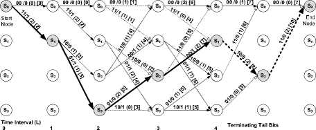
Fig. 5 shows an example of a Viterbi algorithm in decoding codeword stream obtained in Table I (i.e. 1101-01-00), received with a single transmission error in position 3 (i.e. 11-11-01-00) to (1-1-0-1). Decoding is the reverse process of the encoding process shown in Fig. 4 and the Viterbi decoder starts from state S0. The received codewords (on the top line of Fig. 5) are compared bit by bit with the allowed codewords obtained from the Viterbi decoder using the method described in Table IIA to obtain the branch metrics. In Fig. 5, path branch metrics are put in path labels using a round bracket i.e. (x). The cumulative path metrics are put in a square bracket i.e. [x]. The decoding process in Fig. 5 follows the following four steps:
-
• The allowed path codeword is compared with the received codeword for that particular time interval and the results put in a round bracket (i.e. (x)) as path branch metric.
-
• The path cumulative hamming metric of the current path branch is found by adding the obtained branch metric to the cumulative path metric of the immediate predecessor surviving path. Note that, the first path branches from the starting node do not have immediate path branch predecessor, therefore, the cumulative branch path metric of their immediate predecessor is zero.
-
• The cumulative path branch metrics of the branches which converge in a node are
compared. The branch path with higher cumulative branch path metric is a survivor path and kept while other paths are discarded. If the converging paths have the same cumulative path metrics, then they are all kept. Step one to three is recurring at each time interval L of the trellis diagram.
-
• Eventually, the cumulative hamming metrics of all the surviving paths are compared. The surviving path with highest hamming metric is the final winner and data are extracted from this path. If more than one path has the same highest cumulative path metrics then one of the surviving paths with highest cumulative path metric is arbitrarily selected as a final winner.
Out of the 2 kL exhaustive searches of different paths on trellis, Viterbi Algorithm reduces this number by searching one stage at a time in the trellis diagram. In each node of the trellis there are 2 k calculations and the number of nodes per stage in a trellis is 2 m . Since all the stages in the trellis are L + m , then the complexity of Viterbi Algorithm is reduced to the order of(2 ( k + m ) ( L + m )). It should also be noted that the time interval L is now a linear factor and not an exponent factor in complexity. The algorithm eliminates least likely trellis path at each data decoding stage and therefore the reduction of decoding complexity with early rejection of unlikely surviving paths [42] . Unlike Stack algorithm in a stack overflow, Viterbi algorithm maintains all the paths which are likely to be winning survival paths [33] .
Single bit Error
Received 11
Codewords
Key
Labels:
xx/y - Allowed Codeword/Output
(x) - Branch path Hamming Metric
[x] - Cumulative path Hamming Metric
Paths:
- Paths with lower Hamming metrics (Non surviving paths are discarded)
- Paths with higher Hamming metrics(Surviving paths are kept)
- Winning surviving path
Fig 5: Trellis diagram of a Viterbi decoder in decoding the received codewords with error in position 3 (i.e. 11-11-01-00) to (1-1-0-1)
An increase in m improves error correction capabilities of binary convolutional codes [43] , [7]. However, it should be noted that Viterbi Algorithm has m as an exponent factor on its decoding computational complexity, hence the maximum practical limit of length of K is 10 [41] . Contrary to Viterbi Algorithm,
Sequential decoding can achieve a desired bit error probability when a sufficiently large constraint length is taken for the binary convolutional code. These specific characteristics make the sequential decoding algorithms useful for special type of applications [20] .
-
F. Computational Complexity Comparison of Sequential
Vs Viterbi Algorithms
Let us assume that both algorithms decode the received codewords encoded by a binary (2, 1, 2) Convolutional encoder where the input k and memory length m are constants 1 and 2 respectively. Since Fano and Stack algorithms have proven to visit almost the same nodes and paths in decoding, then they have almost the same order of (2 ) computational complexity. Viterbi
( k + m )
algorithm has the order of ( ( + m)) Computational complexity. Table III compares the decoding computational complexity of the Sequential and Viterbi algorithms.
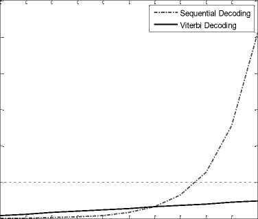
Fig. 5 shows the results of the computational complexity of the Sequential and Viterbi algorithms simulated using MATLAB software. The simulation results in Fig. 5 show that, an increase in block length L causes an exponential increase in decoding computational complexity of the Sequential algorithms. Incomparably, Viterbi algorithm has a small linear increase of the decoding computational complexity. Algorithm with high computational complexity will practically be too slow to support RTAs.
Table III: Computational Complexity of Sequential and Viterbi decoding
|
Increase in Input Block length (L) |
Sequential decoding Complexity (2L) |
Viterbi decoding Complexity (16 +8L ) |
|
1 |
2 |
24 |
|
2 |
4 |
32 |
|
3 |
8 |
40 |
|
4 |
16 |
48 |
|
5 |
32 |
56 |
|
6 |
64 |
64 |
|
7 |
128 |
72 |
|
8 |
256 |
80 |
|
9 |
512 |
88 |
|
10 |
1024 |
96 |
Decoding Computational Complexity
0 1 2 3 4 5 6 7 8 9 10
Increase in Data Block length (L)
Fig 6: Comparison of Sequential and Viterbi decoding computational Complexity
-
III. Enhensing Convolutional Decoding
In general, binary convolutional decoding algorithms can work well with a single bit transmission error and hardly with spaced multiple bits transmission errors in a data block [43] . However, decoding binary convolutional codes is a difficult task especially when burst errors occur in a data block [18] , [44] . According to Nouh et al. [18] , decoding of error correction codes is a Non-deterministic Polynomial-time hard problem (NP-Hard problem). Therefore, the quality of a decoder highly depends on industrial requests. Sometimes few transmission errors are tolerated in favor of the reduction of the code complexity. When a high quality decoder is needed, other mechanisms such as hybrid code system or code concatenation, code puncturing and code interleaving are used to support decoders.
Ján Poctavek [45] with his research team in 2011 noted that, Hybrid codes that combine convolutional codes with other types of FEC or even Automatic Repeat Request algorithms (ARQ) are used to increase error correction capability. In hybrid codes the involved algorithms are put either in serial or parallel with the convolutional code, another good example of this can be seen in the work by T-Y. Chen et al. [46] where a Modified Incremental Redundancy with Feedback (MIRF) allows short convolutional codes to deliver bit error rate performance similar to a long block length turbo code, but with lower latency. Many other examples of this type can be seen in M. Francis and R. Greens’ contribution [47] . However, it is important to note that hybrid codes are used when individual codes or algorithms fail to meet the required quality of service.
The second alternative is to apply a code puncturing technique. Code puncturing allows an encoder-decoder pair to change their code rates r , which is the code error correction capabilities without changing their basic structure [48], [49]. Code puncturing involves deleting certain code bits. Puncturing convolutional codes was introduced by Cain, Clark and Geist in 1979 [50] and further modified by Hagenauer in 1988 [51]. These codes draw attention of many developers because of their flexibility to wireless channel. On the other hand, puncturing adjacent bits result in burst error which in turn degrades the binary convolutional encoder/decoder ability to recover lost bits [49].
Another alternative in supporting FEC to combat the effects of multiple and burst errors is the use of an interleaving utility [37] , [52] , [53] . Interleaving simply involves rearranging data bits from two or more codewords before transmission on the channel [54] . Interleaving process is done by writing data bits row-byrow into a x b matrix and reading out column-by-column before sending the data over the channel. The reverse process (de-interleaving) is performed at the receiver to get the original arrangement. This process results into each successive bits of any given codeword to have a - 1 symbols that belong to other a - 1
-
IV. Remarks and Discussion
The analysis made from the literature reviewed on FEC convolutional codes, a number of factors affecting operational performance have been observed as follows:
-
• Decoding binary convolutional codes received with errors is amongst the extremely difficult problems.
-
• Sequential algorithms have higher decoding complexity which depends on a dynamic exponential variable L (decoding block length). Decoding long block length using sequential decoder in a bad error condition results in a prohibitive amount of decoder computation overheads that may degrade quality of most RTAs.
-
• In Viterbi algorithm, block length L is a linear factor of the decoding computational complexity and has lower effect in the algorithm decoding computational complexity. Note that increase in block length L is favorable to a bad error condition.
-
• Convolutional codes work better with small code rate r , increase in number of inputs k improves the data transmission speed. However, when burst errors occur convolutional codes perform poorly without an interleaver.
-
• The use of interleaver helps decoders by converting transmission burst errors into a single bit error in each data block. However, interleaver results in higher delay.
-
• Increase in m (memory size) improves Viterbi algorithm error correcting capability. However, when constraint length K is higher than 10 the algorithm becomes impractical as it results in excessive delay due to exponential growth of its computational complexity. However, the memory size m is a fixed variable in a binary convolutional encoder.
This paper reviewed the computational challenges of the convolutional encoder-decoder with the aim to improve its operational performance in data communication networks to meet RTA’s requirements. It has been observed that improving the decoding part of the algorithm may yield better results in serving RTAs. Sequential and Viterbi algorithms for decoding binary convolutional codes were analyzed and compared to determine possible elements for improvement of binary convolutional codes. Sequential algorithms have shown high exponential increase of their decoding computational complexity and thus, too jittery to meet RTAs requirements. Exceptionally, Viterbi Algorithm has shown linear growth of its decoding computational complexity with the increase in data block length which indicates a good potential for improved performance. Therefore, future work entails the designing of an improved Viterbi algorithm to improve its operational performance.
Список литературы Forward Error Correction Convolutional Codes for RTAs' Networks: An Overview
- K. Yu, M. Gidlund, J. ?kerberg, and M. Bj?orkman, "Reliable and low latency transmission in industrial wireless sensor networks," Procedia Computer Science, vol. 5, pp. 866-873, 2011.
- S. Liumeng, "Application and Principle of Error Corrected Encoding Technology," Energy Procedia, Elsevier Ltd., vol. 13, pp. 9087-9092, 2011.
- H. Sijia and Z. Zexi, "Principles of FECs with evaluating different types of FEC used in the Internet and wireless networks," in Electronics, Communications and Control (ICECC), 2011 International Conference on, 2011, pp. 2181-2184.
- A. Mohamed, M. Abd-Elnaby, and S. A. El-dolil, "Performance Evaluation of Adaptive LDPC Coded Modulation Cooperative Wireless Communication System with Best-Relay Selection," International Journal of Digital Information and Wireless Communications (IJDIWC), vol. 4, pp. 155-168, 2014.
- S. I. Mrutu, S. Kalolo, M. Byanyuma, C. Nyakyi, and A. Sam, "Bandwidth Aware FEC Algorithms for Wireless Communication Systems," Control Theory and Informatics, vol. 3, pp. 8-13, 2013.
- M. I. García Planas, E. M. Souidi, and L. E. Um, "Decoding algorithm for convolutional codes under linear systems point of view," presented at the The 8th WSEAS International Conference on Circuits, Systems, Signal and Telecommunications (CSST '14), Tenerife, Spain, 2014.
- S. Virabtamath and G. Attimard, "Impact of constraint length on performance of Convolutional CODEC in AWGN channel for image application," International Journal of Engineering Science and Technology, vol. 2, pp. 4696-4700, 2010.
- S. Kalolo, S. I. Mrutu, C. Nyakyi, M. Byanyuma, and A. Sam, "Toward Efficient Resource Utilizations in Wireless Cellular Networks: A Case Study of Tanzania," International Journal of Electrical Electronics and Telecommunication Engineering,, vol. 44, pp. 1161-1165, 2013.
- ITU-ICT-Facts-and-Figures. (2013). The World in 2013: ICT Facts and Figures. Available: http://www.itu.int/en/ITUD/Statistics/Documents/facts/ICTFactsFigures2013.pdf
- Cisco-Visual-Networking-Index, "Global Mobile Data Traffic Forecast Update, 2012-2017," http://www.cisco.com/en/US/solutions/collateral/ns341/ns525/ns537/ns705/ns827/white_paper_c11-520862.html,, 2013.
- V. K?ivánek, "Enhancement in the Protection of Transmitted Data," International Journal of Computer Science and Network Security, vol. 8, pp. 95-98, 2008.
- M. R. Hueda, C. Rodríguez, and C. Marqués, "Enhanced-performance video transmission in multicode CDMA wireless systems using a feedback error control scheme," in Global Telecommunications Conference, 2001. GLOBECOM'01. IEEE, 2001, pp. 619-626.
- N. Hajlaoui, I. Jabri, and M. B. Jemaa, "Experimental Performance Evaluation and Frame Aggregation Enhancement in IEEE 802.11 n WLANs," International Journal of Communication Networks and Information Security (IJCNIS), vol. 5, pp. 48-58, 2013.
- A. Y. Taqa, L. S. Ng, and A. A. Joshi, "The Challenges of Using Multi Computing in Real Time Visual Applications," International Journal of Computer Science and Engineering Survey (IJCSES), vol. 2, pp. 1-14, 2011.
- J. Dyck, C. Gutwin, and D. Makaroff, "Adaptive forward error correction for real-time groupware," in Proceedings of the 17th ACM international conference on Supporting group work, 2012, pp. 121-130.
- H. Zhang, W. Jiang, J. Zhou, Z. Chen, and J. Li, "M3FEC: Joint Multiple Description Coding and Forward Error Correction for Interactive Multimedia in Multiple Path Transmission," Tsinghua Science & Technology, vol. 16, pp. 320-331, 2011.
- G. Forney Jr, "Review of random tree codes," NASA Ames Research Center, Moffett Field, CA, USA, Tech. Rep. NASA CR73176, 1967.
- S. Nouh, I. Chana, and M. Belkasmi, "Decoding of Block Codes by using Genetic Algorithms and Permutations Set," International Journal of Communication Networks and Information Security (IJCNIS), vol. 5, pp. 201-209, 2013.
- B. Forouzan, C. Coombs, and S. C. Fegan, Introduction to data communications and networking: McGraw-Hill, Inc., 1997.
- Y. S. Han and P. N. Chen, Sequential decoding of convolutional codes: Wiley Online Library, 2002.
- J. Wozencraft, "Sequential Decoding for Reliable Communications," Lab. Electron., MIT Tech. Rep, vol. 325, 1957.
- J. M. Wozencraft and B. Reiffen, Sequential decoding vol. 290: MIT Press Cambridge, MA, 1961.
- R. Fano, "A heuristic discussion of probabilistic decoding," IEEE Transactions on Information Theory, vol. 9, pp. 64-74, 1963.
- J. Anderson and S. Mohan, "Sequential coding algorithms: A survey and cost analysis," Communications, IEEE Transactions on, vol. 32, pp. 169-176, 1984.
- A. Kakacak and T. Kocak, "Design and implementation of high throughput bidirectional Fano decoding," in Industrial Electronics and Applications (ICIEA), 2013 8th IEEE Conference on, 2013, pp. 1670-1675.
- H. P. Kumar, U. Sripati, K. R. Shetty, and B. S. Shankarananda, "Soft Decision Fano Decoding of Block Codes Over Discrete Memoryless Channel Using Tree Diagram," Journal of Electrical Engineering, vol. 63, pp. 59-64, 2012.
- G. Forney Jr, "Final report on a coding system design for advanced solar missions," Contract NAS2 {3637, NASA Ames Research Center, CA, 1967.
- R. Xu, T. Kocak, G. Woodward, and K. Morris, "Throughput improvement on bidirectional Fano algorithm," in Proceedings of the 6th International Wireless Communications and Mobile Computing Conference, 2010, pp. 276-280.
- K. S. Zigangirov, "Some sequential decoding procedures," Problemy Peredachi Informatsii, vol. 2, pp. 13-25, 1966.
- F. Jelinek, "Fast sequential decoding algorithm using a stack," IBM Journal of Research and Development, vol. 13, pp. 675-685, 1969.
- J. Geist, "Search properties of some sequential decoding algorithms," Information Theory, IEEE Transactions on, vol. 19, pp. 519-526, 1973.
- S. Lin and D. J. Costello, "Error Correcting Coding: Fundamentals and Applications," ed: Prentice Hall, Englewood Cliffs, NJ, 1983.
- M. S. Ryan and G. R. Nudd, "The viterbi algorithm," Technical Report. Department of Computer Science, Coventry, UK., 1993.
- L. Liu, J. K. Wang, X. Song, and Y. H. Han, "Improved Stack Algorithm for MIMO Systems," Applied Mechanics and Materials, vol. 333, pp. 666-669, 2013.
- L. Liu, J. Wang, D. Yan, R. Du, and B. Wang, "Improved Stack Algorithm for MIMO Wireless Communication Systems," in Intelligent Computing and Information Science, ed: Springer, 2011, pp. 592-598.
- J. Hagenauer and C. Kuhn, "The list-sequential (LISS) algorithm and its application," Communications, IEEE Transactions on, vol. 55, pp. 918-928, 2007.
- I. Jacobs, "Practical applications of coding," Information Theory, IEEE Transactions on, vol. 20, pp. 305-310, 1974.
- A. Viterbi, "Error bounds for convolutional codes and an asymptotically optimum decoding algorithm," Information Theory, IEEE Transactions on, vol. 13, pp. 260-269, 1967.
- V. Gupta and C. Verma, "My Viterbi vs MATLAB Viterbi," International Journal of Engineering and Advanced Technology (IJEAT), vol. 2, pp. 389-391, 2012.
- C. Langton, "Tutorial 12 Coding and decoding with Convolutional Codes," Complex2Real. com Complex Communications Technology Made Easy, 1999.
- A. Viterbi, "Convolutional codes and their performance in communication systems," Communication Technology, IEEE Transactions on, vol. 19, pp. 751-772, 1971.
- E. Liu, "Convolutional coding & Viterbi algorithm," IEEE S 一, vol. 72, pp. 11-16, 2004.
- K. Arunlal and S. Hariprasad, "AN EFFICIENT VITERBI DECODER," International Journal of Computer Science, Engineering & Applications, vol. 2, pp. 95-110, 2012.
- W. FS FILHO and D. S. E. S. EH, "EA,"Adaptive forward error correction for interactive streaming over the Internet"," in IEEE Globecom'06, 2006, pp. 1-6.
- J. Poctavek, K. Kotuliaková, J. Polec, M. Osadsky, and S. Ondru?ová, "Throughput Parameter Optimization of Adaptive ARQ/HARQ Scheme," International Journal of Communication Networks and Information Security (IJCNIS), vol. 3, pp. 89-95, 2011.
- T.-Y. Chen, N. Seshadri, and B.-Z. Shen, "Is feedback a performance equalizer of classic and modern codes?," in Information Theory and Applications Workshop (ITA), 2010, 2010, pp. 1-5.
- M. Francis and R. Green, "Forward Error Correction in Digital Television Broadcast Systems," XILINX, White Paper: Virtex-5, Virtex-4, Spartan-3, LogiCORE, WP27, 2007.
- H. Liu, H. Ma, M. El Zarki, and S. Gupta, "Error control schemes for networks: An overview," Mobile Networks and Applications, vol. 2, pp. 167-182, 1997.
- L. Sari, "Effects of Puncturing Patterns on Punctured Convolutional Codes," Telkomnika, vol. 10, pp. 759-770, 2012.
- J. Cain, G. Clark, and J. M. Geist, "Punctured convolutional codes of rate (n-1)/n and simplified maximum likelihood decoding (Corresp.)," Information Theory, IEEE Transactions on, vol. 25, pp. 97-100, 1979.
- J. Hagenauer, "Rate-compatible punctured convolutional codes (RCPC codes) and their applications," Communications, IEEE Transactions on, vol. 36, pp. 389-400, 1988.
- F. Escribano and A. Tarable, "Interleaver design for parallel concatenated chaos-based coded modulations," IEEE COMMUNICATIONS LETTERS, vol. 17, pp. 834-837, 2013.
- G. Wang, A. Vosoughi, H. Shen, J. R. Cavallaro, and Y. Guo, "Parallel interleaver architecture with new scheduling scheme for high throughput configurable turbo decoder," in Circuits and Systems (ISCAS), 2013 IEEE International Symposium on, 2013, pp. 1340-1343.
- T.-Y. Chen, N. Seshadri, and R. D. Wesel, "Incremental redundancy: A comparison of a sphere-packing analysis and convolutional codes," in Information Theory and Applications Workshop (ITA), 2011, 2011, pp. 1-5.
- Z. Xu, S. Guan, and F. Yao, "A novel low-time-delay convolutional interleaver and its performance," in Information and Communications Technologies (IETICT 2013), IET International Conference on, 2013, pp. 208-212.
