FPGA Based Pipelined Parallel Architecture for Fuzzy Logic Controller

Author: Vinod Kapse, Bhavana Jharia, S. S. Thakur
Journal: International Journal of Modern Education and Computer Science (IJMECS) @ijmecs
Article in issue: 7 vol.4, 2012.
Free access
This paper presents a high-speed VLSI fuzzy inference processor for the real-time applications using trapezoid-shaped membership functions. Analysis shows that the matching degree between two trapezoid-shaped membership functions can be obtained without traversing all the elements in the universal disclosure set of all possible conditions. A FPGA based pipelined parallel VLSI architecture has been proposed to take advantage of this basic idea, implemented on CycloneII-EP2C70F896C8. The controller is capable of processing fuzzified input. The proposed controller is designed for 2-input 1-output with maximum clock rate is 12.96 MHz and 275.33 MHz for 16 and 8 rules respectively. Thus, the inference speed is 0.81 and 34.41 MFLIPS for 16 and 8 rules, respectively.
VLSI, FPGA, Pipelined, Inference Processor, Matching Degree
Short address: https://sciup.org/15014466
IDR: 15014466
Text of the scientific article FPGA Based Pipelined Parallel Architecture for Fuzzy Logic Controller
Published Online July 2012 in MECS DOI: 10.5815/ijmecs.2012.07.04
Fuzzy inference techniques [1] are becoming an attractive approach to solve control and decision-making problems. This is mainly due to its inherent ability to manage the intuitive and ambiguous behavioral rules given by a human operator to describe a complex system. The application of fuzzy technologies to real-time control problems implies that hardware realizations be adapted to the fuzzy paradigm. Many microelectronics implementations of fuzzy controllers have been proposed recently [2-7]. However, if fuzzy controllers are to be massively adopted in consumer products, they must fulfill some additional characteristics. First, they must be flexible, that is, suitable for adapting their functionality to different applications. This implies the capability to program the knowledge base and select different inference mechanisms. On the other hand, considering fuzzy controllers as integrated circuits, they must be efficient in terms of operational speed.
Fuzzy Logic (FL) control system implemented and tested successfully on simple, small, embedded microcontrollers to large, networked, multi-channel PC or workstation-based data acquisition and control systems, but they are not precise to achieve more accurate control such type of controller should be implemented on FPGA which is faster and cost effective.
The various fuzzy inference systems are realized by different researcher for different applications. The original digital realization of fuzzy inference processor was performed by Toga and Watanabe [2]. H. Peyravi et al. [6] have proposed reconfigurable inference engine for the analog fuzzy logic controller, based on Mamdani inference technique. J.M. Jou et al. [7], R. d 'Amore [8] and N. E. Evmorfopoulong et al. [9] have proposed different architecture for the fuzzy inference processor.
Many variations [1-14] have been proposed to improve the inferencing performance. The speed bottleneck of these fuzzy inference processors lies in the calculation of the matching degree. In order to obtain the matching degree between two membership functions, these fuzzy inference processors need to traverse all the elements in the universal disclosure set. As a result, calculating the matching degree requires very high latency, which limits the overall circuit performance.
Some digital hardware fuzzy inference processors [7-8] restrict their inputs to crisp values; in other words, they do not tackle fuzzified inputs. Since calculation of the matching degree requires a crisp value and a membership function, these fuzzy inference processors need not traverse all the elements in the universal disclosure set to obtain the same. The main drawback of these fuzzy inference processors [7-8] is that they do not cover the ignorance of the input measure.
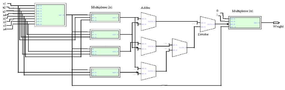
Figure 1. Block diagram of the Max-Min Calculator
Asica, Catania and Russo [12] assumed that each membership function is composed of nine segments. Based on this assumption, they used a binary search mechanism to obtain the matching degree between two membership functions. The main drawback of their fuzzy inference processor [13] is that they applied a detection process to extract active rules from the knowledge base. As a result, the inference speed of their fuzzy inference processor depends on the number of active rules. Therefore, their fuzzy inference processor is only suitable for applications that have few active rules.
In this paper, it is assumed that each membership function is in trapezoid-shape. The matching degree between two trapezoid-shaped membership functions can be obtained by providing fuzzy input to the controller. Based on this analysis, a pipelined parallel FPGA based hardware is proposed to take advantage of basic idea.
The rest of the paper is organized as follows. Section II present the motivation for fast calculation of the matching degree. The architecture of our proposed fuzzy inference processor is described in section III. Comparisons with other hardware architectures are presented in section IV. Finally, some concluding remarks are presented in section V.
-
II. Min-max unit
The block diagram of the max min calculation is shown in fig.1. This block is used to calculate the degree of membership function. For this design, assuming that the membership grades are discretized into 16 levels which is represented by l=4 bits and it has 64 elements at universal disclosure i.e. e=6 bits. Thus the degree of membership ranges from 0 to 1 is represented as 0000 to 1111, respectively.
The max-min block is used to calculate the matching degree of the fuzzy input and antecedent membership functions as shown in fig. 1. Assume that the trapezoidal antecedent membership function is (a1, a2, a3, and a4) and the trapezoidal fuzzified input is (x1, x2, x3, and x4). The following four mutually exclusive conditions are used to calculate the degree of matching between the antecedents and fuzzified input membership functions. The conditions are as follows:
-
1. If a 3 < x 2 and x 1 < a 4: MD is the grade value of the cross-over point ( Fig. 2).
-
2. If x3 < a2 and a1 < x4: MD is the grade value of the cross-over point (Fig. 3).
-
3. If a1=x1, a2=x2, a3=x3, a4=x4: MD = ‘1’ (Fig. 4).
-
4. If a 4 ≤ x 1 or x 4 ≤ a 1: MD = ‘0’ (Fig. 5).
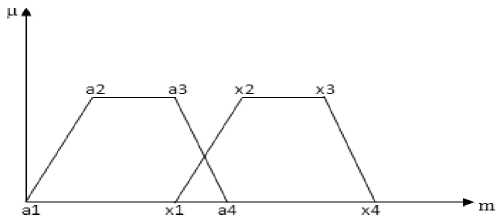
Figure 2. Cross Over Point
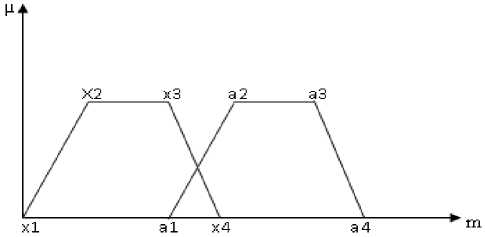
Figure 3. Cross Over Point
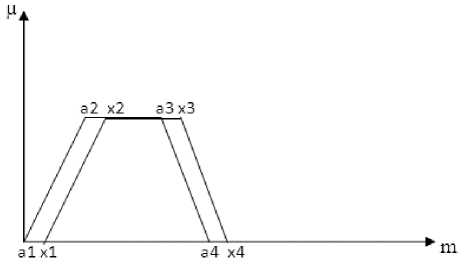
Figure 4. Complete Matching
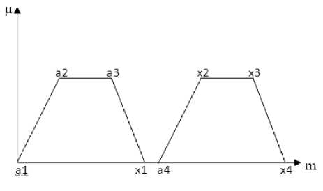
Figure 5. No Matching
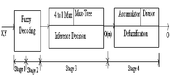
Figure 6. The Pipelined Architecture
The max-min calculator circuit is consisting of comparator, multiplexers, subtractors, adders, divider and shifter circuit. The comparator circuit is used to differentiate four condition to find matching degree. The inputs to the comparator circuit are a1, a2, a3, a4, x1, x2, x3 and x4, whereas circuit produces two bit output to find out matching degree for four different condition that may occur. According to the result obtained by the comparator circuit, the output of the dedicated max-min calculation hardware is selected. The 00 and 11 output value of comparator circuit indicates that the two membership functions are completely matched or mismatched respectively. The value “01” output of the comparator circuit realizes the equation (1) and “10” realizes equation (2).
If (a3 < x2 and x1 < a4) Then
. . (х2- а3)
M.D.=2 1 -2 1 (х2 - а3) + (а4-х1)
If (x3 < a2 and a1 < x4) Then
. . (а2-х3)
M.D.=21-2 ах
(а2 -х3) + (х4- а1)
The proposed fuzzy controller has pipelined parallel architecture with 16 and 8 rules, two inputs and one output variable. The membership degree is divided into 16 levels which is represented by l=4 bits.
-
III. PROPOSED ARCHITECTURE
The fuzzy inference execution can be split into the following three primary steps: fuzzy decoding , inference decision , and defuzzification . The proposed fuzzy decoding is a pipelined architecture is shown in fig. 6. The center of gravity (COG) technique is used for defuzzification process. This can be done using accumulation and division process.
-
A. Fuzzy Decoding
The function of fuzzy decoding unit is to find the weights of rules, including weight 0, weight 1… weight 16, as shown in fig.7. The function of the max-min calculator is split into two phases. Thus, the fuzzy decoding step is also divided into two pipeline stages.
Two max-min calculation units operate in parallel to obtain the matching degrees of the two input variables at the same time, as shown in Eqs. (3) and (4).
∝f= max(min(X(m), At (m)))(3)
∝? = max(min(Y(m), Bi (m)))(4)
Then, a minimum unit is employed to obtain the weight, as shown in equation (5).
weigℎt= (∝t,∝ в )(5)
Note that, at each pipeline stage, a rule will take only two clock cycles. Thus, in order to utilize the fuzzy decoder fully, four rules are processed sequentially during a pipeline stage. In the first pipeline stage, two 4-to-1 multiplexers are used to sequentially pass the rules to max-min calculators; in the second pipeline stage, a 1-to-4 demultiplexer is used to sequentially store the obtained weights. This fuzzy decoder is expandable. To process 16 rules, four fuzzy decoders, operating in parallel are employed. During a pipeline stage, rules R4i ( i = 0, 1, 2, 3) are processed in the first and the second cycles, rules R 4 i +1 ( i = 0, 1, 2, 3) are processed in the third and the fourth cycles, rules R 4 i +2 ( i = 0, 1, 2, 3) are processed in the fifth and the sixth cycles, and so on.
-
B. Inference Decision
The inference decision unit finds degree of membership of the output variable, including O (0), O (1), …, and O (15). Each grade O ( m ), where m = 0, 1, 2, …, and 15, is determined by means of a maximum of 16 control decisions, which are O 0( m ), O 1( m ), …, and O 16( m ).
Simultaneously operating, 16 control decision units are employed. As equation (6) shows, the control decision of a rule O i ( m ) is obtained by means of the minimum between weight i and C i ( m ), where m = 0, 1, 2, …, and 16, and i = 0, 1, 2, …, and 16.
Ot ( m ) = min(w ,C (m))
Fig. 8 depicts the control decision unit of a fuzzy rule. The weighti , which is the weight of rule Ri , is calculated in the fuzzy decoding step. Ci is the consequent membership function associated with rule Ri . For computation of Oi ( m ), where m = 0, 1, 2, _., and 16, we need to have all 64 elements of C . To find all the control decisions within a pipeline stage, four 4-to-1 multiplexers are used. Then, Ci (15), Ci (11), Ci (7), and Ci (3) are sampled on the first cycle, Ci (14), Ci (10), Ci (6), and Ci (2) are sampled on the second cycle, and so on. Consequently, Oi (15), Oi (11), Oi (7), and Oi (3) are obtained on the first cycle, Oi (14), Oi (10), Oi (6), and Oi (2) are obtained on the second cycle, and so on.
Four maximum units, i.e., MAX1, MAX2, MAX3, and MAX4, are used to calculate output. The output is calculated using equation (7) is as follows:
( ) = max( ( ),. . ., ( )) (7)
Each maximum unit has 64 inputs. In the first cycle, the inputs to MAX1 are (3), (3),… (3) ; the inputs to MAX2 are (7), (7),…. . (7), the inputs to MAX3 are O 0 (11), O 1 (11), ^, and O 15 (11); and the inputs to MAX4 are
(15), (15),… (15). In the second cycle, the inputs to MAX1 are (2), (2), (2)… (2); the inputs to MAX2 are
(6), (6), (6)… (6) ;the inputs to MAX3 are (10), (10), (10)… (10); the inputs to MAX4 are (14), (14), (14)… (14) ; and so on.
аД47:0] ------
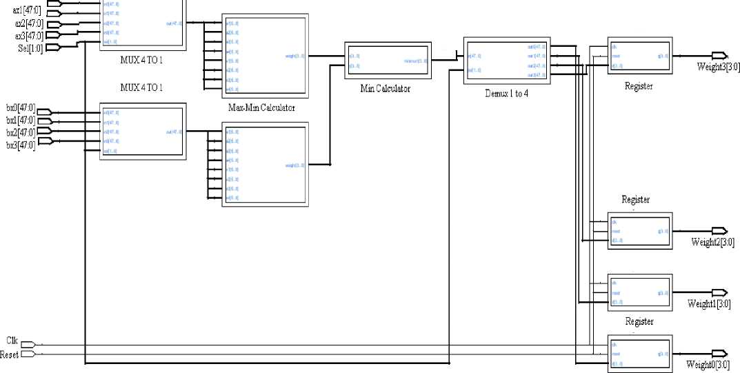
Figure7. Fuzzy decoder unit
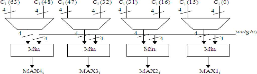
Figure 8. Fuzzy control decision unit
C. Defuzzification
TABLE I COMPARATIVE STUDY OF DIFFERENT FUZZY CONTROLLER
|
Implementation |
Proposed |
Shabiul Islam et al. 2008 [14] |
S.H. Huang et al. 2005 [3] |
Frias et al . 2001 [10] |
R.D’Am ore et al .2001 [8] |
Homburg et al .2003 [5] |
V. Salapura 2000 [13] |
|||
|
CycloneII-EP2C70F896 C8 |
APEX 20K 200 EF484 |
Dedicated ASIC Design |
DSP Proc essor TSM 320 C62 01 |
FPGA ALTER A Flex10k |
FPGA XilinxXC2 v1000 |
Extra Instructions for MIPS Processor |
||||
|
Resolution |
l=4 e=6 |
- |
l=4 e=6 |
l=6 e=8 |
- |
l=5 e=8 |
l=6 e=8 |
l=6 e=8 |
- |
|
|
Active Rules |
8 |
16 |
9 |
64 |
64 |
9 |
4 |
7 |
49 |
9 |
|
Inputs |
2 |
2 |
2 |
2 |
8 |
2 |
2 |
6 |
6 |
2 |
|
Outputs |
1 |
2 |
1 |
1 |
4 |
1 |
1 |
1 |
1 |
1 |
|
MFLIPS |
34.41 |
0.81 |
5.42 |
7 |
4 |
4.5 |
0.615 |
3.5 |
0.5 |
0.568 |
The Center of gravity defuzzification method is used to find the final output. It includes two pipeline stages: accumulation and division. For processing the output, four parallel maximum units are used. The numerator N and denominator D is calculated using equation (8) and (9), respectively.
N = E ™”3 m * О(m) + E ™”7 m * 0(m) +
E ™” 1 1 m * O ' (m) + E l” 1 5 m * O'(m) (8)
m=3
m=7
D = ^O(m) + ^O(m)
m = ll m=15
+ ^ 0(m) + ^ 0(m)
8 12
After calculating the value of N and D, the output will be calculated using N/D.
-
IV. COMPARISON
Some high-speed fuzzy inference processors are proposed in [3, 5, 8, 10, 13] and [14] using different approaches such as ASIC, FPGA, DSP and MIPS processor approach.
Note that the [10] is a software implementation running on a high-speed DSP, those in [5, 8] and [14] are
FPGA implementations, and [13] is an extension of the MIPS processor. Table I shows the comparative study of proposed design with different architectures in terms of resolution , number of inputs and outputs, number of rules and speed in terms mega logic inferences (MFLIPS). Table I compares proposed fuzzy inference processor with above mentioned fuzzy inference processor concludes that it achieves very high performance. It is worth mentioning that [3] and [13] executed their instructions sequentially. Therefore, the works in [3] and [13] are only suitable for applications that have few rules or whose required inference speeds are not high.
-
V. CONCLUSION
In this paper, a high-speed VLSI fuzzy inference processor for the real-time applications using trapezoidshaped membership functions has been presented. From the analysis it is clear that the matching degree between two trapezoid-shaped membership functions can be obtained without traversing all the elements in the universal disclosure set of all possible conditions. A pipelined parallel VLSI architecture has been proposed to take advantage of this basic idea.
The proposed fuzzy inference processor has been implemented on FPGA CycloneII- EP2C70F896C8. The proposed controller is designed and found maximum clock rate as 12.96 MHz and 275.33 MHz for 16 and 8 rules respectively. Thus, the inference speed is 0.81 and 34.41 MFLIPS for 16 and 8 rules respectively.
References FPGA Based Pipelined Parallel Architecture for Fuzzy Logic Controller
- K. Nakamura, N. Sakashita, Y. Nitta, K. Shimomura, and T. Tokuda, “Fuzzy inference and fuzzy inferenceprocessor,” IEEE Micro, Vol. 13, 1993, pp. 37-48.
- M. Togai and H. Watanabe, “Expert system on a chip: an engine for real-time approximate reasoning ,” IEEE Expert Magazine, Vol. 1, 1986, pp. 55-62.
- S.H.Huang et al, “High Speed Fuzzy Inference processor Using Active Rules Identification” JCIS 06-Joint conference on Information Sciences, Oct 8-11, 2006, Taiwan.R. J. Dirkman and J. Leonard,68HC11 Microcontroller Laboratory Workbook, Prentice Hall, 1996.
- J.Y. Lai et al, “A High Speed VLSI Fuzzy Logic Controller with Pipeline Architecture”, Proceedings of IEEE International Conference on Fuzzy Systems, vol. 3, pp.1054-1057, 2001
- F. Homburg and R. Palomera-Garcia, “A high-speed scalable and reconfigurable fuzzy controller,” in proceedings of IEEE International Symposium on Circuits and Systems, Vol. 5, 2003, pp. 797-800
- H. Peyravi, A. Khoei, and K. Hadidi, “Design of an analog CMOS fuzzy logic controller chip”, Fuzzy Sets and Systems 132, PP. 254-260, 2002.
- J. M. Jou and P. Y. Chen, “An adaptive fuzzy logic controller: its VLSI architecture and applications,” IEEE Transactions on Very Large Scale Integration (VLSI) Systems, Vol. 8, 2000, pp. 52-60.
- R. D’Amore, O. Saotome, and K. H. Kienitz, “A two-input, one-output bit-scalable architecture for fuzzy processors,” IEEE Design and Test of Computers, 2001, pp.56-64.
- N. E. Evmorfopoulos, and J. N. Avaritsiots, “An adaptive digital fuzzy architecture for application- specific integrated circuits”, Active and Passive Elec. Comp., Vol. 25, pp. 289-306, 2002.
- E. Frias-Martinez, “Real-time fuzzy processor on a DSP,” in Proceedings of IEEE International Conference on Emerging Technologies and Factory Automation, Vol.1, 2001, pp. 403-408.
- Sajad A. Loan and Asim M. Murshid, “A Novel Fuzzy Inference Processor using Trapezoidal-Shaped Membership Function” Proceedings of the IEEE International Conference on Open Systems (ICOS2011), September 25 - 28, 2011, Langkawi, Malaysia.
- G. Asica, V. Catania, M. Russo, and L. Vita, “Rule driven VLSI fuzzy processor,” IEEE Micro, Vol. 1996, pp. 62-74.
- V. Salapura, “A fuzzy RISC processor” , IEEE Transactions on Fuzzy Systems, Vol.8, 2000, pp. 781-790.
- Shabiul Islam, Mukter Zaman, Bakri Madon, and Masuri Othman (2008). Designing Fuzzy Based Mobile Robot Controller using VHDL. International Journal of Mathematical Models and Methods in Applied Science, Issue 1, Volume 2, ,p-p 138-142.
