Free Space Optical Channel Characterization and Modeling with Focus on Algeria Weather Conditions

Author: Mehdi ROUISSAT, A. Riad BORSALI, Mohammad E. CHIKH-BLED
Journal: International Journal of Computer Network and Information Security(IJCNIS) @ijcnis
Article in issue: 3 vol.4, 2012.
Free access
Free-Space Optics (FSO) is a wireless optical technology that enables optical transmission of data, voice and video communications through the air, up to 10 Gbps of data, based on the use of the free space (the atmosphere) as transmission medium and low power lasers as light sources. Quality and performance of FSO links are generally affected by link distance and weather conditions like environmental temperature and light, sun, fog, snow, smoke, haze and rain. In this paper we study the effects of weather conditions on the performance of FSO links, taking the climate of Algeria as an example, and since there is no known analysis on the effects of weather conditions in this country, this paper offers an attempt to analyze and identify the challenges related to the deployment of FSO links under Algeria's weather. We also present a Graphic User Interface "GUI" to provide an approximate availability estimate of an atmospheric optical link in term of probability of connection.
Algeria, Atmospheric Attenuation, Availability, Free Space Optic, Performance
Short address: https://sciup.org/15011064
IDR: 15011064
Text of the scientific article Free Space Optical Channel Characterization and Modeling with Focus on Algeria Weather Conditions
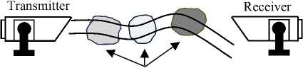
Free Space Optics (FSO) or optical wireless communications (WOC) refers to a transmission of modulated infrared beams through the atmosphere, over distances up to several kilometers (Figure. 1). The transmission theory of FSO is essentially the same as that for fiber optic, the principal difference is that the energy beam is collimated and sent through the atmosphere from the source to the destination, rather than guided through an optical fiber.
Compared to the radio frequency, FSO systems have many advantages, such as larger bandwidth, better privacy, smaller antenna components size, and lower components costs. Despite these advantages, FSO systems also faces serious challenges fixed or time varying, such as weather conditions; geometric attenuation, physical obstructions, solar interference and building sway.
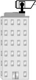
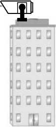
Figure1: FSO transmitter and receiver mounted on top of two buildings in point to point connection
In Optical Fiber systems, the fiber, connectors, slicers, and so on cause these losses. The receiver typically has a specific minimum sensitivity at a given data rate, and the task is to make sure that the launch power minus the loss factor stays above the minimum sensitivity to guarantee reliable operation of the system [1]. This procedure is similar for FSO systems.
However, an important difference between fiber-based and FSO communication systems is related to the fact that the loss of the media ( air ) between the transmitter and the receiver can vary in time due to the impact of weather. Therefore, it is important for FSO systems to take weather conditions into consideration.
One of the key methods to determine how well a Free Space Optical link will perform is to calculate the link margin, which gives an approximate value for the amount of environmental and atmospheric loss the FSO system will be able to tolerate, and if it is able to deliver sufficient optical power to the opposite end of the link in worst communication conditions.
The reminder of this paper is organized as follows; in section 2 we present how to calculate the link margin of a wireless optical link, section 3 present the different atmospheric challenges that can interrupt the FSO link and the link margin should tolerate, section 4 presents a model of the FSO atmospheric channel and description of a GUI used for the availability prediction, this is followed by a conclusion in section 5.
-
II. link margin
The optical link margin is the extra power available above the sensitivity of the receiver, defined by [2]:
M liaison (dB) = P e + |S r | ــ Att Geo (dB) ــ Att mol (dB) ــ ∑ P sys (dB) (1)
Where:
-
- P e is the amount of optical energy transmitted (dBm);
-
- S r is the sensitivity of the receiver (dBm);
-
- AttGeo is the link geometrical attenuation (dB);
-
- Att mol is the link molecular attenuation (dB);
-
- Psys (dB) are the system losses.
The link margin determines if the system is able to deliver sufficient optical power in worst atmospheric conditions (Fog, rain, snow, reduced visibility due to smoke, scintillation etc.) by considering the characteristics of the Free Space Optical communication system and the environment where the link is to be deployed.
To make the link more reliable, we would want to leave a larger link margin than the minimum nominal received power level. However, allocating signal power to the link margin means taking away power that would otherwise go to increasing the distance at which we could separate the transmitter and receiver. This simple logic shows a trade-off between distance and reliability [1].
A. Geometric losses
Geometric losses are those losses that occur due to the spreading of the transmitted beam between the transmitter and the receiver [3]. Typically, the beam spreads to a size larger than the receive aperture, and this “overfill” energy is lost. Geometric losses can be approximated by the following formula:
Captur
dB
Where:
Strans and Scaptur are the diameters of the active area in the transmitter and the receiver respectively (mm), θ is the divergence angle ( mrad ) and l is the link distance ( m ).
The geometric path loss for an FSO link depends on the beam-width of the optical transmitter ( θ ) (figure. 2), the path length ( l ), and the divergence angle. Transmitter and receiver aperture diameters are quantifiable parameters, and are usually specified by manufacturer.
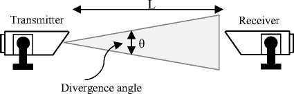
Figure 2. The divergence angle between two FSO units
The beam spreads to a size larger than the receiver’s aperture; most of the energy is lost. By increasing receiver’s aperture area, more light could be collected by the telescope, and geometric loss would reduce. The geometric path loss is present for all FSO links, and must always be taken into consideration in the planning of any link.
B. Molecular attenuation
Molecular attenuation results from the effect of absorption and diffusion of the infrared light by gas molecules present in the terrestrial atmosphere, causing attenuation to the beam, and directly affecting the transmission distance and the availability of the link.
The most common absorbing particles are water, carbon dioxide, and ozone, which make the molecular absorption a selective phenomenon.
Table 1. Molecular absorption at some typical wavelengths
|
Wavelength (nm) |
Specific Molecular Absorption (dB/km) |
|
550 |
0.13 |
|
690 |
0.01 |
|
850 |
0.41 |
|
1550 |
0.01 |
The selective phenomenon results in a spectral transmission of the atmosphere presenting transparent zones, called atmospheric transmission windows, and opaque zones, called atmospheric blocking windows. Some typical values of molecular absorption coefficients for several laser wavelengths are given in Table.1, calculated for a clear atmosphere.
C. The system losses
The first source of loss in a free-space optical system is due to imperfect lenses and other optical elements (such as couplers). For example, a lens might transmit 96% of the light, but 4% gets reflected or absorbed. The amount of this loss depends on the characteristics of the equipment and quality of the lenses. This value needs to be measured or derived from the manufacturer of the optical components.
-
III. Atmospheric channel losses
Atmospheric attenuation is present when the signal encounters air molecules and other particles (solid or liquid) suspended in the air (aerosols). The performance of FSO Link is subject to several atmospheric factors like environmental temperature, fog, smoke, haze and rain, but it is typically dominated by fog.
A. Fog’s attenuation
The major challenge to FSO communications is fog, since the size of the fog’s particles is comparable to the optical wavelengths that are normally used for FSO transmission [4]. It can modify light characteristics or completely hinder the passage of light through a combination of absorption, scattering and reflection. It was observed that for dense maritime fog the specific attenuation can be up to 480 dB/km [5]. In the case of moderate continental fog, the specific attenuation can reach 130 dB/km [6].
According to data obtained from the “ National Office of Meteorology of Algeria” [7], fog’s appearance depends on the location (longitude and latitude) and on the season. Table. 2 shows the number of days where fog appear for a give year in four main cities in Algeria (Fig. 3), three of them are in the north (Algiers, Annaba and Oran) and the last one in the south (Gardaya).
Table 2. Fog’s appearance some cities of Algeria
|
Algiers |
Annaba |
Oran |
Gardaya |
|
|
Jan |
5 |
0 |
5 |
0 |
|
Feb |
6 |
5 |
6 |
0 |
|
Mar |
2 |
5 |
2 |
0 |
|
Apr |
0 |
0 |
0 |
0 |
|
May |
4 |
0 |
2 |
0 |
|
Jun |
1 |
2 |
0 |
0 |
|
Jul |
4 |
3 |
0 |
0 |
|
Aug |
2 |
1 |
0 |
0 |
|
Sep |
0 |
0 |
2 |
0 |
|
Oct |
3 |
2 |
3 |
0 |
|
Nov |
10 |
0 |
13 |
0 |
|
Dec |
5 |
1 |
1 |
0 |
|
Year |
42 |
19 |
34 |
0 |
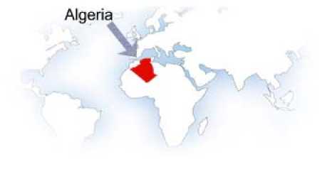
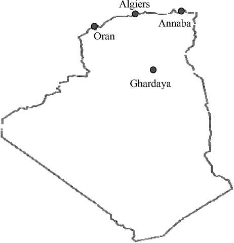
Figure 3. Algeria’s Map
Al Naboulsi et al. (France Telecom model) have provided relations to predict fog attenuation by characterizing advection and radiation fog separately [8].
-
• Advection fog is formed by the movement of wet and warm air masses above colder maritime or terrestrial surfaces. It is characterized by liquid water content higher than 0.20 g/m3 and a particle diameter close to 20 µm [9]. Al Naboulsi provides the advection fog attenuation coefficients as
... 0.11478 2 + 3.8367
^ adv ( 2 ) =------------------- (3)
v
-
• Radiation fog is related to the ground cooling by radiation. It appears when the air is sufficiently cool and becomes saturated. This fog generally appears during the night and at the end of the day. Particle diameter is around 4 µm and the liquid water content varies
0.18126
2
2
+
0.13709
2
+
3.7502
between 0.01 and 0.1 g/m3. Al Naboulsi provides the radiation fog attenuation coefficients as:
CT rad ( 2 ) =----------------------------------- (4)
v
The specific attenuation in dB/km for both types of fog is given by Al Naboulsi as follows a ec (dB / km) = 10— ct(2) (5)
spec ln(10)
Knowing the link margin, we can deduce, by dichotomy, the interruption probability of the link due to fog.
B. Rain’s attenuation
Unlike fog, rains has a little effect on FSO and is not a major factor on FSO availability, but heavy rains may cause an important attenuation for the optical signal and attenuate the strength of the transmitted beam along the path.
Rainfall in Algeria decrease from East to West and from North to South, as we can see on Table. 3, we have 613 mm yearly’s rain factor in Annaba City (the east), 370.3 mm in Oran (the west), 686.6 mm in Algiers (the north part) and 61.8 mm yearly in Ghardaya (the south part).
Rains appear in Algeria over the year, and it generally takes peak during November December and January, for all the parts of the country.
Table 3. Rain quantity in the four cities of Algeria
|
Algiers |
Annaba |
Oran |
Gardaya |
|
|
Year |
686.6 mm |
613.0mm |
370.3 mm |
61.8 mm |
Attenuation due to rain, independent of the wavelength, is a function of the precipitation intensity R (mm/h) according to [10].
Aff rain = 1, 076 * R 0,67 dB/km (6)
Knowing the link margin, we can deduce, by dichotomy, the interruption probability of the link due to rain.
C. Snow’s attenuation
Snow like rain has a little effect on FSO link; this effect could increase in heavy snow. Snow generally falls in the form of flaks, or in certain very cold countries in form of ice crystal aggregates, the flaks can reach 15 millimeters [11]. The snow’s flacks are generally larger than rain’s drops and cause more fluctuations and significant snow’s attenuation and may causes link’s failure of narrow laser’s beam when the snow’s flakes are larger. The received signal level depends on the diameter of the snowflakes and distance from the transmitter.
Attenuation due to snow is a function of the wavelength (λ nm ) and precipitation intensity S (mm/h) according to the following relations:
-
• Wet snow (altitude <500m):
Aff snow = (0, 0001023λ + 3, 7855476) × S0,72 dB/km (7)
-
• Dry snow (altitude > or = 500 m)
Aff snow = (0, 0000542λ + 5, 4948776) × S1,38 dB/km (8)
Snow intensity S is the fundamental parameter used to locally describe the snow. Knowing the link margin deduced from the optical power link budget, we can deduce, by dichotomy, the interruption probability of the link due to snow.
In Algeria snow appear in the north of the country (Algiers, Annaba and Oran), generally one or two time by year; however, in the south (Gardaya) the snow never appear. According to this statistic, the snow is not a problem for FSO links deployment in Algeria.
D. Scintillation’s Losses
The Performance of many optical wireless communication systems is affected by the scintillation on bright sunny days. Scintillation or “hot air” is one of the effects of the temperature differentials changes of the air particle density.
Cells with differen t refractive index
Figure 4. FSO link with turbulent cells
V. Conclusion
Cells or hot pockets (figure. 4), of air with variable size (10 cm – 1 km), with variant refractive index are created along the transmitting path, that moves randomly in space and time, changing the refractive index of the air media, which led to scattering, multiple paths and arrival angle variations at the receiver side, which can affect directly the link quality and availability.
Scintillation is most significantly at midday or midnight due to the highest temperature difference between the earth’s surface and the atmosphere. A parameter is often used as a measure of the scintillation strength is the atmospheric structure parameter or Cn 2 .
Aff scintillation = 2^23.17* k7,6 * C 2 * L Ш6 (9)
Where: k (m–1) is the wave number 2π/λ
Cn2 is for low turbulence 10 -16 , for moderate turbulence 10 -14 , for high turbulence 10 -13 [9].
Scintillation contributes major challenge for FSO communications links, especially in the southern part of Algeria where the temperature is higher, almost for all over the year, and it can add some attenuation in the summer for the north part of the country.
-
IV. Availability prediction
The design of wireless networks offers challenges not present in fixed networks, FSO availability for instance depends on a variety of factors, including equipment reliability and network design, but these are well known and fairly quantifiable, the biggest unknown challenge is the effect of atmospheric attenuation. A key issue in the deployment of Free Space Optical (FSO) communications networks is the availability prediction. In this section we present a graphic user interface (GUI) (Figure. 5) that allows evaluating the availability of an atmospheric optical communications link in term of availability.
Attenuation due to scintillation is given by: The GUI output data are:
Geometric losses;
-
• Atmospheric losses;
-
• Beam Spot;
-
• Link Margin and Linear Link Margin;
-
• Extra Power.
This availability prediction tool may be a useful and viable addition in the simulation and modeling field for all specialists in that field who implement high speed Free Space Optical communications networks in their own purposes or for their clients.
In this paper we analyzed the different challenges on the design and performance of a terrestrial FSO link and the effects of weather condition on the links availability taking the weather of Algeria as example of study, where the main limiting factors for FSO links design are: scintillation, fog and heavy rains. Scintillation presents a challenge in the Southern parts
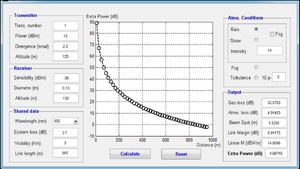
Figure 5. Graphic user interface for availability prediction
of the country where the temperature is higher almost all the year. Fog and heavy rain presents a challenge in the north of the country.
We have introduced also a developed GUI which allows evaluating the quality of service and providing an approximate availability estimate of an atmospheric optical link in term of probability of connection. it starts from the data of equipments and climatic and atmospheric parameter (Fog, snow, rain, etc) to give the link margin, interruption probabilities for each type of attenuation (aerosols, scintillation, ambient solar light, rain, snow, etc) and the available extra power. It may be a good tool to the study and the technical choice of FSO infrastructures and the appropriate optic wavelength for point-to-point very high speed links on ground-ground short distances.
-
[2] .
-
[3] .
-
VI. REFERENCES
-
[1] . Heinz Willebrand and Baksheesh S. Ghuman. Free Space Optics: Enabling Optical Connectivity in Today’s Networks. Sams Publishing, Indianan USA.2002.
Mourad Chabane, Maher C. Al Naboulsi, Herve Sizun and M. O. Bouchet. A new quality of service FSO software. Proc. SPIE 5465, 180 (2004).
-
S. Bloom, E. Kovevaar, J. Schuster and H.Willebrand. Understanding the Performance of Free-Space Optics. Journal of Optical Networking, pp.178-200, Vol. 2, No. 6, June 2003.
M.S.A Wan, E. Leitgeb, F. Nadeem, M.S Khan, C. Capsoni. A new Method of Predicting Continental Fog Attenuations for Terrestrial Optical Wireless Link. IEEE computer Society 2009.
M. Gebhart and Al, Measurement of light attenuation in dense fog conditions for optical wirelesses links. Proceedings of SPIE, vol. 581. 2005.
B. Flecker and al. Results of measurements for optical wirelesses channel under dense fog conditions regarding different wavelength.
Proceeding of SPIE vol. pp, 6303-63033, 2006.
Al Naboulsi M, Sizun H, et de Fornel F, Fog attenuation prediction for optical and infrared waves, Opt. Eng 43 no. 2, 319-329. 2004.
BOUCHET. Free-Space Optics – Propagation and Communication. Hermes Science Publishing, 2006. M. Akiba, K. Walkmori, K. Kodate, S. Ito. Measurement and simulation of the effect of snow fall on free space optical propagation. Applied Optics Vol.47 No. 31, PP 5736-5742 (2008).
References Free Space Optical Channel Characterization and Modeling with Focus on Algeria Weather Conditions
- Heinz Willebrand and Baksheesh S. Ghuman. Free Space Optics: Enabling Optical Connectivity in Today's Networks. Sams Publishing, Indianan USA.2002.
- Mourad Chabane, Maher C. Al Naboulsi, Herve Sizun and M. O. Bouchet. A new quality of service FSO software. Proc. SPIE 5465, 180 (2004).
- S. Bloom, E. Kovevaar, J. Schuster and H.Willebrand. Understanding the Performance of Free-Space Optics. Journal of Optical Networking, pp.178-200, Vol. 2, No. 6, June 2003.
- M.S.A Wan, E. Leitgeb, F. Nadeem, M.S Khan, C. Capsoni. A new Method of Predicting Continental Fog Attenuations for Terrestrial Optical Wireless Link. IEEE computer Society 2009.
- M. Gebhart and Al, Measurement of light attenuation in dense fog conditions for optical wirelesses links. Proceedings of SPIE, vol. 581. 2005.
- B. Flecker and al. Results of measurements for optical wirelesses channel under dense fog conditions regarding different wavelength. Proceeding of SPIE vol. pp, 6303-63033, 2006.
- http://www.meteo.dz/
- Al Naboulsi M, Sizun H, et de Fornel F, Fog attenuation prediction for optical and infrared waves, Opt. Eng 43 no. 2, 319-329. 2004.
- BOUCHET. Free-Space Optics – Propagation and Communication. Hermes Science Publishing, 2006.
- M. Akiba, K. Walkmori, K. Kodate, S. Ito. Measurement and simulation of the effect of snow fall on free space optical propagation. Applied Optics Vol.47 No. 31, PP 5736-5742 (2008).
- Rec. ITU-R P.1814. Prediction methods required for the design of terrestrial free-space optical links. ITU, Geneva, Switzerland, Sept. 2008.
