Geo satellite attitude and orbit control: fixed orbit control thrasters

Author: Ermoshkin Yu. M., Raevsky V.A., Urusov V.M.
Journal: Сибирский аэрокосмический журнал @vestnik-sibsau
Section: Авиационная и ракетно-космическая техника
Article in issue: 5 (26), 2009.
Free access
The paper describes the enhanced application ofhigh-economical electro-jet orbit control thrusters for geostationary satellites; in particular, generation of controlling moments to the benefit of satellite attitude determination and control subsystems in the course of orbit control maneuvers ongoing. The scheme with thrusters fixed on a satellite body is analyzed. Possible orbit control session procedures are proposed on the basis of controlling moments generation. Advantages and disadvantages of the proposed approach are analyzed.
Spacecraft, propulsion subsystem, orbital control, attitude control, thruster allocation
Short address: https://sciup.org/148176107
IDR: 148176107
Text of the scientific article Geo satellite attitude and orbit control: fixed orbit control thrasters
The performance of thruster subsystems dramatically – attitude control (creation of controlling moments)
influence the geostationary satellite platform characteristics. The mass of thruster units filled can achieve 15...20 % of a satellite mass, the power consumption of electro-jet thruster unit can be up to 4 kW; therefore even minor reduction of the thruster unit mass and the power consumption allows reducing satellite mass and increasing payload capacity. Taking this information into account, we believe it to be important and reasonable to consider issues of optimal development of satellite attitude and orbit control maneuvers using thruster subsystems. Such aspects usually become essential at the initial design stage of a new satellite design. In practice, solutions are mainly subjective, so their detailed examination and formalization is desirable.
There are three known concepts of attitude and orbit control arrangements using thruster units:
-
– individual thruster units to ensure attitude and orbit control;
ensured by orbit control thrusters fixed on a satellite body;
-
– attitude control ensured by orbit control thrusters mounted on one- or two-step drives.
Each of these approaches has its advantages and disadvantages. The first approach is a traditional and simple one implemented on a lot of satellites, including satellites developed and manufactured by JSC ISS (former NPO-PM) [1]. This approach allows to individually and independently solve the ballistic task of controlling a SC center of gravity position (orbit control task) and a SC angular position (attitude control task).
The second approach promises a certain mass saving due to refusal of separate attitude control thruster unit, though it probably requires more complicated orbit correction maneuver procedures as the orbit correction task shall be accompanied with a task of controlling moments generation to allow ADCS wheel unloading. Such an approach is employed for YAMAL-100 satellite [2]. It is worth mentioning that a minor supplemented attitude control thruster unit is still required, which will assist in generating controlling moments in the SC acquisition modes (after a booster separation) and in the safe-hold modes, in other words, in the situations when plasma thrusters shall not be fired due to intensive power balance.
The third approach is a modification of the second one. Possibilities of attitude control and redundancy are enhanced toa certain extent due to drives used; however, some mass increase is caused by additional mechanical and electronic units installed. Additional needs in thruster position orientation occur; structural strength, thermal modes, reliability and other aspects shall be analyzed and improved. Drive-based orbit control thrusters are mainly installed on foreign satellites [3].
We would like to note that according to any of the three approaches the main reliability requirement shall be met, in particular, a failure of a single item (a thruster, in our case) shall not cause the impossibility to solve a task, that is, impossibility to generate thrust in any of required four directions (North-South, West-East) and controlling moments along any of three axes.
Comparative analysis of various thruster subsystem designs can be performed in terms of the criterion of total filled masses of thruster units (or masses of variable components in comparison with the selected baseline design). It is also obvious that such analysis can be only possible for a certain satellite layout (a typical layout, for example).
Let us choose a scheme in figure 1 as a typical one, that is, individual attitude control and thruster units and orbit control thruster units. Consider the possibility to arrange attitude control and orbit control maneuvers taking into account the reliability requirements in the scheme with orbit control thrusters fixed. The efficiency of the scheme under investigation will be characterized by the difference between the filled thruster unit mass and the typical scheme.
Let a 2-m edge cube be a typical configuration of an unsealed satellite body (fig. 1). Satellites of the YAMAL family (RSC Energia) and satellites of the EXPRESS-1000 family (JSC ISS) are close to such configuration. On the North and South faces (axis Z ) solar arrays are installed, the rotation axis of which runs through the SC Center of gravity or close to it. On the West and East faces (axis Y ), as a rule, repeater antennas are installed (they are not shown in figure 1). That is why the location of orbit control thrusters on the diagonals of a square formed by cutting a satellite body with the plane YOZ is a justified solution. In particular, this solution is discussed in the paper [4]. It ensures the minimal impact of thruster jets impinging upon panels and antennas. Of course, other schemes are also possible, for example, the schemes with thrusters located outside the plane YOZ , however they are not the subject of this paper. Let’s accept the most widely used Russian plasma thruster M-100 (Experimental Design Bureau “Fakel”) as an orbit control thruster for the scheme considered.
Let us first consider the peculiarities of the baseline scheme. According to this scheme (fig. 1), the orbit control thruster lines of action nominally run through the SC center of mass. It is reasonable to perform the inclination correction by firing a pair of thrusters in direction +Z or –Z, the correction of longitude and eccentricity – by firing a pair of thrusters in direction +Y or –Y. With that, each thruster can contribute in generating thrust pulse along both Z axis and Y axis, depending on a pair of thrusters fired to which it belongs.
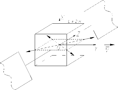
Fig. 1. Baseline orbit control thrusters: coordinate scheme and nominal thrust directions
The issue of a number of orbit control thrusters shall be considered separately. It goes without saying, that the minimal number of such thrusters is 4. Let us check whether the main reliability requirement is met in this case.
In case of failure of one of the pair of +Z thrusters, the inclination correction is performed by the pair of – Z thrusters. The same situation occurs under the failure of one of the pair of – Z thrusters.
The inclination correction can be performed using only one thruster (for example, + Z ), however, in this case to compensate a pulse in the Y direction (due to availability of a thrust component along the Y axis) it is necessary in 12 hours, during the inclination correction, to fire a thruster having a component of the opposite sign along the Y axis (in this case: – Z ).
Incaseoffailureofoneofthepairof + Y (– Y ) thrusters, the longitude correction is possible using the remaining healthy thruster. Then the pulse component in the Z direction will be reasonably used while selecting an appropriate time to fire thrusters within 24 hours.
Thus, actually 4 thrusters installed on the diagonals on the body edges within the plane YOZ ensure the orbit correction tasks in 4 directions with the main reliability requirement met. The failure of any thruster does not cause the impossibility to perform corrections in longitude and inclination.
However, we note that according to the scheme considered, under the simultaneous failure of two thrusters in the Y direction the longitude correction is impossible as the thrust generation in both + Y and – Y direction is required. The inclination correction (in the Z direction) using the remaining healthy thruster of the direction considered is also impossible in this case as there is nothing to compensate a thrust longitudinal component, which is a necessary element of the inclination correction maneuvers.
Taking all this information into account, at the design stage the decision most likely to be made is to install 8 orbit control thrusters (two thrusters along each diagonal). This decision is excessive in terms of reliability, because in this case longitude and inclination corrections will be possible even in case of failure of two thrusters. But due to the fact that the failures can occur not simultaneously, they can be considered as two single failures caused by resource problems. So, for the baseline design let’s assume to have 8 thrusters located pairwise, approximately in each diagonal direction within the plane YOZ.
When using orbit control thrusters fixed on a satellite body to generate controlling moments, it is obvious that the action line of each thruster thrust shall not run through the SC center of gravity but shall have a certain lever. As the controlling moments are necessary in some situations only, it shall be possible to generate thrust without moments when performing correction maneuvers. That is why the correction maneuvers shall be carried out using pairs of thrusters generating opposite moments. When it is not necessary to generate controlling moments, the thruster firing durations during the maneuvers shall be the same (provided the moments generated are equal). When it is necessary to generate controlling moments, the firing duration of thrusters of the pair considered shall not be the same. The moment pulse value is determined by the differences in thruster firing durations. Having in mind the necessity of pairwise thruster operation and satisfaction of the main reliability requirement, the total amount of orbit control thrusters for the scheme under consideration shall be at least eight. On the analogy of the baseline variant the thrusters (T1-T8) can be arranged in the diagonal directions within the plane YOZ (fig. 2), and the levers can be created by minor (for example first-order) deviations of thrusters within the corresponding planes (fig 3)
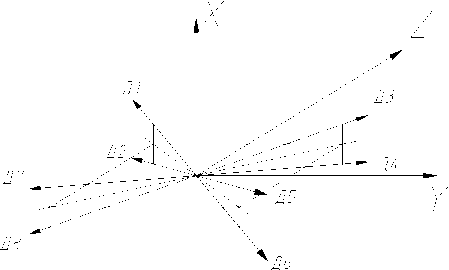
Fig. 2. Initial locations of orbit control thrusters according to the scheme with stable fixation of thrusters on a satellite body
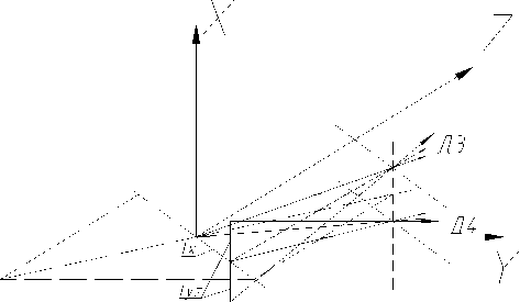
Fig. 3. Deviations of action lines of fixed thruster thrusts aimed at generating controlling moments (shown for T3, T4 only)
Under deviation by angle a = 1°, changes of thrust projection on the axes Y, Z can be neglected. With the thruster fired, the controlling moment is as shown below, for the chosen inputs of a satellite body geometrical configuration:
M = F • L • tga = 8 - 141.4 • 0.01745 = 19.74 » 20 g-cm.
When two thrusters generating the moments of the same sign are fired, the moment value is doubled. The sufficiency of 20 g∙cm controlling moment can be estimated by comparing this value with the disturbing moments caused by orbit control thrusters fired. However, to compute the disturbing moments a satellite configuration shall be specified with sufficient details. It is difficult to do it in this paper as we consider a theoretical satellite. We know the disturbing moments computed for satellites of the EXPRESS-1000 platform: max disturbing moment was (along the Y axis) 14 g∙cm, with average value of approximately 8 g∙cm. In this case, the controlling moment of approximately 20 g∙cm (based on the chosen inputs) is sufficient to ensure the control of SC angular position. It is also obvious that, in general, the excess of controlling moment over the disturbing moment can be provided by correct selection of deviation angle of the line of thrust action with respect to the COG direction.
With regard to the scheme investigated, let us consider the possibility of arranging the orbit correction maneuvers with simultaneous generation of controlling moments and satisfaction of the main reliability requirement.
In general, the task is solved by arranging the thrusters so that they could generate the correction pulses in the N–S and W–E directions (± Z , ± Y ) with and without controlling moments of both signs generated along three axes. We would like to note that the requirement of generating controlling moments along three axes is a little excessive. To control a GEO satellite angular position, it is necessary to generate controlling moments along the Z axis (pitch), and the controlling moments along the X , Y axes (yaw, roll) can be redistributed by wheel-based control system (taking into account SC orbital motion). In other words, it is enough to generate only controlling moments along the roll and pitch axes. However, in this paper we are interested in solving the general task of generating controlling moments along three axes. It is obvious that if there is a general solution then a simpler specific solution can always be found. Taking into account the condition of limited power consumption, we assume that not more than two thrusters can be fired at a time.
The initial scheme of orbit control thruster locations is assumed as a baseline (figure 2). It can be modified to generate controlling moments as shown in figures 3, 4, 5. According to the initial scheme, the thrusters are located on the body edges, the principle thrust generation directions are along the square edges formed by cutting a satellite body with the plane YOZ . In each direction two thrusters are installed close to each other. The thrusters are 8 in total. On the basis of overall dimensions of a thruster unit and the possibility of its installation on the satellite body, each thruster is installed so that its axis nominally runs through the center of gravity at a certain angle to the plane YOZ . Let us assume that the axes of thrusters T1, T3, T5, T7 are turned to the direction + , andT2, T4, T6, T8areturned to the direction – X , symmetrically (figure 2).
To generate controlling moments along the axis (yaw), pairsofthrustersT1+T2, T3+T4, T5+T6, T7+T8shallbe rotated by a small angle, for example by 1 , along the axes coinciding with the edges as assumed above. For the purpose ofsymmetry, pairsT1+T2, T3+T4canberotatedtothe +Z direction, pairs T5 + T6, T7 + T8 –tothe –Z direction (fig. 4). Let it be the first rotation.
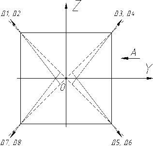
Fig. 4. Yaw control scheme
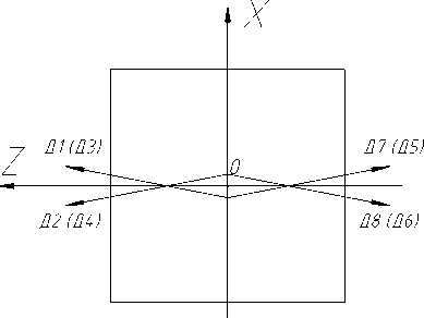
Fig. 5. Pitch and roll control scheme
To generate controlling moments along the axes Z and Y (pitch, roll), the thrusters shall be rotated by the same small angles to the + X and – X directions within the planes formed by their axes and the first-rotation axis (edges). Let it be the second rotation. For the purpose of certainty, let us rotate thrusters T1, T3, T5, T7 to the + X direction, and thrusters T2, T4, T6, T8 –tothe – X direction (fig. 5).
According to the scheme considered, we propose the following procedure of generating controlling moments to be used while performing inclination and longitude corrections.
Inclination corrections: pulse generation in the South direction (–Z): correction session is divided into two steps, in particular, during the first step the thrusters T1 +T2are active (time t1) and during the second step the thrusters T3 + T4 are active (12). If t, = t2, then the controlling moment is not generated, a “pure” thrust pulse is formed in the –Z direction. If t, ф t2, then the moment pulse +MX is generated, if t2 ф t,, then the moment pulse -MX is generated. The total moment pulse value is determined by the difference between times t1 and t2. As with each pair of thrusters fired the moment is generated, then over the entire duration of the thruster activation (t1 and t2) the wheel-based control system shall maintain the specified three-axis attitude of a satellite. If the system capacity is not enough to solve this task, then the correction session can be divided into a larger number of steps (4, 6, 8…) with the aim to reduce the moment pulse during the operation of each pair of thrusters to an acceptable value. The correction maneuvers are performed by a pair of thrusters (T1 + T2) or (T3 + T4) to prevent generation of moments along the axes Y, Z.
Similarly, generation of thrust pulses in the North direction (+ Z ) is ensured by the pairs (T7 + T8) ( t 1) + (T5 + T6) ( t2 ). With t , ф 1 2 the pulse of positive moment + M X is generated, with 1 2 ф t , the pulse of negative moment - M X is generated.
It is worth mentioning that as the thrusters have a thrust component along Y axis, a non-compensated thrust pulse in the longitudinal direction is generated at the expense of the difference between t 1and t 2whileperformingtheinclination corrections. To compensate this pulse impact, a special longitudinal correction session is most likely to be required.
Longitude correction:
– generation of thrust pulse in the West direction: (T3 + T4) ( t , ) + (T5 + T6) ( 1 2). With t , ф 1 2 the pulse of negative moment – MX isgenerated,withthepulseofpositive moment + MX is generated;
– generation of thrust pulse in the East direction: (T1+T2) ( t1 ) + (T7+T8) ( t2 ).Withthepulseofpositive moment + MX isgenerated,withthepulseofnegativemoment – MX is generated.
Inclination correction:
Generation of thrust pulse in the South direction is ensured by the pairs:
(T1+T3) ( t 1) +(T2+T4) ( t 2).Withthepulseofnegative moment – MY isgenerated,withthepulseofpositivemoment + MY is generated.
Generation of thrust pulse in the North direction is ensured by the pairs:
(T5+T7) ( t 1) +(T6+T8) ( t 2).Withthepulseofpositive moment + MY isgenerated, withthepulseofnegativemoment – MY is generated.
Longitude correction:
Generation of thrust pulse in the East direction is ensured by the pairs:
(T1+T8) ( t 1) +(T2+T7) ( t 2).Withthepulseofnegative moment – MY isgenerated,withthepulseofpositivemoment + MY is generated.
Generation of thrust pulse in the West direction is ensured by the pairs:
(T4+T5) ( t 1) +(T3+T6) ( t 2).Withthepulseofpositive moment + MY isgenerated, withthepulseofnegativemoment – MY is generated.
Inclination correction:
Following the selected layout, during the inclination correction maneuvers the generation of “pure” controlling moments in pitch is impossible.
Longitude correction:
Generation of thrust pulse in the East direction is ensured by the pairs:
(T1+T7) ( t 1) +(T2+T8) ( t 2).Withthepulseofnegative moment – MZ isgenerated,withthepulseofpositivemoment + MZ is generated.
Generation of thrust pulse in the West direction is ensured by the pairs:
(T3+T5) ( t 1) +(T4+T6) ( t 2).Withthepulseofpositive moment + MZ isgenerated, withthepulseofnegativemoment – MZ is generated.
Inclination correction :
In case of failure of one “North” thruster, the inclination correction can be performed without any limitations according to the above procedures using the “South” thrusters.
Longitude correction :
In case of failure of one “West” thruster (for example T1), the pulse in the East direction can be generated by the pair T2+T8orT2+T7. Inthefirstcase, themomentinpitch + MZ is generated, in the second case, the moment in roll + MY is generated. The moments mentioned shall be compensated using a wheel-based control system within its capability scope, the duration of the thrusters firings can be limited. The value of the moment to be compensated can be reduced twice by firing only one thruster, for instance T2, T7, T8 instead of firing a pair of thrusters. However, during the activation of any of the thrusters mentioned above, the moments along all three axes occur.
The similar situation takes place in case of failure of any “East” thruster. Limitations imposed by the ADCS can be avoided by implementing additional thrusters of longitude corrections, with the line of actions running through the SC center of gravity. However it will result in increasing the number of the orbit control thrusters to be used up to 10.
Thus, we can conclude that with the considered orbit control layout scheme, the correction in longitude and inclination are possible with and without generation of controlling moments of both signs along three axes. Moreover, the redundancy is provided in case of failure of one thruster used for the inclination corrections (without any limitations) and in case of failure of one thruster used for the longitude corrections (with limitations imposed on correction duration depending on the parameters of the wheel-based ADCS system). However in comparison with the initial scheme, the planning of the orbit correction maneuver sessions becomes more complicated as both generation of the thrust pulses in the required directions and generation of controlling moments of a specified sign are required.
Let us consider the possible advantages of the above mentioned scheme of the orbit control thruster locations. Let us use 8 thrusters as shown in figure 2 without any additional longitude correction thrusters. As the controlling moments are generated while performing the correction sessions (due to minor deviation of thruster axes from the nominal directions), then the propellant is not spent for the purpose of generating moments in the process of satellite nominal operation. That is why in order to compare the initial scheme with the considered one it is quite sufficient to compare a filled mass of monopropellant AC (attitude control) thruster unit with a mass of gas-jet system ensuring the initial modes and emergency modes. Due to task limitations (the required total pulse is small), the simplest solution is to use the same propellant (gaseous xenon), which is used for the OC (orbit control) electric-jet thruster unit. In this case, no additional tank is required (if sufficient volume of electric-jet thruster unit tanks is available). Let us assume that the tank capacity is sufficient to fill additional gas, and perform the above comparison for satellites based on the EXPRESS-1000 platform.
Cold xenon gas-jet system :
Gas feed unit: 3 kg; additional AC thruster units: 6 x 0.5 kg=3kg.
The total pulse required for orientation purposes in the initial and emergency modes depends on satellite mass, nozzle locations, quantity of the above mentioned mode occurrences. According to the estimations, for satellites of 1...2 tons, 100...200 kg∙s are required. Let us take the high value for the purpose of reliability. Xenon mass required to generate approximately 200 kg∙s and specific pulse 25 s under temperature 20 °C is 8 kg; pipe mass is ~3 kg. Totally: 17 kg.
Monopropellant AC thruster unit :
Thruster unit: 1,9 kg x 8, totally: 15,2 kg; storage and feed unit: 16,3 kg; pipes: ~3 kg; propellant: 25 kg; pressurant: 0,15 kg. Totally: 59,65kg.
Therefore, the difference in masses of considered propulsion subsystem configurations is approximately 43 kg. This value is the upper mass advantage estimate of the scheme with orbit control thrusters fixed, generating controlling moments, in comparison with the initial (baseline) scheme of individual independent attitude and orbit control thruster units with regard to satellites based on the EXPRESS-1000 platform. If an additional Xenon tank (16 kg) is required, then the advantage over the initial scheme is 27 kg.
Depending on the design of a specific platform, the mass advantage value achieved due to refusal of dedicated AC thruster unit and generation of controlling moments by OC thrusters can vary significantly. However, one can expect it to be 30...40 kg. With two additional OC thruster tanks installed in the scheme shown in figure 2 (one unit in the + Y direction, the other in the – Y direction) to ensure full redundancy of the longitude correction thrusters, then the advantage is close to the low value limit (30 kg).
The analysis has confirmed that the use of OC thrusters fixed on a satellite body with the aim of generating controlling moments is possible. Such solution can ensure mass advantage up to 30...40 kg (for a satellite of 1...2 tons) due to refusal of dedicated AC thruster unit. However, this advantage may cause dramatic complication of the orbit correction maneuver planning and implementation: each correction (up to 2 times a day over the entire lifetime) shall be planned separately with the involvement of specialists in charge of motion control and attitude control subsystem. Correction sessions shall be performed by pairs of thrusters only, it shall be ensured by TU power processing unit, and the required EPS power available. The correction sessions shall be divided into steps, the thruster firing duration shall be provided with the required accuracy, not less than several seconds or tens of seconds, at least. Coincidence of inclination corrections and wheel unloading operations requires additional longitude corrections. Automation of the correction sessions is rather difficult. The approach can be implemented only for the satellites not requiring rather long autonomous operation.
