Гибридный плазмонный волновод

Автор: Белан Сергей Александрович, Вергелес Сергей Сергеевич, Воробьев Петр Евгеньевич
Журнал: Труды Московского физико-технического института @trudy-mipt
Рубрика: Теоретическая и приклодная физика
Статья в выпуске: 1 (17) т.5, 2013 года.
Бесплатный доступ
Гибридный плазмонный волновод состоит из диэлектрического нановолокна высокой диэлектрической проницаемости, встроенного в диэлектрик с низкой диэлектрической проницаемостью вблизи поверхности металла. Эта архитектура рассматривается как один из наиболее перспективных кандидатов для дальнобойного направления. Дисперсионное соотношение основной моды гибридного волновода получается аналитически в квазиэлектростатическом приближении. Впервые, насколько нам известно, явно написано бесконечное множество линейных алгебраических уравнений для решения проблемы собственных мод в такой геометрии. Получено и обсуждено численное решение, основанное на этом подходе. Наш качественный анализ и численные результаты показывают преимущества специальной конструкции волновода, когда диэлектрическая проницаемость цилиндра больше, чем абсолютная величина диэлектрической проницаемости металла.
Короткий адрес: https://sciup.org/142186213
IDR: 142186213
Текст научной статьи Гибридный плазмонный волновод
The creation of the waveguides capable of guiding light with deep subwavelength confinement in the cross section is of great interest for practical applications. These devices may throw open the doors to nanoscale optical communications, quantum computing, nanoscale lasers and biomedical sensing. The main problem on the way to practical realization is the diffraction limit of light in dielectric media. Electromagnetic energy can’t be localized into nanoscale regions much smaller than the wavelength of light in the dielectric [1]. The possible solution to this problem is to use a material with negative dielectric permittivity. For example, metals are known to exhibit this property below the plasma frequency. Metal structures provide guiding of the surface plasmon-polaritons (SPP), which are localized near metal-dielectric interfaces and can be guided by metallic nanostructures beyond the diffraction limit [2]. However in practice it is a challenge to provide the deep localization with large propagation length due to the presence of Ohmic losses in metal.
For the simplest geometry like a metal films or wires [3] - [5] the deep localization can be achieved at restricted values of the metal permittivity em, whereas low propagation loss length needs large ratio of its real to imaginary parts, em/em. These two requirement cannot be satisfied simultaneously for most materials. The new approach for this challenge integrates dielectric waveguide with plasmonics one. The hybrid plasmonic waveguide consists of a high-permittivity dielectric nanofiber separated from a metal screen by low-permittivity dielectric nanoscale gap [6]. Both the single fiber and the silver screen cannot provide strong mode confinement at optical and near infrared frequencies, but the hybrid conductor-gap-dielectric architecture have experimentally demonstrated deep subwavelength optical waveguiding [8]. Relatively large propagation length has been achieved due to high ratio E' m /e' m at the chosen frequency and the specific spatial structure of the guiding mode.
In the present paper we propose and discuss another realization of the hybrid approach proposed in [6]. We show that the hybrid plasmon polariton)HPP) mode confinement can be considerably risen by a specific choice of the materials, when the dielectric constant of the cylinder is greater than the absolute value of the dielectric constant of the metal screen. The main advantage of the choice is the hyperbolic-like dependence of the effective index on the gap width. This feature allows to maintain arbitrary subwavelength mode size at any frequency by adjusting the gap width. This freedom considerably widens the range of possible materials which the waveguide can consist of. The geometry of the waveguide admits implementation of the loss compensation techniques based both on optical pumping [13] and on electrical injection [11], that makes our realization of the waveguide potentially interesting for applications. To justify our idea we theoretically investigate propagation of the HPP-mode. First we give qualitative analysis of the guiding mode basing on the consideration of planar sandwich-like conductor-gap-dielectric waveguide structure(CGD) [19]. We derive exact analytical expression for effective index of CGD-mode and give criterion when the HPP-mode is CGD-like. Finally, we present semi-analytical approach of calculation of the electromagnetic field structure for the fundamental HPP-mode, which is applicable to any set of parameters. Similar approach has previously been applied for plane wave scattering by a cylinder placed near plane surface [9]- [10]. Here we present the first realization of this method for waveguiding problem at system with the hybrid geometry. The scheme is based on expansion of the HPP-mode over single cylinder modes and the surface plasmon polariton modes of the metal screen and matching the boundary conditions for electromagnetic field components. Numerically obtained dispersion relations confirmed the advantages of our design of the hybrid waveguide.
2. Qualitative description
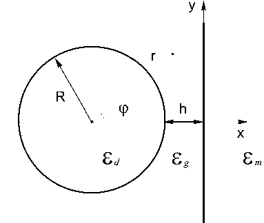
We consider the following geometry of the hybrid waveguide. A dielectric cylinder with circular cross-section is placed above a metal screen. The cylinder radius is R, and the width of the gap between the cylinder and the metal screen is h, see Fig.1a) for a cross section. We consider a plasmon-polariton mode, that propagates along the waveguide and is bound in the transversal plane. The frequency of the mode is ш and the propagation constant is /3- We choose the Cartesian reference system with z-axis directed along the waveguide, whereas x-axis is directed normally to the metal screen. Thus, all electromagnetic field components have dependence on time and z-coordinate as exp[i/3^ — iwt \. We assume, that responses of both dielectric and metal on electromagnetic field are described by dielectric constants, which are em and Ed correspondingly. Generally, the outer medium may be not vacuum, but some dielectric medium having dielectric constant being equal to eg. All the materials are assumed to be nonmagnetic. To describe the mode confinement, it is convenient to introduce effective refractive index neg, which is defined as neff = 3/к, where к = ш/с in the wavenumber in vacuum. The effective refractive index determines the field penetration depth into the materials with permittivity e as l/k^n ff — e. The penetration depth should be real in the unbounded waveguide constituents (metal and outer dielectric space), and may be imaginary for bounded constituents (fiber). Thus the greater neff is the stronger field localization is in the transversal plane.
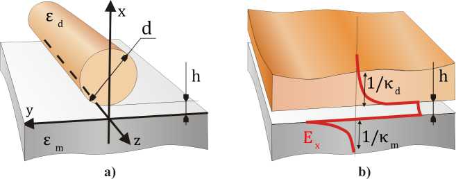
Fig. 1. a) The hybrid waveguide, b) Plain waveguide with the same width of the gap
Optimization for transversal confinement implemented in [6] for hybrid waveguide shows that the thinner gaps provide higher localization. The fiber radius is much greater than the gap width in the case and the waveguide shape is close to plain sandwich like conductor-gap-dielectric (CGD) structure in the gap region. The limit of plain CGD-structure was considered in [19], where the properties of the bound fundamental mode were investigated. One of the main advantage of the mode is that effective index of the mode icgd is greater than the refractive index of the dielectric id = ^Ed, icgd > id- This implies, that the electromagnetic field of the mode decays exponentially into the dielectric cladding. Nevertheless, the analysis proposed in [19] is not applicable to mode of waveguide with optimal parameters found in [6]. The reason is that the mode of plain CGD-model indeed describes the HPP-mode only for large enough fiber diameter d otherwise HPP-mode should be considered as a result of hybridization of surface plasmon polariton modes and the modes of the dielectric cylinder.
The main goal of the present work is to give the theoretical description of the hybrid waveguide and to find approaches to deeper localization of the HPP-mode. Comparative analysis of [6, 19] suggests, that in order to get stronger transversal miniaturization of the hybrid waveguide the CGD-like regime of propagation should be achieved for the radius which is much less than free space wavelength. Our analysis of the plain CGD-structure shows that the localization of the fundamental mode can be significantly risen for special set of materials, when absolute value of the metal dielectric constant is less than the dielectric constant of the dielectric cladding, |Em| < Ed. For the case, the effective refractive index icgd is proportional to inverse width of the gap, icgd к 1/kh, when the width h is small enough. To use the same effect for the hybrid waveguide, the cylinder diameter should sufficiently exceed some critical value d*, which is determined by the condition that the transversal size of the plain part of the gap is comparable with the mode penetration depth into the dielectric 1/Kd. The size of the plain part of the gap is evaluated as 2Vhd, thus the condition is 2Vhd* ~ 1/Kd. For d greater enough than d* the guiding mode can approach the strongly confined mode of the sandwich like system even if the diameter of the cylinder is much less than free space wavelength.
In order to give general physical argumentation of our results let us consider planar sandwichlike CGD-waveguide in details. The wave vector of fundamental CGD-mode (which is TM-mode) can be calculated from equation [19]
exp[2hKg ] =
(EdKg - Eg Kd)(EmKg - Eg Km)
(EdKg + Eg Kd)(£m Kg + EgKm)
where Kt = k^nCGD — Ei for each material, г = ‘m’,‘g’,‘d’ and nCGD is the effective index of the mode. In particular, 1/Kd and 1/кт are the penetration depth into the dielectric and the metal correspondingly. It is known that such plane three-layer waveguide supports the propagation of the bound eigen mode only if the width of the intermediate layer is less than some cut-off value hc which is determined by the permittivities at given frequency hc
A
4^Ed — Eg
log
Em VEd — Eg — Eg VEd — Em
Em V Ed — Eg + Eg V Ed — Em
When thickness exceeds this critical value the fundamental CGD-mode becomes radiative with energy leaking into upper dielectric half space.
There is a significant difference between the dependence of the effective index nCGD on the gap thickness h for the cases of low and high index dielectric. For relatively low refractive index of dielectric, when Ed < |Em|, there exists surface plasmon-polariton mode when the gap is absent, h = 0. It has effective index nmd = ^Em Ed/(Ed + Em). Then the effective index of the fundamental CGD-mode is bounded, id < iCGD < nmj. Just the case was considered in [19] and [6]. Otherwise when permittivity of dielectric is relatively high
Ed > |Em| > Eg,
the effective index iCGD unlimitedly diverges as the gap thickness tends to zero, h ^ A/^Ed:
lCGD
1 in (Ed — Eg )(Em — Eg) 2kh (Ed + Eg )(Em + Eg)
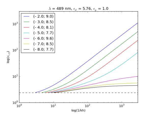
Fig. 2. Thickness dependence of the CGD mode’ effective index
It leads to extremely strong light confinement in a transparent dielectric gap layer located between the high-index dielectric and the conductor. The actual degree of localization is restricted only by additional factors, such as increasing Ohmic losses in the metal, spatial dispersion and atomic structure of the materials. This feature is the principle behind our idea: in practice one should choose the metal with the absolute permittivity less than the permittivity of the cylinder and place cylinder at distance h < h c from the metal plane. When such metal is involved the effective index of the HPP mode can be significantly greater than effective index of electromagnetic field in bulk material of the cylinder even for very small diameters of the cylinder.
However there is reverse side of the strong localization which is small propagation length. It was shown in [6] that the strongest localization of the HPP-mode corresponds to the lowest propagation length. It is common place of waveguides which use metal as a constructive component. Let us consider limit when the gap index is low, so eg ^ |em|. For the case n to 1 fl — |em1 + г i (5) CGD ~ khlEm|\ Ed |sm J where Emm is the imaginary part of the metal permittivity. It follows from Eq. (5), that the localization radius is of the order of h|em| in the limit h ^ hc. Note, that our approach allows to squeeze the mode at arbitrary frequency into any subwavelength scale simply by tuning the gap width in accordance with (4). Hence, our waveguide design breaks connection between mode localization and the carrying frequency of the mode. In particular, the approach may be interesting for design waveguides at THz frequencies [20,21]. The propagation length I ^ h|eml/ltg| i.e. reduces with the mode size reduction. To keep the propagation length acceptable for practical implementation at fixed localization radius one should minimize loss tangent tg. Thus, a prospecting like [22] is needed to propose the optimal choice of materials for our approach (3).
3. Theoretical description
In the section, we discuss the semi-analytical approach to the problem and present the numerical results. It follows from Maxwell’s equations that the electromagnetic field of propagating modes can be fully described by ^-components of the electric and the magnetic fields, Ez a nd Bz [14]. Both of these fields satisfy the following two-dimensional Helmholtz
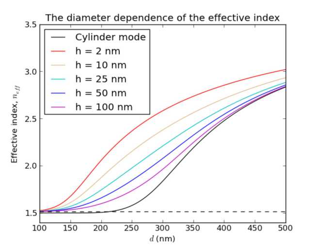
Fig. 3. Effective refractive index of the fundamental hybrid mode versus cylinder diameter d (coloured lines) compared with those of single fiber (black solid line) and SPP mode(lower black broken line). The dielectric constant of the cylinder, dielectric and metal are Ed = 12.25 Eg = 2.25 and Em = -129 + 3.3г respectively at wavelength A = 1.55 pm. These parameters are chosen in accordance with [6]. The critical gap width hc = 5nm. The HPP-to-CGD crossover point: d* ~ 17pm for h = 2nm differential equation inside the homogeneous areas where dielectric permittivity is constant:
pHz} -(й 2 - Ek2 1Hz }=°- 161
In (6) A± = d2 + 8^ and к = ш/с is the wavenumber. The boundary conditions on the both interfaces are continuity of components EZi HZ. eE ^ and H^ where ^-component of a vector is its normal component.
Our semi-analytical method is based on the representation of the hybrid waveguide as an integration of the dielectric fiber and plane plasmonic waveguide. We express the electromagnetic field of the HPP-mode as a linear combination of cylindrical mode around the fiber and evanescent plane waves above the metal screen. Boundary conditions provide the system of linear equations on the expansion coefficients. Such an approach leads to highly efficient method of numerical solving a difficult boundary-value problem that describes the propagation of waves in a complex systems [15]- [16]. The scheme is developed in details in Appendix 1.
To verify our semi-analytical method, in Fig.3 we present the dependence of the effective index of the fundamental hybrid mode on the cylinder diameter d = 2R for a range of the gap widths h in the case of telecommunication wavelength when e g < Ed < |em|. These dispersion curves are obtained from our numerical procedure and show good agreement with the results obtained in [6] by using finite-element package FEMLab from COMSOL.
In accordance with our general argumentation given in Section 2 we present two sets of plots. Fig.4 corresponds to the case of fiber with comparatively low refractive index, Ed < |em|, the parameters of the waveguide are taken in accordance with experimental work [13]. Fig.5 corresponds to opposite limit, when E d > |em|. Parameters of these two plots differ only for metal permittivity Em, the value Em = —4 is chosen for Fig.5. Here, we do not concretize the material of the metal screen, our goal is just to demonstrate the qualitative difference of the guiding mode properties for the case (3).
Finding results indicate that when fiber diameter d is decreased, the HPP-mode loses confinement along the metal and eventually (at d = 0) becomes a surface plasmonpolariton mode of the flat metal-gap interface. Herewith the effective index of the HPP-mode monotonically decreases to that of this SPP-mode. Thus all dispersion curves have the same asymptotic neff ^ nmg = д/ emEg / (em + Eg ) at small d. Two different characters of behavior are
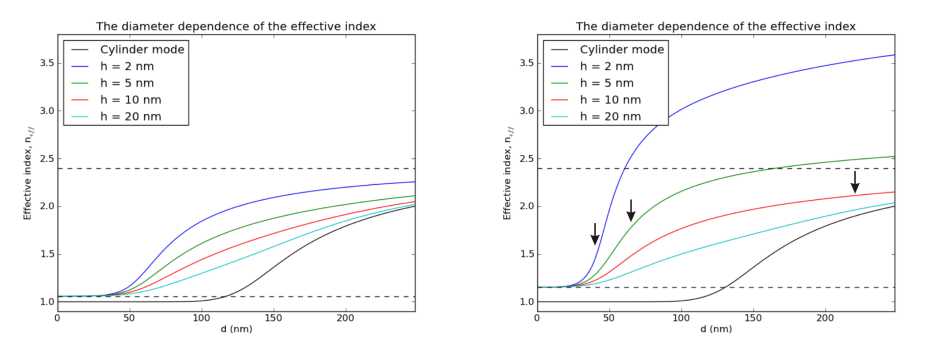
Fig. 4. Wave vector of the fundamental hybrid mode versus the cylinder diameter d (coloured lines) compared with those of single fiber(black solid line) and SPP mode(lower black broken line). The dielectric constant of the cylinder, dielectric and metal are ed = 5.76 e g = 1 and em = -9.2 respectively at wavelength A = 0.49/zm. These parameters are chosen in accordance with [13]. The critical gap width h c = 7nm. The HPP-to-CGD crossover points are: d * ~ 310nm for h = 2nm , d * ~ 875nm for h = 5nm.
Fig. 5. Wave vector of the fundamental hybrid mode versus cylinder diameter d(coloured lines) compared with those of single fiber(black solid line) and SPP mode(lower black broken line). The dielectric constant of the cylinder, dielectric and metal are ed = 5.76 eg = 1 and em = —4 respectively at wavelength A = 0.49цт. The critical gap width hc = 13,4nm. The HPP-to-CGD crossover points (black arrows) are: d* ^ 40nm for h = 2nm, d* ~ 65nm for h = 5nm, d* ~ 220nm for h = 10nm possible at the opposite limit of large diameter. As the diameter d ^ to, the HPP-mode can asymptotically tend either fundamental single fiber mode or the fundamental mode of the planar three-layer system, the choice depends on the gap width h. If the gap thickness h is less than hc (Eq. (2)), the HPP-mode approaches the CGD-mode as the diameter increases. If the crossover between the asymptotics occurs at d* (black arrows in Fig.5) which is determined as
d* «
4(nCGD — ed )hk 2
For h > h c the HPP-mode becomes cylinder-like in the limit of the large diameter. In the case the critical diameter d0 corresponding to the transition between small-diameter and large-diameter asymptotics is defined by the equation nSF (do) = nmg where nSF (d) is the diameter dependence of the effective index of the single fiber fundamental mode. If the condition /ed kd ^ 1 is valid, we can show that the localization of this mode is exponentially small, nsF = л/e g + K g /(2^sg k ), where
K g /k «
16e-2^+1 ,—n .y> exp
V^g(kd)2
f _8Cd_+fg)_ 1
I eg(ed — sg)(kd)2J ^ ,
and 7 = 0.5772... is the Euler-Mascheroni constant.
Next let us assume that effective index of the CGD-mode is significantly larger that the refractive index of the fiber medium. This can be achieved by diminishing the gap thickness in the case (3). Then the CGD-mode have strong confinement so the crossover diameter can be decreased to deep subwavelength scale, d* ^ A, by tuning the gap width. Therefore the attractive CGD-like asymptotic is achieved by HPP-mode with very small diameter of cylinder providing the wished structure of the mode with the strong transversal localization in two dimensions within the gap region and exponential decaying into the cylinder. Note that in the case the particular shape of the top part of the fiber cross section which is at distances much larger than 1/«d from the gap does not play role any more [19].
4. Longwavelength limit
In this section we demonstrate the solvable limit of the hybrid waveguide. Assuming quasielectrostatic approximation y/E d kd ^ 1 to be valid one can consider the second term in the Helmholtz equation as the perturbation of the Laplace operator. Then longitudinal components of the electromagnetic field to a zero approximation are defined by the two-dimensional Laplace equation:
A1 { 5} = °,
Let us suppose the electromagnetic wave frequency to be much below the plasma frequency, so the metal can be considered as the perfect conductor. It physically corresponds to the condition |Em| ^ E d , E g. Thus under this assumption our problem reduces to boundary-value problem of cylindrical dielectric waveguide placed parallel to the surface of a perfect conductor. It should be also mentioned that, in fact, our problem is equivalent to finding the eigenmodes in the system of two identical parallel dielectric waveguides separated by a distance 2h. Those eigenmodes of this system for which the tangential electric field components are vanishing in the symmetry plane are the eigenmodes of our system too. It is because the symmetry plane can be replaced by a perfect conductor plane without causing any effect in this case.
The smallness of the parameter y/E d kd ^ 1 allows us to develop the perturbation theory and take into account the retardation in the Helmholtz equation. The details of the approach is given in Appendix 2. Imposing the boundary conditions on the perfectly conducting metal surface we find the following dispersion relation for the fundamental dipole-like mode
1 ( e^0 (Ed sinh 60 + Eg cosh £,))
"eff — . ' I--2Eg (Ed - •J where pre-exponential factor is inaccurate because of logarithmic accuracy of our calculations and the notations
«= УЩ+Һ , 6, = 1п VX+h+ (.Ш)
h(d + h)
are introduced.
The form of this result is similar to the dispersion relation of the fundamental mode in single thin fiber (Eq.(8)) which can be obtained within the same perturbation method in long-wavelength limit or as the expansion of the exact formula.
The parameter neg — ^УУ is actually a measure of localization of the investigated mode. It determines the difference between wave vector of the plane-wave in the outside region and wave vector of the guided mode. The ratio к ^^nff — eg gives an estimate for a depth of penetration of the mode into outside region. Thus, decreasing the radius of cylinder leads to deeper penetrating of the mode into the surrounding space. The same is true for the decreasing the separation h. So there is no subwavelength guiding in this system in quasi-electrostatic limit.
5. Conclusion
In the paper we have proposed the novel approach for hybrid plasmonic waveguide design providing wide opportunity for HPP-mode size controlling. When the permittivity of the dielectric is greater than the real part of metal permittivity the hybrid effective index is unlimited(Eq.(4)) and can be tuned by the waveguide geometry at fixed frequency and materials constituting the waveguide. This feature of the case (3) is confirmed by both qualitative analyse within planar three-layer model and rigorous semi-analytical method describing the HPP-mode propagation in general. We have described the different regimes of guiding and derived the estimation for HPP-to-CGD crossover diameter(Eq.7).
In order to find the dispersion relation of fundamental hybrid mode for the case |em| » Ed, e g we have developed perturbation theory using smallness y/e d kd ^ 1 within quasi-electrostatic approximation. The same perturbative approach could also be applied to various range of problem for which Helmholtz differential equation is not separable. The dispersion relation of the hybrid waveguide finding within approximation of the perfectly conducting metal is similar to that of the single optical fiber. It is due to the fact that perfect metal does not support the plasmonic waves and then the hybrid waveguide is pure dielectric one with very weak localization in long-wavelength limit.
The work was supported by Russian Ministry of Education and Science.
1. Numerical method
The theoretical description of the hybrid waveguide is inhibited by its complex geometry. In general we should chose such system of coordinates where the surfaces of the waveguide are the isolines and Helmholtz equation can be solved by separation of variables. The hybrid geometry corresponds to the so called bipolar coordinates based on two sets of orthogonal circles. In this coordinate system the Helmholtz equation has quite complicated form and accordingly the set of eigen functions can’t be found analytically. However the unknown hybrid eigen functions can be expressed in terms of known solutions of the Helmholtz equation in other coordinate systems. It is convenient to represent the total electromagnetic field of HPP-mode as the superposition of the all modes of single fiber)cylindrical functions) and all SPP modes(evanescent plane waves) with some unknown coefficients of expansion.
Supposing the structure of the fundamental hybrid mode to be symmetric with respect to ж-axis we can describe the longitudinal component of the electric field as
M d = ЕП=о M-E (XdE)cosn^
EM= ЕЮ=о bnK4K g r) cos n^+ + J^ c® exp(QKg (ж — D)) cos qK g y dq eM = / 0 ю d^ exp(—Qкm(ж — D)) cos qKmy dq
and ^-components of the magnetic field as
HM = ЕП=о “пШ^ sinny
M^ = ЕЮ=0 bn En(K g r) sin nV+ + О Ю c^ exp(Qкg(ж — D)) sin qK g y dq
H mm = f^d^ exp(—Qкm(ж — D))sin qKmy dq
where Q = \/1 + g2 and D = d/2 + К.
То write the corresponding equations, it is convenient to express the fields inside dielectric in terms of only plane evanescent waves, when we impose the continuity conditions on the boundary of the metal, and in terms of angular harmonics, for the cylindrical surface. We solve it by using the evanescent plane wave expansion of modified cylindrical functions and angular harmonic spectrum of the evanescent plane waves [18].
K„ (Kg r)e"*-
Z +^
∞
(g + Q)n 2Q
e~ Q"g x + iqKg у ^g.
Using this formula be obtain
Kn (ngr) cos np =
∞
/ ҒУ (g)
J 0
e-QKg X
cosдк8 у
dg,
where
Kn (ngr) sin np =
∞
/ FP (gK^g
sin gKg у dg,
F E
Ft
F H
П
Q - g' + Q g'
2Q ’
(Q + g)n - (Q - g)n
2Q
We also need to expand the SPP modes into a series of the angular harmonics e^- cosgKgу = £ GEcosnp,(19)
n=0
■"X sin gKgу = T^GH sinnp,(20)
n=0
where
GE Ғ-ҒҒ ((Q + g)n + (Q - g)n)/n (Rgr),(21)
GH = ((Q + g)n - (Q - g)")7„(Kg r).(22)
Electromagnetic fields in surrounding medium close to the dielectric waveguide can be written as
£(g) = £ bEK„(Kgr) cosnp + n=0
∞∞
+ cosnp / cEGn(r,g)e~^KsD dg n=0 0
H^g — ^ bn ^(«gr)sinn^ + n=0
+ у sin w, [” c®.• ...■• dq n=0 0
The corresponding expressions for the fields close to the surface of the metal are:
∞∞
’ ■ 1. у
b® F^ q x
cos q/g у dq +
+
∞
Vo
CE eQKg ( x-D )
cos q/g у
dq,
∞∞
J 0 n=0
sin qtg у dq +
+
∞
CH e^gix-D")
sin qtgy dq.
It can be easily derived from the Maxwell equations that for the normal component:
_ ip 3EZ i k 3HZ
^ P2 — ek2 8^ P — — ek2 ду 1
_ ik 3EZ ip 3HZ
^ eP2 — ek2 ду P2 — ek2 3k where у is tangent to the interface coordinate in the transversal plane.
The continuity conditions on the metal surface for EZ, BZ, Ey and By lead to the first system of linear homogeneous equations (SLE) on coefficients b®, b®, c®, c® , d®, dp. The corresponding continuity conditions for EZ, BZ, Ev and Bv on the cylindrical surface produce the second SLE on amplitudes a®. a®. b®. b®. c®. c®. which is now integral with respect to c®. c®. In order
L L L L U U U U to avoid integration of the unknown functions we express the coefficients c®, c® in the terms of b®, b® from the first SLE and substitute them into the second SLE. The procedure leads to the infinite system of linear homogeneous algebraic equations for coefficients a®, a®, b®, b®. In order to solve the system numerically finding the dispersion law, one should truncate this system to a finite size N.
2. Perturbation theory
To solve Laplace equation we use so-called bipolar coordinate system [12] which is convenient for two reasons. First of all both circular line of cross-section of the cylinder and straight boundary of the metal are the lines of the constant value of scale coordinate of this system for particular choice of definite parameter. Secondly bipolar coordinates allow the separation of variables for Laplace equation.
The scale factors in bipolar system of coordinates are equal to h^ — hy —
a cosh £ — cos у1
and Laplacian is given by
A±
(cosh £ — cos у)2 3 2 3 2
a2 Зу2 3®2
Let ^о corresponds the line of cross section of the cylinder. We than find a = у/ h(d + h), ^Md + h) + h
S0 = ln , =----.
^ h(d + h) — h
Using the boundary conditions on the perfectly conducting metal surface we have for z- components of the electric and magnetic field of the dipole mode to zero approximation:
E' ( 0 = f
|
E ^0)™- = A™e € cos p, E(0)out = A 1 ut sinh S cos p |
(29) |
|
H(p°™ = Bi«e-e sin p, HA°oolt = B0ut cosh S sin p |
(30) |
H ' = f where we denote field inside the cylinder by notation ”гп” and the field outside by ”out”.
Next we should find the terms of first order for which we have the inhomogeneous Laplace equations:
-
(1) (0)
E=2—■ E <31>
It seems to be impossible to solve these equations analytically in the bipolar coordinates because of the complex form of scale factor (25). But one can note that the functions in their right-hand parts can be rewritten as
E
(0)in
г
E(0) =
= АІД1 — 2a c^^),
E (0)out дои-t a(cos ^+ I г 1p. '
H0 =
н^
2B™a
sin ф - p -
ц(0)out o?
H = Bx a( — +
cos ^. p -
),
sin ^- p -
) .
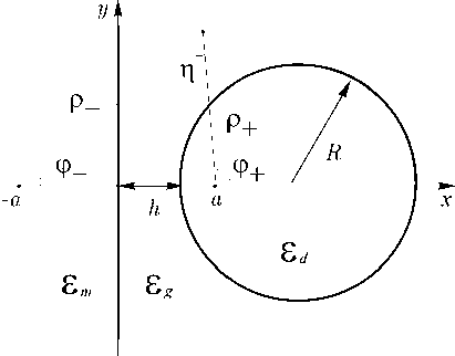
Fig. 6. Reference systems
These functions coincide with superposition of zero terms of the Maclaurin expansions of the cylindrical functions:
KppE^ = 1 • e^ + 1 plnap • e^ + ...,
p
Fi(p)e^ = — 21 • e^ + 1 plnap • e^ + ...,(31)
^ p^
_ , . _p
J 0 (p) = 1 —4 + ...
where K 1 (p) is Macdonald function, J o (p) and Y 1 (p) are Bessel functions of the first and second kind respectively [17].
This fact plays a very important role in the following. Cylindrical functions (34) are solutions to two-dimensional Helmholtz equations (6) and zero order terms of their Maclaurin expansions are identical to solutions to Laplace equations (9). Therefore, first order terms in the expansions of these cylindrical functions are the partial solutions of the Poisson equations (31). Then we find with logarithmic accuracy
E^ = <
H 1 = <
E^1m = A^ax2p- ln xp- • cosy-, yW0"* = 1A"“*aK2(p In Kp- • cosy— + +p+ In Kp+ • cos y+),
H(1m = -Bl1nax2p- lnxp— • sin y—, н(1)о»4 = lB0utaK2(p- ln«p— • siny— + +p+ ln«p+ • siny+), where
X2 = едк2 — ^2, k2 = ^2 — Eg k2 .
It is clear that the fields Ez = E® + E^1) and Hz = H0) + H1) satisfy the boundary conditions at the metal interface. Thus we now need to impose the boundary conditions on cylindrical surface.
We finally find with logarithmic accuracy к ~
1 e^0 (ед sinh Д + eg cosh £o)
a P 4eg (ед — Eg)k2 a2
)
Список литературы Гибридный плазмонный волновод
- Born M., Wolf E. Principles of Optics. -Cambridge Univ. Press, 1999.
- Gramotnev D. K., Bozhevolnyi S. I. Plasmonics beyond the diffraction limit//Nat. Phot. -2010 -V. 4.
- Economou E. N. Surface plasmons in thin films//Phys. Rev. -1969.
- Burke J. J., Stegeman G. I., Tamir T. Surface-polariton-like waves guided by thin, lossy metal films//Phys. Rev. -1986.
- Takahara J., Yamagishi S., Taki H., Morimoto A., Kobayashi T. Guiding of a onedimensional optical beam with nanometer diameter//Opt. Lett. -1997.
- Oulton R. F., Sorger V. J., Genov D. A., Pile D. F. P., Zhang X. Hybrid plasmonic waveguide for subwavelength confinement and long-range propagation//Nat. Phot. -2008. -V. 2.
- Oulton R. F., Bartal G., Pile D. F. P., Zhang X. Confinement and propagation characteristics of subwavelength plasmonic modes//New J. Phys. -2008.
- Sorger V. J., Ziliang Y, Oulton R. F., Bartal Y. W. G., Yin X., Zhang X. Experimental demonstration of low-loss optical waveguiding at deep sub-wavelength scales//Nat. Comm. -2011.
- Borghi R., Gori F., Santarsiero M., Frezza F., Schettini G. Plane-wave scattering by a perfectly conducting circular cylinder near a plane surface: cylindrical-wave approach//J. Opt. Soc. Am. A. -1996. -V. 13.
- Borghi R., Santarsiero M., Frezza F., Schettini G. Plane-wave scattering by a dielectric circular cylinder parallel to a general reflecting flat surface//J. Opt. Soc. Am. A. -1997. -V. 14.
- Fedyanin D. Y., Krasavin A. V., Arsenin A. V., Zayats A. V. Surface Plasmon Polariton Amplification Upon Electrical Injection in Highly Integrated Plasmonic Circuits//Nano Letters -2012. -V. 12.
- Morse P. M., Feshbach H. Methods of Theoretical Physics. -New York: McGraw-Hill, 1953.
- Oulton R. F., Sorger V. J., Zentgraf T., Ren-Min Ma, Gladden C., Dai L., Bartal G., Zhang
- X. Plasmon lasers at deep subwavelength scale//Nat. -2009.
- Marcuse D. Light Transmission Optics. -New York: Van Nostrand Reinhold, 1972.
- Zakowicz W. Two coupled dielectric cylindrical waveguides//J. Opt. Soc. Am. A -1997 -V.14, N. 3.
- Bulushev A. G., Dianov E. M., Okhotnikov O. G. Propagation of the radiation in two identical coupled waveguides//Sov. J. Quantum Electron. -1988.
- Abramovitz M., Stegun I. Handbook of mathematical functions, 1979.
- Borghi R., Frezza F., Santarsiero M., Schettini G. Angular spectrum of modified cylindrical wave-functions//International Journal of Infrared and Millimeter Waves -1999. -V. 20, N. 10.
- Avrutsky I., Soref R., Buchwald W. Sub-wavelength plasmonic modes in a conductor-gapdielectric system with a nanoscale gap//Optics Express. -2010.
- Ishikawa A., Zhang S., Genov D. A., Bartal G., Zhang X. Deep Subwavelength TerahertzWaveguides Using Gap Magnetic Plasmon//Phys. Rev. Let. -2009. -V. 102.
- Nam S. H., Taylor A. J., Efimov A. Subwavelength hybrid terahertz waveguides//Optics Express. -2009. -V. 17.
- West P. R., Ishii S., Naik G. V., Emani N. K., Shalaev V. M., Boltasseva A. Searching for better plasmonic materials//Laser Photonics Rev. -2010 -V. 4, N. 6.
