Handover Analysis for Yaw-Shifted High-Altitude Platforms

Author: Yasser Albagory
Journal: International Journal of Computer Network and Information Security(IJCNIS) @ijcnis
Article in issue: 8 vol.6, 2014.
Free access
High-Altitude Platforms (HAP) is an emerging technology for mobile broadband communications and is capable of providing many advantages compared to conventional terrestrial and satellite systems. On the other hand, positional instabilities of HAP affect the system performance greatly. In this paper, a main problem concerning the rotation motion or yaw-shiftof HAP is described, analyzed, and its impact on the handover of cellular systems is also investigated. The total handover due to both user mobility and platform rotational positional instability is discussed and determined. An expression for the number of calls subjected to handover is deduced where it will be a function of users' density and their distribution in the cell, platform angular shift due to rotation, cell geometry, and number of active calling users. The analysis of this number shows the serious effects of the yaw-shift instability on the system performance.
High-Altitude Platforms, Mobile Communications, Positional Instabilities, Handover
Short address: https://sciup.org/15011325
IDR: 15011325
Text of the scientific article Handover Analysis for Yaw-Shifted High-Altitude Platforms
-
I. Introduction
High-altitude platform (HAP) is a new promising technology for providing wireless mobile communications services [1-8]. It is efficient in many terms including system deployment, communications performance and infrastructure cost. The radio coverage characteristics of HAP is superior to both terrestrial and satellite systems due to the capability of line of sight communications as in the satellite systems, but at lower propagation loss due to the relatively lower altitudes (2060 km). Directing beams toward intended locations is obtained by using either spot beam antennas or a twodimensional phased array that forms the desired cells on the earth surface. As it is an airborne body, the main problem with platform communications is the station keeping operation needed for proper and stable radio coverage. This in turn requires continuous monitoring for the platform attitude. Providing corrections to the platform attitude consumes part of the power supplied to the platform by the solar panels or fuel cells. As a consequence of this power consumption, the power efficiency is reduced. The attitude instability may be due to horizontal drift, vertical motion, platform inclination, and rotation around its vertical axis due to the change in
wind direction. Out of these, the most stringent one is the latter.
The rotation of the platform may have very serious effects on the system performance especially for the outermost-formed cells (i.e. the cells formed by beams of lower elevation angles). This yaw-shift can be corrected by re-directing all the beams forming the cells on the ground to cover their correct specified locations mechanically by steering the antennas payload or performing handovers to the mobile users of those moving cells, which on the other hand indicates very large number of handoff calls. Another problem regarding the use of stratospheric platforms in cellular communications is the increased system complexity as it works as a multiple base station unit, therefore, the users location information will be very sensitive to the beam pointing errors resulted from the positional instability of the platform.
Therefore, in this paper, we will analyze the handover process due to instability effects especially the yaw-shift. The paper is arranged as follows; in section II, the HAP cell geometry is described. In section III, the yaw-shift of HAP is modelled and section IV depicts its impact on the system handover. Finally, concluding remarks are dawn in section V.
-
II. Geometrical Description Of Hap Cells
The HAPs wireless communication system utilizes directional, as well as phased antenna arrays to construct its ground cells [9-13]. Directional antennas may be in the form of spot-beam antennas such as parabolic reflectors, horn antennas, lens antennas which give the desired directional pattern. The use of directional antennas has some advantages such as its practical availability and simplicity but on the other hand a failure in one of them results in a coverage hole due to the absence of the beam used in forming its cell. Ground cells also can be formed by directing a beam using adaptive or phased arrays which has a widespread use [14] where the coverage beam is formed by a number of antenna elements therefore any element failure in the array will slightly distort the beam pattern (the beam will have slightly larger beamwidths) and this can be an advantage compared with the use of directional antennas. In this paper, we will apply spot-beam antennas to form the ground cells as it is feasibly realizable and available for many applications and provide less complexity to the system.
Considering a HAP that is located at an altitude about 20 km high, at point P as shown in Fig. 1, where the footprint of a beam formed by any of the mentioned antennas onboard the HAP is shown.
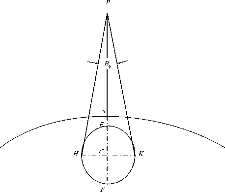
Fig 1: HAP cell footprint
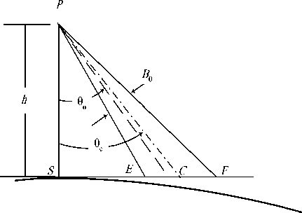
Fig 2: Flat ground approximation geometry
The HAP is located at an altitude about 20 km high, which is very small compared with the earth’s radius, we can approximate the earth as a flat surface as shown in Fig. 1. In this figure, the footprint of a beam formed by any of the mentioned antennas onboard the HAP is shown. The cell as depicted in Fig. 2 is defined by the
„ 9
coverage beam that has a direction of o and cross BB section beamwidth of 9 and ф, and the projection of the beam on the ground will be an ellipse that has a major axis EF and minor axis HK . Denoting the distance EF as bF which is given by
b F = h
( B. 1 ( tanl 9„ + — | - tanl 6„ o2 o
B θ
where the subscript F stands for flat ground approximation and h is the platform altitude in km.
The cell center point, C, is located by an angle from the platform given by
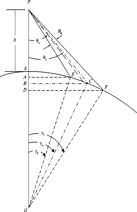
Fig 3: Curved earth coverage geometry
9 c = tan - 1 l tan l 9 o
B 9
+ bF-
2 h
and the cell minor axis distance HK can be denoted as a F and can be given by
aF
= 2 h sec ( 9 c ) tan l —
These two quantities (i.e. the minor and major axes) will define the cell shape and this assumption can be used for smaller and moderate coverage areas but when the coverage area increases the approximation error will increase and can’t be longer used and instead we apply the curved-earth cellular model where we take into consideration the earth curvature. A side view is shown in Fig. 3, which depicts the geometry used to define the cell parameters. In this figure, the major axis will be the arc
between the two ground central angles Y l and Y 2 which can be deduced as
Therefore the cell minor axis, aC , will be and
Y 1 = sin
|V h
1 11 + — | sinl 0„
Ц R J I o
B 9
9 o + ^
or
aC
= HK = 2 PC tan
I

-1
Y 2 = Sin
J, h VC l 1 + — | sin| 9
. I R J I

9 o
aC = 2 h sec ( 9 c ) tan
B
V 2 J
where the cell center has a ground center angle given by
Yo = 2 (Yi + Y 2)
and we can get the distance PB as:
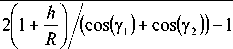
PB = h + R |1 -1 (cos(y1) + R cos(y2))J(7)
and the distance BC will be
BC = 2 R (cos(Y1) + R cos(Y2))tan(Y o)
therefore the platform-to-cell center slant distance will be
PC = 7 PB2 + BC2(9)
which can be also given by
aC
= 2 R tan l —
V 2
1 (cos(Y1)
from the above equations, the cell major axis, bC , can be defined as
- c = EF = R ( у 2 -Y 1 ) (10)
or
I -V. h bc = R sin 11 | 1 +— | sinl 9„ +
C I R JI o

B 9
-1 sin 1
V h V I l 1 + — | sinl 9„
C R J I o
B 9
and in this case the value of 9 c will be
9 c
= tan

or
9 c = tan - 1 <
tan (y 0 )
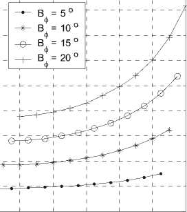
The cells described by (11) and (16) are more accurate than those given in (1) and (2) especially at lower elevation angles. Fig. 4-a and b depict the variations of the cell major axes with the beam direction o at different beamwidths B9 for both coverage models using directional antennas. The variations in this figure indicate the increase in the footprint with increasing both the beam direction and the beamwidth. The difference (or the absolute distance error) between the two quantities in km is shown in Fig. 5-a while the relative error in the cell major axis between the two models may be defined as:
e6 = -C---F x 10Q % (17)
bC where its variation with both the beam direction and beamwidth is shown In Fig. 5-b. In this figure, the error may approach about 2 % of the major axis for beamwidth of 20 o at a beam direction of about 60 o which corresponds to 700 meter difference. This large difference between the two expected major axis values for the two models will affect the system design especially for the cells at the coverage border or edges. On the other hand, the error is much smaller for the inner coverage cells and for cells of narrower beamwidth. For example a beamwidth of 5 o generates cells that have an error not exceeding 12 meters for direction no more than 40 o as depicted in Fig. 5-a. The same analysis is done for the cell minor axis as depicted in Fig. 6-a and b and the error (absolute and relative) for the two models is shown respectively in Fig. 7-a and b.
One can therefore utilize the simple equations used in the flat ground model for the range of moderate and acceptable error (such as for cells near the coverage center) while for larger error we can utilize the better curved earth model thus optimizing the use of both models.
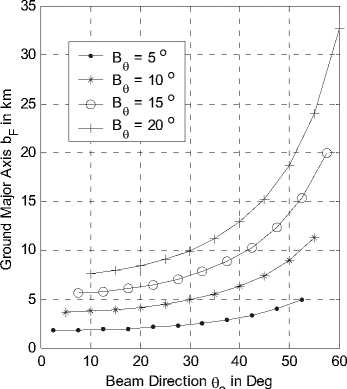
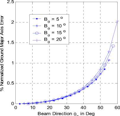
Fig 4-a: bF variation with beam direction at different beamwidths.
Fig 5-b: Relative error variation with beam direction at different beamwidths.

Figure 4-b: bC variation with beam direction at different beamwidths.
Е
0 10 20 30 40 50 60
Beam Direction θo in Deg
Figure 6-a: aF variation with beam direction at different beamwidths.
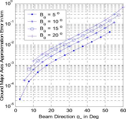
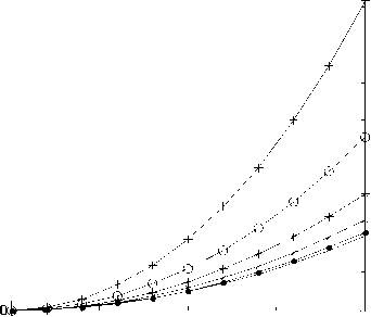
Figure 5-a: Absolute error variation with beam direction at different beamwidths.
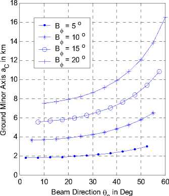
Figure 6-b: aC variation with beam direction at different beamwidths.
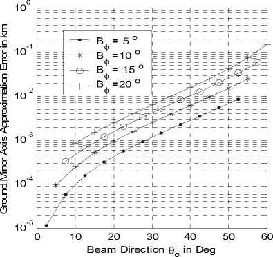
Fig 7-a: Absolute error variation with beam direction at different beamwidths.
Е 20
Ё

Е е -10
Cellular layout at 10 degrees beamwidth antennas ь -20
-30
Distance from subplatform point in km
-30 -20 -10 0 10 20 30
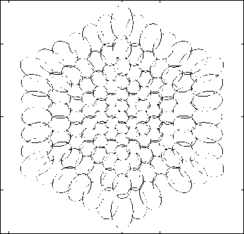
Figure 9: Cellular layout originating from HAP at 20 km high by 127 spot-beam antennas of 10 degrees beamwidth.
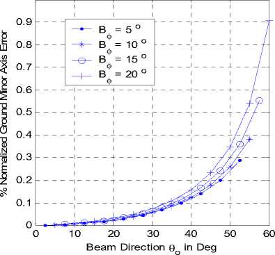
Fig 7-b: Relative error variation with beam direction at different beamwidths.
The design curves shown in Fig. 8 accomplish this task where the desired cell area can be determined at certain beam direction and beamwidth which is of major parameter in antenna design.
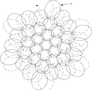
Extending the cellular layout to cover the whole required area in a frequency reuse fashion is shown in Fig. 9, where a fixed spot beam antennas of beamwidth 10 degrees are used to layout 127 cells covering a whole area of radius 30 km approximately and the HAP height is 20 km. The distance between the neighboring cells is calculated as in [15] where the coverage overlap between cells is optimized. One notice for this cellular structure is that the cells will be flattened when going outward due to the beam projection at lower elevation angles and this is acceptable because the user density also is always decreasing at the cell edges rather than at the center.
-
III. Modeling Of Hap Axial Yaw-Shift
The beam actually has two extreme elevation angles according to its direction. The significant one is the smaller. A user within a cell will be covered between such two elevation angles. The geometry is shown in Fig. 10 where we take the elevation plane ocd, defining the lower elevation angle as α and the upper one as β .
The upper elevation angle β is given by
Е го
θ o = 0
—•— θo = 10
—х— θ o = 20
θ o = 30
θ o = 40
—I— θo = 50
Antenna Beamwidth in degrees
Figure 8: Variation of cell area with the spot-beam antenna beamwidth located on a HAP at 20 km high and at different boresight angles.
β = 90 - θ - B θ o 2
and α is given by
α = 90 - θ - B θ o 2
The two elevation angles are equal when the platform
θ is overhead (i.e. θo = 0 o).
The major challenging factors in the platform communications arise from the positional and attitude instabilities. These problems result mainly from the wind forces and the atmospheric pressure variations at the HAP altitudes. These will force the platform to move from its specified position and results in variations in the cellular radio coverage configurations. These motions include the shift in altitude, horizontal and yaw-shifts due to the
temporarily change in wind direction. We concentrate here on the yaw-shift investigating the main resulted problems.
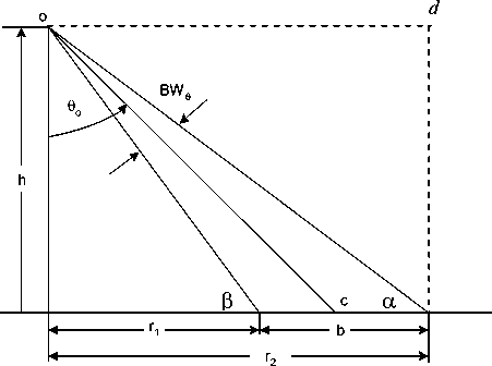
Fig. 10. Definition of cell elevation angles a and p
Firstly, we formulate an expression for the cell boundary motion due to this specific shift. This motion can be expressed as the distance the cell boundary moves , A c
( ), which depends on the elevation angle. As shown in Fig. 11, it may be written as rotates. The most affected cells by such angular error are that at the outer tier and all cells within the same tier (i.e.
those that have the same value of o ) will exhibit the same shift in angular distance.
-
IV. Impact Of Yaw-Shift On Handover
As depicted in Fig. 12, even a small rotation will greatly affect the system performance especially the handover process. Users at the cell boundaries will be more affected by such instability and may be subjected to frequent handovers. The problem at the outer tier cells is more serious than at the inner ones. This handover is triggered only by the platform instability and there is another user mobility initiated handover, which results from user motion toward another neighboring cell. Therefore, the total handover is estimated as:
HAP Total Handover = User Initiated Handover +
Instability Initiated Handover (22)
The instability-initiated handover is configured as the users that are handed to another cell and those users, which are handed from another neighboring cells.
A c = h tan ( 9 ) A ^ (20)
where Аф is the spin error angle (rotational error angle).
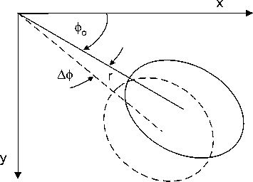
Fig. 11. Rotation of a HAP station and its effect on the radio coverage
For any given cell that has a lower and upper elevation angles (a and в respectively), this shift in a cell boundary is bounded by h cot an (в )ф < A c < h cot an (a )Аф (21)
As depicted from the last equation, this quantity differs as the elevation angle changes and the lower the elevation angle the larger is that distance. This moving cell has a great impact on the handover and location updating rates as will be discussed in the next subsection. Except the central cell (i.e. the cell where the platform is overhead), all other cells will exhibit such shift when the platform
-15
Shifted Pattern
Original Pattern
-5
-10
-5
Fig. 12. Effect of rotation by 10o of the HAP station located 20 km high on the cellular radio coverage
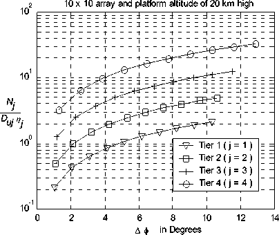
Fig.
13. The normalized number of handoff users as a function of the rotation angle (
Аф in Deg.) for different tiers.
Assuming that the user density is characterized in each tier of cells and these users are uniformly distributed within that tier, the platform is rotated by Аф, therefore the resulted number of handoff calls will be a function of the number of active calling users, the platform rotation shift (Аф), the cell area, and the elevation angles of such th tier. Assume that a j tier can accommodate certain number of the cells (footprints) denoted by M j , has a user
, „ D , n n ■ - , density of uj where a ratio of j of them are active and
rr has an inner and outer radii 1 j and 2 j determined by a в the elevation angles j and j respictively, then the number of users that undergoes instability handover for N that tier, j , can be written as
N j = n ( r j - r ) D — (23)
П
I M or
N, = ^ D Duj h 2 ■ -M ( cotan2 ( a, ) - cotan2 в , )) j 2 uj jj j j
If there are T tiers in the system, the total instability
N handoff users, T , will be
T
N t = 2 N , j = 1
Beside these assumptions we must include another population mapping factor that signifies the user distribution profile within the tier which may be characterized by tier terrain features, users grouping, trading centers, highways…etc. Denoting that factor by ° j , so the final number of instability initiated handovers of a tier will be
Nj = p Duj h2 Пj °j (cotan2 (a,)- cotan2 (ej)) (26) where the mentioned parameters in (26) are for such tier. A major problem occurs when the rotation angle reaches the azimuth beamwidth (Вф), at which all the cell users perform handover and consequently all the users in the corresponding tier will do that. In addition, the other tiers will be subjected to handovers depending on the corresponding cells beamwidths. A multiple handover will occur if the platform rotates by an angle which is a multiple of the azimuth beamwidth. A useful study of (26) is obtained if we consider the variation of N with the rotation angle Аф. We first determine the number of cells formed in each tier and the directions of beams forming these cells. In Fig. 13 we normalized N with Du n and we also assume uniform user distribution within the tiers (i.e. °j = 1). As clear from this figure, the number of instability initiated handover users increases as the rotation error angle increases, and also with the decrease in cell elevation angles. The impact of this issue is very important on the system performance. The system complexity increases as one expects such error occurrence at any time and if not managed as required it may cause system failure due to the expected large number of forced terminated calls.
-
V. Conclusion
Although HAP is considered as a new emerging technology for mobile communications that introduces many advantages compared to both terrestrial and satellite systems, it has potential problems due to positional instabilities that affect greatly the system performance. At their altitudes, a station keeping operation is needed which is done by continuous monitoring the platform attitude. The needed coverage stability is the main factor affecting the platform operations especially the handover process. On of the major drift problems for HAP is the rotationl motion due to wind changes. An analysis concerning the effect of yaw-shift on the number of handover calls is performed and an expression for this number is deduced indicating the main parameters controlling it. The analysis has shown that the angular shift even if small becomes more serious when moving to the outer cells as the number of handoff calls increases.
References Handover Analysis for Yaw-Shifted High-Altitude Platforms
- F. N. Pavlidou, M. Ruggieri, M. Gerla, R. Miura, "Communications via High Altitude Platforms: Technologies and Trials", International Journal of Wireless Information Networks, Vol. 13, No. 1, pp 1-4, January 2006.
- A. Mohammed, S. Arnon, D. Grace, M. Mondin and R. Muira, "Advanced Communication Techniques and Applications for High Altitude Platforms", EURASIP International Journal of Communications and Networking, 2008. Editorial to the special issue.
- S. Karapantazis and F. N. Pavlidou, "The role of high altitude platforms in beyond 3G networks", IEEE Wireless Communications Magazine, Vol. 12, No. 6, pp. 33-41, 2005.
- A. Mohammed, A. Mehmood, F. N. Pavlidou and M. Mohorcic, "The Role of High-Altitude Platforms (HAPs) in the Wireless Global Connectivity", Proceedings of the IEEE, Vol. 99, No. 11, pp. 1939 – 1953, Nov. 2011.
- J. Kim, D. Lee, J. Ahn, D. S. Ahn and B. J. Ku, "Is HAPS Viable for the Next-Generation Telecommunication Platforms in Koria", EURASIP Journal on Wireless Communications and Networking, Vol. 2008, doi: 1155/2008/596383, 2008.
- P. Pace and G. Aloi, "Disaster Monitoring and Mitigation using Aerospace Technologies and Integrated Telecommunication Networks", IEEE Aerospace and Electronic Systems Magazine, Vol. 23, No. 4, pp. 3-9, April 2008.
- J. Thornton, D.A.J. Pearce, D. Grace, M. Oodo, K. Katzis and T.C. Tozer, "Effect of Antenna Beam Pattern and Layout on Cellular Performance in High Altitude Platform Communications", Wireless Personal Communications, Vol. 35, pp. 35-51, 2005.
- Yasser Albagory Moawad Dessouky, Hamdy Sharshar, "Geometrical Analysis of High Altitude Platforms Cellular Footprint," Progress In Electromagnetics Research, PIER 67, pp. 263-274, 2007.
- M. Dessouky, H. Sharshar and Y. Albagory, "Design of high altitude platforms cellular communications", Progress In Electromagnetics Research, Vol 67, pp. 251-261, 2007.
- M. Dessouky, H. Sharshar, Y. Albagory, "Improving The Cellular Coverage from A High Altitude Platform by Novel Tapered Beamforming Technique", Journal of Electromagnetic Waves and Applications, JEMWA, Vol.21, No.13, pp. 1721 –1731, 2007.
- Yasser Albagory, "A Novel Design of Arbitrary Shaped Cells for Efficient Coverage from High Altitude Platforms", Progress In Electromagnetics Research Letters, Vol. 1, 245-254, 2008.
- L. Boccia, P. Pace, G. Amendola, G. D. Massa, "Low Multipath Antennas for GNSS-based Attitude determination Systems Applied to High Altitude Platforms", GPS Solutions, Vol. 12, No. 3, pp. 163-171, July 2008.
- Yasser Albagory, "Sectorized Hamming Concentric Circular Arrays for Stratospheric Platforms Cellular Design", International Journal of Computer Network and Information Security, Vol. 5 No. 9, pp. 21-27, 2013.
- M. Nofal, S. Aljahdali and Y. Albagory, "Tapered Beamforming for Concentric Ring Arrays", AEU International Journal of Electronics and Communications, Vol. 67, No. 1, pp. 58-63, 2013.
- Sultan Aljahdali, Mostafa Nofal and Yasser Albagory, "Geometrical Correction for Cell Deployment in Stratospheric Cellular Systems", Progress In Electromagnetics Research C, Vol. 29, pp. 83-96, 2012.
