Harmonics and neutral line current compensation in three-phase four-wire power systems

Author: Chernyshov Maxim O., Dovgun Valery P., Vazhenina Irina G., Temerbaev Sergei A., Novikov Victor V.
Journal: Журнал Сибирского федерального университета. Серия: Техника и технологии @technologies-sfu
Article in issue: 5 т.11, 2018.
Free access
Load unbalance and modern office equipment result in a significant neutral current in three-phase four-wire low-voltage power systems. This paper considers a new configuration of hybrid power filter for power quality management in three-phase four-wire low voltage power systems. The proposed hybrid filter is composed of a single-phase power converter and a three-phase passive filter connected in series. The hybrid filter can be operated in both passive and hybrid mode. The compensating performance of the filter is confirmed with computer simulation using MATLAB software. Analysis and simulation proved that the hybrid filter is an effective solution for neutral current mitigation.
Three-phase four-wire power system, hybrid power filter, neutral line current
Short address: https://sciup.org/146279535
IDR: 146279535 | UDC: 621.300 | DOI: 10.17516/1999-494X-0053
Компенсация высших гармоник и токов нейтральных проводников в трехфазных четырехпроводных сетях
Современное офисное оборудование и несимметрия нагрузок являются основной причиной увеличения токов нейтральных проводников в трехфазных четырехпроводных сетях низкого напряжения. В статье рассмотрена новая конфигурация силового гибридного фильтра для управления качеством электроэнергии в трехфазных четырехпроводных сетях. Предложенный гибридный фильтр образован последовательным соединением трехфазного пассивного фильтра, настроенного на частоту доминирующей третьей гармоники, и однофазного инвертора. Фильтр может работать как в пассивном, так и в гибридном режиме. Компенсационные характеристики предложенного фильтра проанализированы с помощью моделирования в MATLAB. Анализ показал, что предложенный гибридный фильтр является эффективным средством ослабления гармоник и токов нейтральных проводников.
Text of the scientific article Harmonics and neutral line current compensation in three-phase four-wire power systems
Fig. 1. The system configuration of the hybrid filter for neutral current harmonics mitigation converter acts as an acti significantly reduced because major part of t The hybrid filter can operate in either passiv verter, CB – control block.
Computation of th by the digital two-band frequency-dividi tude characteristics. The output voltage of s of the neutral-line current IN :
и -R i^+R (D uA (1)
where z’y and iN ) are fundamental and harmonic components of the neutral current, respectively; R AF 1 and R AFh are transfer resistances of the active fil r on the fundamental and harmonics frequencies. The output signals of the two-band filter are amplified and sent to the PWM circuit as the modulation signal.
The current flowing through the neutral conductor is only the zero sequence component. The zero-sequence equivalent circuit of hree-phase four-wire distribution power system with the proposed hybrid filter is shown in Fig. 2, where V S 0 is a zero-sequence voltage source modeling the
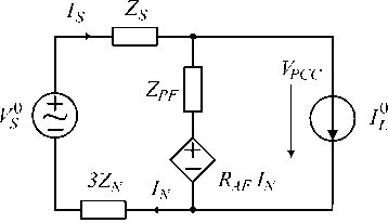
Fig. 2. The zero-sequence equivalent circuit of the distribution power system unbalanced utility voltage or nonsymmetr linear load, IL0 is the zero- sequence current source caused by the nonlinear load. ZS and ZN are the phase-line impedance and neutral-line impedance of the distribution system, respect vely. ZPF is the impedance of the passive filter. Active power filter is considered as a current controlled voltage source with output voltage according to the formula (1).
According to Fig. 2 the neutral-line current I N can be derived as
I
U nN ZN
3 V S 0 3 Z PF I L 0
Zs + Zpf + 3(Zn + Raf)+ Zs + Zpf + 3(Zn + Raf) .
Voltage in the point of common coupling (PCC)
_ ( Z pf + 3 R af ) V 0
VPCC " Zs + Zpf + 3(Zn + Raf ) +
ZPF ( ZS + 3 R AF ) I L
Zs + Zpf + 3(Zn + Raf ) .
Equations (2, 3) may be applied for the analysis of compensating characteristics of the hybrid filter for zero-sequence components. As seen in (2, 3), operation of the active power filter is equivalent to inserting a resistor R AF in series with neutral-line impedance of the distribution system. Hence, harmonics of the neutral-line current and the voltage VPCC can be suppressed more effectively.
Calculation Of The Compensating Signal
Control strategies to generate compensating signals for active filters are based on the frequencydomain or time-domain techniques [9, 10]. Control strategy in the frequency domain is based on the Fourier analysis of the distorted current or voltage. The high-order harmonic components are separated from distorted signals and combined to form compensating commands. But the discrete Fourier transform (DFT) loses accuracy in nonstationary situations. Commonly used calculation methods in the time domain are the instantaneous reactive (P-Q) theory approach, neural network theory, notch filter approach, adaptive signal processing. Most of these algorithms have a much better dynamic response than the DFT. In this paper computation of the compensation signal is performed by the two-band infinite impulse response (IIR) filter (Fig. 3). It realizes two double-complementary transfer functions:
F( )_ En(z)_ 1 [1 + A( )]
1 X ( z ) 2 ,
E. (z)
F 2 ( z )=i X i z y=2[ 1 - A ( z ) ] , (5)
where A ( z ) is a second-order all-pass transfer function. F ( z ) is a notch-type transfer function and F ( z ) is a bandpass-type transfer function tuned to the fundamental frequency ω0.
A ladder-form realization of all-pass IIR digital filter is shown in Fig. 4. In Fig. 4 x(n) and y(n) are input and output signals, respectively. Transfer function of the ladder all-pass filter is the following:
A(. z ) =
Y ( z ) _ z 2 + k 1 ( 1 + k 2 ) z 1 + k 2 X ( z ) k 2 z -2 + k i ( 1 + k 2 ) z -1 + 1.
X ( z )
* A ( z)
Y ( z )
E n ( Z ) -►
E bp ( z )
Fig. 3. Two-band IIR filter
The polynomials of nominator and denominator of equation (6) have mirror symmetry. Ladder IIR filter (Fig. 4) realizes all-pass transfer function module of which is equal to 1 in the all frequency range. According to (4, 5), transfer functions of the two-band IIR filter, shown in Fig. 3, are the following:
F 1 ( z ) = 1 ( z
2 k 2 z
. -2
+ 2 k z + 1 ) ( 1 + k 7) 2 + k 1 ( 1 + k 2 ) Z -1 + 1 ,
F2 (- ) =
1 — 21 - k 2 ) ( 2 - 1 ) 1
2 k T z 2 + k 1 ( 1 + k T ) z 1 + 1
where k is the adaptive coefficient, which should converge to – cosω for reject a sinusoid with frequency ω0. Suppression frequency of the notch filter can be modified by k 1 and stopband width by k 2.
The all-pass IIR filter in Fig. 4 is adapted using adaptive algorithms related to the lattice finite impulse response (FIR) filters. The lattice structure of second-order FIR filter is shown in Fig. 5. Adaptation algorithm of the FIR lattice was considered in [11].
MATLAB-based modeling of the proposed filter
Traditionally, nonlinear loads are represented as current sources. However, single-phase diode rectifiers in most cases have capacitive smoothing filters. This type of nonlinear load is equivalent to a
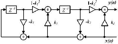
Fig. 4. Ladder structure of second-order all-pass IIR filter
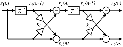
Fig. 5. Second-order FIR lattice filter voltage source with small impedance [2, 12]. Common shunt passive and active filters have been shown in [12] to have different compensation characteristics for current-source nonlinear loads and voltagesource nonlinear loads. In this section we consider compensation characteristics of the proposed filter for different rectifier loads.
Case A: diode rectifier has the RLC load. The MATLAB model of the distribution power system, hybrid filter and the load is shown in Fig. 6. The nonlinear load consists of three single-phase diode rectifiers with a LC smoothing filters. Each rectifier is connected between line and neutral point. The linear load is modeled by the series RL network in each phase. Parameters used in the computer simulation are shown in Table I.
Fig. 7 shows the simulation results for the neutral current in the case of applying the passive filter and the hybrid filter. The passive filter is connected in 0,2s. The filter works in the passive mode until 0,4s when the power convertor starts. As seen in Fig. 7, the neutral current is attenuated from 30 A to less than 5.3 A (RMS).
The harmonic content of the neutral current is shown in Fig. 8. The total harmonic distortion (THD) of the PCC voltage is less than 4%.
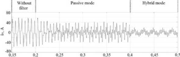
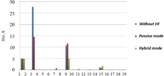
Fig. 9, 10 show the simulation results for the unbalanced RLC load. In this case the neutral current contains both triplen and fundamental harmonics. Active power filter does not influence over neutralline fundamental harmonic.
Table 1. Model parameters used in the simulation (RLC load)
|
Parameter |
Value |
|
R S , L S |
0,1 Ω, 318 µH |
|
R N |
0,1 Ω |
|
R L , L L , C L |
40 Ω, 1.2 mH, 530 µF |
|
RLL, LLL |
15 Ω, 47.7 mH |
|
V S |
220 V, 50 Hz |
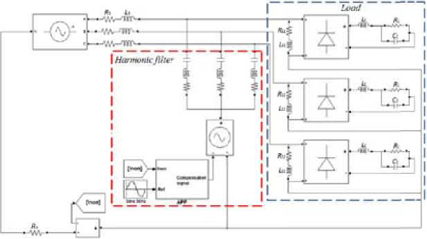
Fig. 6. The MATLAB model of the hybrid filter and the distribution power system (RLC load)
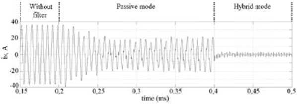
Fig. 7. Waveform of the neutral line current I N (balanced RLC load)
• Without HF
• Passive mode и Hybrid mode
Fig. 8. Spectrum of the neutral line current I N (balanced RLC load)

Fig. 9. Waveform of the neutral line current I N (unbalanced RLC load)
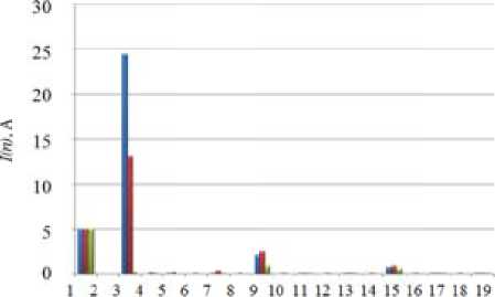
• Without HF
• Passive mode
- Hybrid mode
Case B: diode rectifiers have the RC load. The MATLAB model of the load, hybrid filter and the distribution power system is shown in Fig. 11. The nonlinear load consists of three single-phase diode rectifiers with a load of capacitor and resistor connected in parallel. The parameters used in the computer simulation are shown in Table 2.
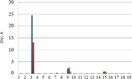
The simulation results for the neutral current in the case of the balanced RC load are shown in Fig. 12. The neutral current is attenuated from 25 A to less than 3 A (RMS). The harmonic content of the neutral current is reported in Fig. 13. In this case the THD of the voltage in the PCC is less than 2.5 %.
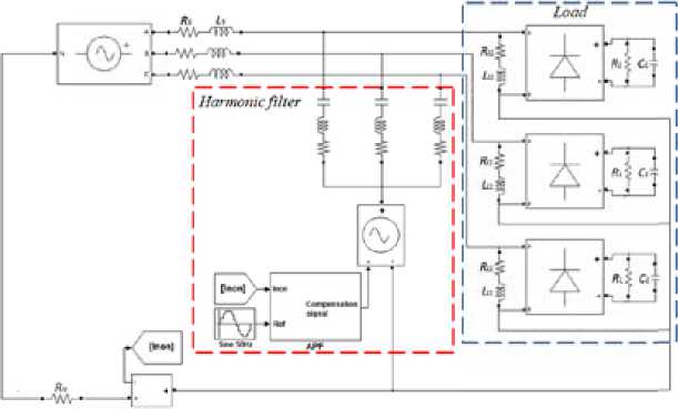
Fig. 11. The MATLAB model of the hybrid filter and the distribution power system (RC load)
Table 2. Model parameters used in the simulation (RC load)
|
Parameter |
Value |
|
RS, LS |
0,1 W, 318 µH |
|
R N |
0,1 Ω |
|
R L , L L , C L |
40 Ω, 937.5 µF |
|
RLL, LLL |
15 Ω, 47.7 mH |
|
V |
220 V, 50 Hz |
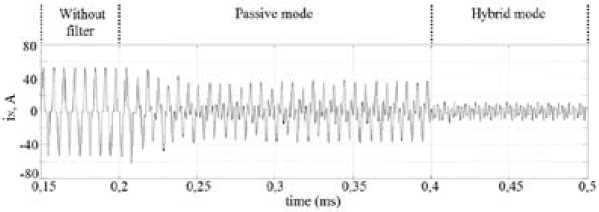
Fig. 12. Waveform of the neutral line current I N (balanced RC load)
The simulation results for the neutral current for the unbalanced RC load are shown in Fig. 14. The harmonic content of the neutral current is reported in Fig. 15.
Simulation results verify that the proposed hybrid filter is able to compensate for harmonic neutral currents in cases when nonlinear load has characteristics of current source or voltage source.
Conclusion
The overload of the neutral conductor is becoming a serious problem in modern three-phase four wire distribution low voltage power systems. In this paper, a hybrid filter is proposed to compensate
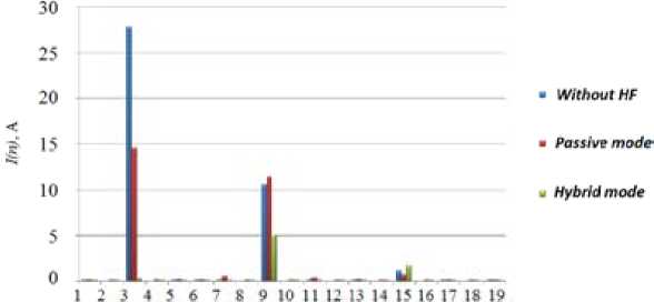
Fig. 13. Spectrum of the neutral line current I N (balanced RC load)
time (пи)
Fig. 14. Waveform of the neutral line current I N (unbalanced RC load)
harmonics and neutral current in three-phase four-wire distribution power systems. The proposed filter is composed of a three-phase passive filter and a single-phase power converter connected in series. The output voltage of the active filter is proportional to harmonic components of the neutral-line current.
The simulation results verify that the proposed filter demonstrates good compensation characteristics for different nonlinear loads. It can provide a better neutral current mitigation than the passive filter.
References Harmonics and neutral line current compensation in three-phase four-wire power systems
- Key T., Lai J.-S. Analysis of harmonic mitigation methods for building wiring systems, IEEE transactions on power systems, 1998, 13(3), 890-897.
- Pomilio J., Deckmann S. Characterization and compensation of harmonics and reactive power of residential and commercial loads, IEEE transactions on power delivery, 2007, 22(2), 10491055.
- Gruzs T.M. A survey of neutral currents in three-phase computer power systems, IEEE Trans. on Industry Application, 1990, 26(4), 719-725.
- Jou H.L., Wu J.C., Wu K.D., Chiang W.J., Chen Y.H. Analysis of zig-zag transformer applying in the three-phase four-wire distribution power system, IEEE transactions on power delivery, 2005, 20(2), 1168-1178.
- Choi S., Jang M. A reduced-rating hybrid filter to suppress neutral current harmonics in three-phase four-wire systems, IEEE transactions on industrial electronics, 2004, 51(4), 927-930.
- Vodyakho O., Mi C. Three-level inverter-based shunt active power filter in three-phase three-wire and four-wire systems, IEEE transactions on power electronics, 2009, 24(5), 1350-1363.
- Aredes M., Hafner J., and Heumann K. Three-phase four-wire shunt active filter control strategies, IEEE transactions on power electronics, 1997, 12(2), 311-318.
- Wu J.-C., Jou H.-L., Hsiao H.-H., Xiao S.-T. A new hybrid power conditioner for suppressing harmonics and neutral-line current in three-phase four-wire distribution power systems, IEEE transactions on power delivery, 2014, 29(4), 1525-1532.
- Akagi H. Active harmonic filters, Proceedings of the IEEE, 2005, 93(12), 2128-2141.
- Cirrincione M., Pucci M., Vitale G., Miraoui A. Current harmonic compensation by a single-phase shunt active power filter controlled by adaptive neural filtering, IEEE trans. on Industrial Electronics, 2009, 56(8), 3128-3143.
- Temerbaev S., Dovgun V. Improvement of Power Quality in Distributed Generation Systems Using Hybrid Power Filters, in Proc. Harmonics and Quality of Power, ICHQP, 2014, 694-698.
- Peng F. Harmonic sources and filtering approaches, IEEE industry application magazine, 2011, 7(4), 18-25.
