High-Altitude Platforms Cellular System for Sparsely Populated Areas

Author: Yasser Albagory, Fahad Al Raddady
Journal: International Journal of Computer Network and Information Security(IJCNIS) @ijcnis
Article in issue: 4 vol.6, 2014.
Free access
In this paper, the cellular communications using high altitude platform (HAP) will be discussed including the coverage analysis and design. The cells are analyzed showing the main parameters affecting its shape, layout and area which are important in the cellular design stage. This HAP cellular system is very important to cross the gap of difficult extension of ground infrastructure especially for sparsely populated areas needing communications services. The system design is explained where the footprint of the HAP cell is demonstrated and the overall cellular layout is established. As a case study, the coverage of the HAP cellular system is proved to cover some areas in the Kingdom of Saudi Arabia (KSA) using several scenarios such as populated as well as long highways passing through desert areas. The HAP cells are generated using spot-beam antennas which are practically candidate. The simulation results show that a single HAP can provide hundreds of microcells for urban areas while covering very long highways that can extend to several hundreds of kilometers which is very useful in covering the long highways linking sparsely separated cities in KSA.
Cellular Communications, High altitude platforms, directional antennas, phased antenna arrays
Short address: https://sciup.org/15011290
IDR: 15011290
Text of the scientific article High-Altitude Platforms Cellular System for Sparsely Populated Areas
High altitude platform (HAP) has been developed using an airship positioned at a predetermined altitude approximately 17-22 km high in the stratospheric layer where it can be used for telecommunications, broadcasting and environmental measurements [1-6]. The application of HAPs for mobile communications is very important and economical as it collects the advantages of using satellites but at lower altitudes which means both lower propagation delay and lower path loss. On the other hand the terrestrial system suffers from propagation problems due to multipath scenario and can be reduced mostly using HAPs. In the terrestrial cellular systems, the geometry of the formed cells can be determined by considering its hexagonal shape and it is easy to find the other cells locations, but in the case of using HAPs, the cell will be defined by the half power contour on the ground which can be considered as an ellipse. In dealing with the footprint of HAPs, the cell parameters must be determined such as the major and minor axes and their variations with the utilized antenna beam widths and beam direction. In [7], the coverage of the HAP cell is well defined based on an assumption that the platform height is much smaller than the earth radius giving approximate figures for the cell dimensions especially at lower altitudes, while in [8], the HAP cell is determined by including the earth surface curvature and the cell parameters are determined with more complicated equations including the earth parameters itself. The HAP coverage area can extend to several hundreds of kilometers which is one of the main advantages of using it in cellular mobile communications and make it very feasible for covering largely and sparsely populated areas such as in the KSA and neighboring countries. Therefore, in this paper, the HAP cellular system is designed to cover this type of developed regions which cross the gap of extending the infrastructure over desert and difficult geographical areas. The HAP cellular system is reviewed and analyzed and the design equations relating the teletraffic information to the HAP antenna parameters are deduced. Several cellular system designs are also introduced including main cities, highways, desert and sparsely populated areas and new developing areas.
The paper is arranged as follows, in section II; the power gain contours of the HAP cells are analyzed. Section III presents the HAP cellular system built using fixed spot-beam antennas structure. Section IV describes the design of HAP cellular system for several cell scenarios and finally section V concludes the papers.
II HAP CELLULAR LAYOUT ANALYSIS
The HAPs wireless communication system utilizes the directional, as well as phased antenna arrays to construct its ground cells [9-13]. Directional antennas may be in the form of parabolic reflectors, horn antennas, lens antennas which give the desired directional pattern. The use of directional antennas has some advantages such as its practical availability and simplicity but on the other hand a failure in one of them results in a coverage hole due to the absence of the beam used in forming its cell. Ground cells also can be formed by directing a beam using phased arrays which has a widespread use [14] where the coverage beam is formed by a number of antenna elements therefore any element failure in the array will slightly distort the beam pattern (the beam will have slightly larger beam widths) and this can be an advantage compared with the use of directional antennas. In this paper, we use the spot-beam antennas to form the ground cells as it is feasibly realizable and available for many applications and provide less complexity to the system.
bF = h
( ( B„ A tan 9 + — - tan 9
oo
V V 2 ) V
B θ
where the subscript F stands for flat ground approximation and h is the platform altitude in km.
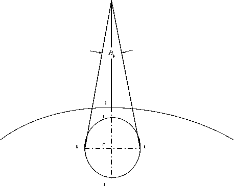
Figure 1: HAP cell footprint
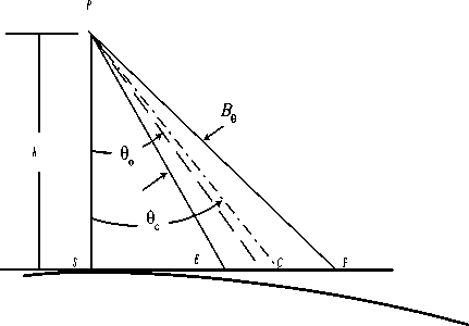
Figure 2: Flat ground approximation geometry
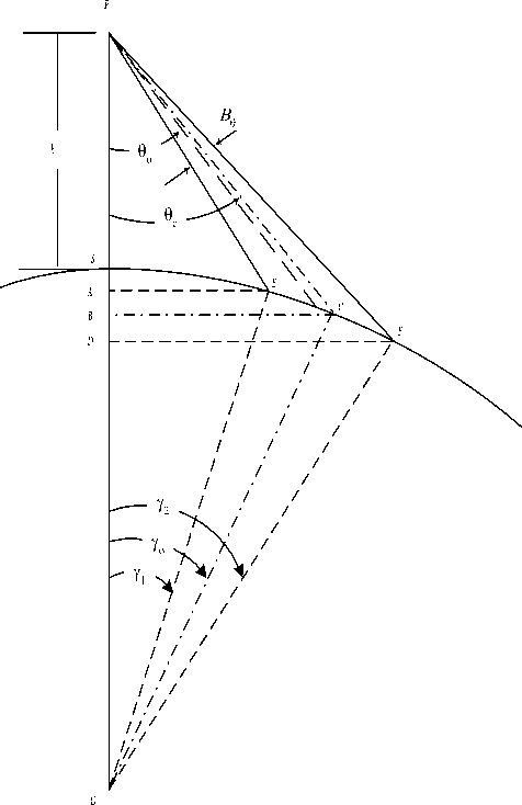
Figure 3: Curved earth coverage geometry
The HAP is located at an altitude about 20 km high, which is very small compared with the earth’s radius, we can approximate the earth as a flat surface as shown in Fig. 1. In this figure, the footprint of a beam formed by any of the mentioned antennas onboard the HAP is shown. The cell as depicted in Fig. 2 is defined by the coverage beam that has a direction of o and cross BB section beamwidth of B9 and ф, and the projection of the beam on the ground will be an ellipse that has a major axis EF and minor axis HK . Denoting the distance EF as bF which is given by
The cell center point, C, is located by an angle from the platform given by
9 c = tan 1
tan | 9 - — | + —
V o 2 ) 2 h
and the cell minor axis distance HK can be denoted as aF and can be given by aF = 2 h sec (9c) tan
( B £
These two quantities (i.e. the minor and major axes) will define the cell shape and this assumption can be used for smaller and moderate coverage areas but when the coverage area increases the approximation error will increase and can’t be longer used and instead we apply the curved-earth cellular model where we take into consideration the earth curvature. A side view is shown in Fig. 3, which depicts the geometry used to define the cell parameters. In this figure, the major axis will be the arc between the two ground central angles Y 1 and Y 2 which can be deduced as
and in this case the value of 0 c will be
9 c = tan 1

or
9 c = tan 1
• -if I, . h 1 C Y, = sin 1 1l +— |sin| 0„
1 H RJ I °
0 11-0 + -^ (4)
2 JJ ° 2
And
Therefore the cell minor axis, a C , will be
Y2 = sin ’1 ! 11 + - | sinf 0 + -
2 К R J I ° 2
o
- 0
aC
= HK = 2 PC tan
(B 1
^
к2 J
where the cell center has a ground center angle given by or
Y° = 2 (Y1 + /2)
ac = 2 h sec ( 9 ) tan —
к 2 J
and we can get the distance PB as:
P- = h + R f 1 - 2 ( cos(y1) + R cos(y2) ) J
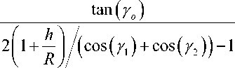
and the distance BC will be
-C = 2 R ( cos(Y 1 ) + R cos(Y 2 ) ) tan ( Y ° )
which can be also given by
aC = 2 R tan
(- If, IT | к 2 Jк
1 h 1Z z z xx12 1+--T(co s ( Y 1 ) + cos( Y 2 )) |
R 2 J
1 1 1/2
+ 4 (cos( Y 1 ) + cos( Y 2 )) 2 tan2 ( Y ° ) J
therefore the platform-to-cell center slant distance will be
PC = V P-2 + -C2
from the above equations, the cell major axis, b C , can be defined as
be = EF = R ( y2 - Y1) (10)
or
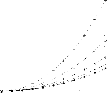
The cells described by (11) and (16) are more accurate than those given in (1) and (2) especially at lower elevation angles. Fig. 4-a and b depict the variations of the cell major axes with the beam direction 0 -„
° at different beam widths 0 for both coverage models using directional antennas. The variations in this figure indicate the increase in the footprint with increasing both the beam direction and the beamwidth. The difference (or the absolute distance error) between the two quantities in km is shown in Fig. 5-a while the relative error in the cell major axis between the two models may be defined as:
bC = R
f , sin-1
к
ffi - 1 . f -6 11
1 + — sin 9 + —
o к к R J к 2 J J
P,
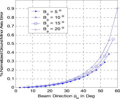
b — b bC—bF- x1QQ % bC
- sin
fit h 1 . fa
1 + — sin 9
o к к R J к
-
- 9
J
J
- -9
J
where its variation with both the beam direction and beamwidth is shown In Fig. 5-b. In this figure, the error
may approach about 2 % of the major axis for beamwidth of 20 o at a beam direction of about 60 o which corresponds to 700 meter difference. This large difference between the two expected major axis values for the two models will affect the system design especially for the cells at the coverage border or edges. On the other hand, the error is much smaller for the inner coverage cells and for cells of narrower beamwidth. For example a beamwidth of 5 o generates cells that have an error not exceeding 12 meters for direction no more than 40 o as depicted in Fig. 5-a. The same analysis is done for the cell minor axis as depicted in Fig. 6-a and b and the error (absolute and relative) for the two models is shown respectively in Fig. 7-a and b.
One can therefore utilize the simple equations used in the flat ground model for the range of moderate and acceptable error (such as for cells near the coverage center) while for larger error we can utilize the better curved earth model thus optimizing the use of both models.
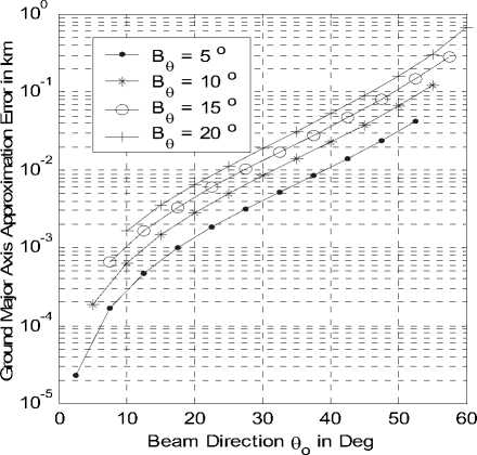
Figure 5-a: Absolute error variation with beam direction at different beamwidths.
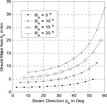
Figure 4-a: bF variation with beam direction at different beamwidths.
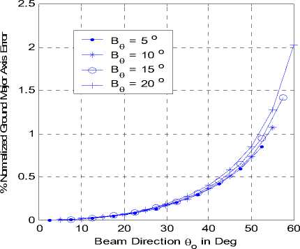
Figure 5-b: Relative error variation with beam direction at different beamwidths.
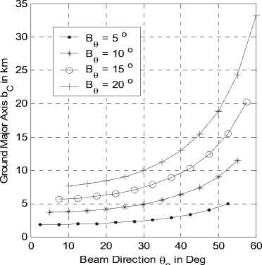
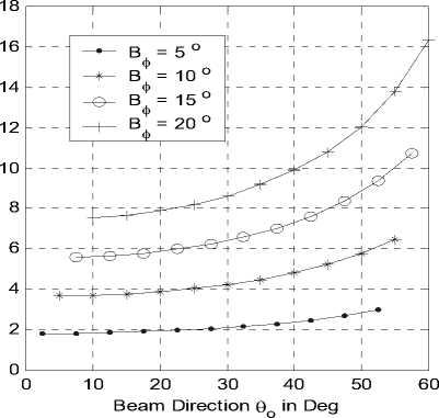
Figure 6-a: a F variation with beam direction at different beamwidths.
Figure 4-b: b C variation with beam direction at different beamwidths.
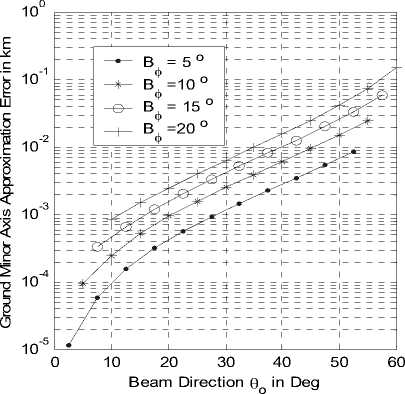
Figure 7-a: Absolute error variation with beam direction at different beamwidths.
system topology which resembles the star topology in networks. This means that the system is centralized and all the cells are originating from the same point. The design stage includes some teletraffic information that should be linked with the available communication resources to establish the desired cellular system. We have a certain number of communication channels, a grade of service in terms of call blocking probability and call parameters such as the call holding time and call rate per user. The relation between blocking probability, offered traffic and number of channels is given by the following formula:
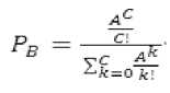
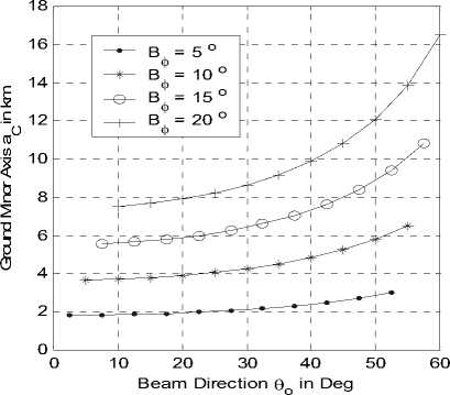
Figure 6-b: a C variation with beam direction at different beamwidths.
Where р= is the blocking probability, A is the total offered traffic and C is the number of channels per cell. The total offered traffic is given by the following simple relation:
Л — N^Ay
Where ^ is the number of users in the cell and Au is the offered traffic per user which is given by:
^^ — А, н (19)
Where 1. is the call rate and н is the channel holding time.According to the values of R and C we can determine the value of the total offered traffic. In addition, the call rate per user and the channel holding time determine the offered load per user and consequently we can determine the number of users per cell form (18) which is very important parameters for determining the required cell area.
From the population density (i.e. the number of users per unit area) and the number of users per cell, we can determine the cell area from the following relation:
The cell area in (20) should be the same area determined by the HAP ellipsoidal cell given by:
Figure 7-b: Relative error variation with beam direction at different beamwidths.
III HAP CELLULAR LAYOUT PLANNING
The procedure of cellular design for HAPs is the same for terrestrial cellular mobile system except in the
The required cell area in (20) can be determined from the antenna beamwidths which give the major and minor axes that realize the required cell area in (21). To do this design task, we should find design curves that relate the cell axes to the cell area in (21).
The design curves shown in Fig. 8 accomplish this task where the desired cell area can be determined at
certain beam direction and beamwidth which is of major parameter in antenna design.
θ o = 0
---•-- θ o = 10
θ o = 20
—* θo = 30
—е θ o = 40
θ o = 50
Antenna Beamwidth in degrees
Figure 8: Variation of cell area with the spot-beam antenna beamwidth located on a HAP at 20 km high and at different boresight angles.
е 20
Е

Е
2 -10
Q -20
Cellular layout at 10 degrees beamwidth antennas
-30
Distance from subplatform point in km
-30 -20 -10 0 10 20 30
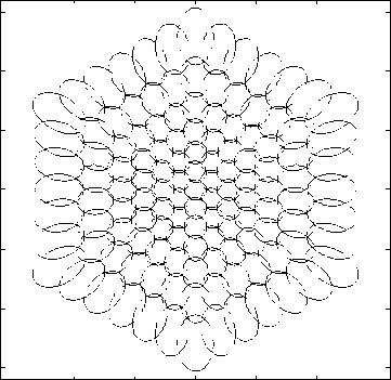
Figure 9: Cellular layout originating from HAP at 20 km high by 127 spot-beam antennas of 10 degrees beamwidth.
Extending the cellular layout to cover the whole required area in a frequency reuse fashion is shown in Fig. 9, where a fixed spot beam antennas of beamwidth 10 degrees are used to layout 127 cells covering a whole area of radius 30 km approximately and the HAP height is 20 km. The distance between the neighboring cells is calculated as in [15] where the coverage overlap between cells is optimized. One notice for this cellular structure is that the cells will be flattened when going outward due to the beam projection at lower elevation angles and this is acceptable because the user density also is always decreasing at the cell edges rather than at the center.
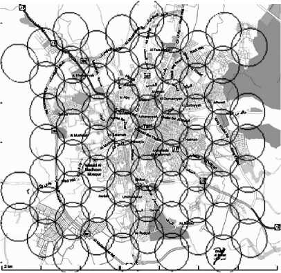
Figure 10: Cellular layout for covering most of Taif City in Saudi Arabia. The HAP is located in the center of the figure and the average cell area is 2.5 square km.
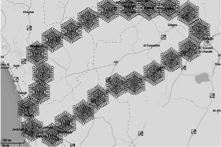
Figure 11: Extension of HAP cellular layout to cover very long highways and their surrounding regions using a network of HAPs. The coverage area per HAP extends to about 100 km diameter and the Riyadh-Mecca highway can be covered by only 10 HAPs.
As a case study, the HAP cellular layout can be now tailored to the coverage area and Fig. 10 displays one of the possible designs of a HAP covering Taif city in Saudi Arabia.
The city as shown in this figure has an approximate radius of 7 km and can be covered with 70 cell of an average area of 2.5 km2. The average cell radius is 1 km which represents a microcell that is suitable for providing the required higher user capacity in cellular systems.
The design can be generalized to cover wider areas including highways and small cities. In Fig. 11, the long highways such as that connecting Riyadh - Mecca via Taif and Riyadh - Medina are covered by a network of HAPs where each highway is covered by 10 HAPs and each is used to cover an area of 100 km diameter containing 127 cells. By the same procedure, we can cover the whole regional areas in KSA with even microcells or macrocells.
The feasibility of providing mobile communications using HAPs is the reduction in the required ground infrastructure, high security, large area coverage, low cost for installation of HAP network and better signal reception from HAPs.
V CONCLUSION
The emerging technology of HAPs provides many advantages and benefits for establishing better communications systems compared to the conventional terrestrial and satellite systems. In this paper, the HAP cellular layout has been analyzed showing the possible relations that controls those cells. The cell can be described by approximating the earth surface as flat and using simple equations especially at higher elevation angles. The other approximation takes into consideration the earth curvature property and deduced more accurate equations that can be used for lower elevation regions. The system design is described for mobile cellular communications and design curves are drawn to relate the real system parameters especially the antenna beamwidth and direction to the required cell area. As a case study, a HAP cellular system is designed to cover one of the KSA cities which is Taif city and another network of HAPs to cover long highways that extend to several hundreds of km.
References High-Altitude Platforms Cellular System for Sparsely Populated Areas
- F. N. Pavlidou, M. Ruggieri, M. Gerla, R. Miura, “Communications via High Altitude Platforms: Technologies and Trials”, International Journal of Wireless Information Networks, Vol. 13, No. 1, pp 1-4, January 2006.
- A. Mohammed, S. Arnon, D. Grace, M. Mondin and R. Muira, “Advanced Communication Techniques and Applications for High Altitude Platforms”, EURASIP International Journal of Communications and Networking, 2008. Editorial to the special issue.
- S. Karapantazis and F. N. Pavlidou, “The role of high altitude platforms in beyond 3G networks”, IEEE Wireless Communications Magazine, Vol. 12, No. 6, pp. 33-41, 2005.
- A. Mohammed, A. Mehmood, F. N. Pavlidou and M. Mohorcic, “The Role of High-Altitude Platforms (HAPs) in the Wireless Global Connectivity”, Proceedings of the IEEE, Vol. 99, No. 11, pp. 1939 – 1953, Nov. 2011.
- J. Kim, D. Lee, J. Ahn, D. S. Ahn and B. J. Ku, “Is HAPS Viable for the Next-Generation Telecommunication Platforms in Koria”, EURASIP Journal on Wireless Communications and Networking, Vol. 2008, doi: 1155/2008/596383, 2008.
- P. Pace and G. Aloi, “Disaster Monitoring and Mitigation using Aerospace Technologies and Integrated Telecommunication Networks”, IEEE Aerospace and Electronic Systems Magazine, Vol. 23, No. 4, pp. 3-9, April 2008.
- J. Thornton, D.A.J. Pearce, D. Grace, M. Oodo, K. Katzis and T.C. Tozer, “Effect of Antenna Beam Pattern and Layout on Cellular Performance in High Altitude Platform Communications”, Wireless Personal Communications, Vol. 35, pp. 35-51, 2005.
- Yasser Albagory Moawad Dessouky, Hamdy Sharshar, “Geometrical Analysis of High Altitude Platforms Cellular Footprint,” Progress In Electromagnetics Research, PIER 67, pp. 263-274, 2007.
- J. Thornton, “A Low Sidelobe Asymmetric Beam Antenna for High Altitude Platform Communications”, IEEE Microwave and Wireless Components Letters, Vol. 14, No. 2, pp. 59-61, February 2004.
- M. Dessouky, H. Sharshar, Y. Albagory, “Improving The Cellular Coverage from A High Altitude Platform by Novel Tapered Beamforming Technique”, Journal of Electromagnetic Waves and Applications, JEMWA, Vol.21, No.13, pp. 1721 –1731, 2007.
- Yasser Albagory, “A Novel Design of Arbitrary Shaped Cells for Efficient Coverage from High Altitude Platforms", Progress In Electromagnetics Research Letters, Vol. 1, 245-254, 2008.
- L. Boccia, P. Pace, G. Amendola, G. D. Massa, “Low Multipath Antennas for GNSS-based Attitude determination Systems Applied to High Altitude Platforms”, GPS Solutions, Vol. 12, No. 3, pp. 163-171, July 2008.
- Yasser Albagory, “Sectorized Hamming Concentric Circular Arrays for Stratospheric Platforms Cellular Design”, International Journal of Computer Network and Information Security, Vol. 5 No. 9, pp. 21-27, 2013.
- M. Nofal, S. Aljahdali and Y. Albagory, “Tapered Beamforming for Concentric Ring Arrays”, AEU International Journal of Electronics and Communications, Vol. 67, No. 1, pp. 58-63, 2013.
- Yasser Albagory, Moawad Dessouky, Hamdy Sharshar, “Design of High Altitude Platforms Cellular Communications,” Progress In Electromagnetics Research, PIER 67, pp. 251-261, 2007.
