High gain Ku-band substrate integrated waveguide slot antenna array

Author: Lemberg Konstantin V., Nazarov Oleg A., Panko Vasiliy S., Salomatov Yury P.
Journal: Журнал Сибирского федерального университета. Серия: Техника и технологии @technologies-sfu
Article in issue: 3 т.8, 2015.
Free access
16 x 16 element waveguide-slot antenna array at 14.4 GHz is described. Antenna is built using substrate integrated waveguide (SIW) technology. Simulated and measured characteristic of fabricated antenna are presented.
Substrate integrated waveguide, slot antenna array
Short address: https://sciup.org/146114957
IDR: 146114957 | UDC: 621.372.829
Волноводно-щелевая антенная решетка на основе интегрированного волновода с высоким коэффициентом усиления в Ku-диапазоне частот
В статье описана волноводно-щелевая антенная решетка размером 16 х 16 излучающих элементов, построенная на основе интегрированного в подложку волновода. Представлены результаты моделирования и измерения характеристик изготовленного макета.
Text of the scientific article High gain Ku-band substrate integrated waveguide slot antenna array
The slots as radiating elements are widely used in microwave technology. Waveguide-slot antenna arrays provide narrowing the radiation pattern in a plane passing through the axis of the waveguide.
Waveguide-slot antenna arrays possess such benefits as possibility to realize optimal radiation pattern; ease of fabrication; lack of the protrusion parts of antenna.
The main advantage of waveguide-slot array antenna is a low height, which stands out antenna of this type in comparison with quasi-optical antenna systems such lens antennas, reflector antennas, and reflect arrays. The disadvantage of waveguide-slot array antenna is a narrow band of operating frequencies [1].
In the last decade, a large number of papers are published describing the waveguide slot antenna arrays designed with substrate integrated waveguide (SIW) technology. SIWs are integrated waveguidelike structures fabricated by using two rows of conducting cylinders or slots embedded in a dielectric substrate that electrically connect two parallel metal plates. In this way, the non-planar rectangular waveguide can be made in planar form [2]. For example, the article [3] describes the waveguide slot antenna array consisting of eight linear arrays, each of which includes eight slots. The gain of this array antenna is 18.95 dB. Another array is described in the article [4]. The gain of this array antenna is 14.6 dB. In the article [5], the author describes the waveguide slot antenna array, the distinguishing feature of which is the original location of the slots. The gain of this array antenna is 15.9 dB.
Aim of this work is to design a waveguide-slot array antenna with high gain. One of the ways for gain enhancement is to increase the number of radiating slots. In this paper waveguide slot antenna array is designed which consists of sixteen linear arrays, each of which includes sixteen slots.
Design of SIW slot antenna array
Linear waveguide-slot array antenna is a segment of the short-circuited SIW (substrate integrated waveguide) with radiation slots etched on the metal layer. Slots are spaced a half wavelength in the waveguide (λg). Slot length is approximately half wavelength in free space (λ). Distance from the short-circuited end to the last slot is three quarters of the wavelength in the waveguide. The slot offset relative to the central line of the waveguide can be varied to obtain desired characteristics of the antenna array. Planar slot arrays can be fabricated by placing linear arrays side by side.
Substrate integrated waveguide slot antenna array was modeled in CST Microwave Studio (Fig. 1). Antenna is fabricated on a Rogers 5880 substrate with relative permittivity 2.2. The substrate thickness is 0.254 mm. The diameter of the metal vias d = 1 mm, via pitch s = 2 d . Antenna was proposed to operate at the center frequency of 14.4 GHz. The spacing between slots was set to 19.2 mm, then slot lengths and offset has been optimized for obtaining of best gain and radiation pattern. After optimization slot lengths became equal to 14.8 mm, slot offset from the center of waveguide 0.37 mm. The feed network is a 16-way microstrip power divider. The length of the antenna is 230 mm, width 170 mm.
The photography of the fabricated substrate integrated waveguide slot antenna array is shown in Fig. 2. On the right of the photo SMA coax-to-microstrip transition can be seen, which is used for antenna feeding.
Experimental results
Fig. 3 shows measured S11 of substrate integrated waveguide slot antenna array. According to figure, measured S11 varies below minus 10 dB in range from 14.2 GHz to 14.6 GHz.
Near-field distribution measurement and radiation patterns retrieving were performed in the anechoic chamber by means of automated measuring system [6, 7].
Fig. 1. SIW slot antenna array
Fig. 3. Measured S11
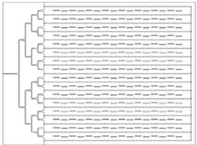
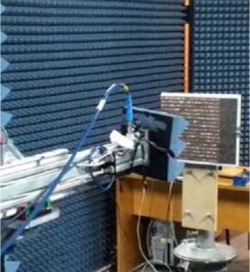
Fig. 2. Photograph of substrate integrated waveguide slot antenna array in anechoic chamber
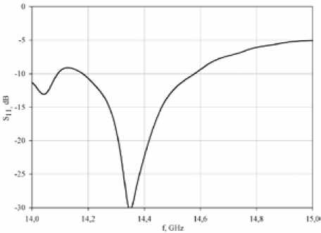
Figure 4 shows the measured amplitude and phase distribution across the antenna array. It can be seen that phase along the array does not change significantly, but amplitude slightly decreases towards the latest slots of array.
The simulated and measured radiation patterns in H -plane and E -plane at 14.4 GHz are shown in Fig. 5. It can be seen that the 3-dB beamwidth is approximately 7○ for the simulated and measured pattern in both planes.
The simulated and measured gains are shown in Fig. 6. Simulated maximum gain at the frequency of 14.4 GHz is 25 dBi, measured maximum gain is 22 dBi.

Fig. 4. Near field amplitude (left) and phase (right) distribution
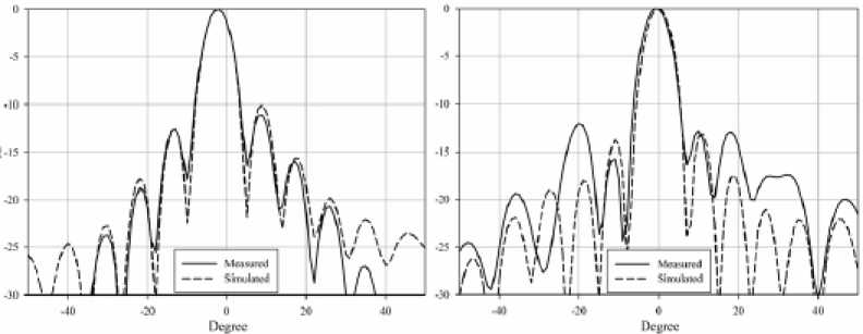
Fig. 5. Simulated and measured H -plane (left) and E -plane (right) radiation patterns
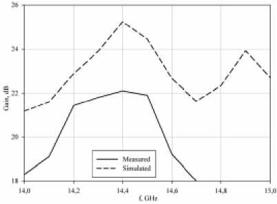
Fig. 6. Measured and simulated gain
Conclusion
This paper presents the results of development of the SIW slot antenna array. The antenna was fabricated and its characteristics are measured. The experimental results are in satisfactory agreement with the simulation results.
This work was supported in part by Ministry of education and science of Russian Federation (research in the scope of basic part of government job and contract № 02.G25.31.0041), Siberian Federal University.
References High gain Ku-band substrate integrated waveguide slot antenna array
- Устройства СВЧ и антенны. Проектирование фазированных антенных решеток: учеб. пособие для вузов/под ред. Д. И. Воскресенского. М.: Радио и связь, 1981. 432 с.
- Bozzi M., Georgiadis A., and Wu K.//IET Microwaves, Antennas and Propagation. 2011. Vol. 5. No. 8. P. 909-920.
- Chieh Jia-Chi Samuel, Pham Anh-Vu, Pidwerbetsky Alex, and Kannell George.//Microwave and optical technology letters, 2013. Vol. 55. № 8.
- Лемберг К.В., Назаров О.А., В.С. Панько, Саломатов Ю.П.//Изв. вузов. Физика. 2013. № 8/2. Т. 56. С. 105-107.
- Masataka Ohira, Amane Miura, and Masazumi Ueba. // IEEE Transactions on Antennas and Propagation, 2010. Vol. 58. No. 3. P. 993-998.
- Иванов А.А., Лемберг К.В., Панько В.С.//69-я научно-техническая конференция, посвященная Дню радио. 17-25 апреля 2014 г. Санкт-Петербург, 2014. С. 16-17.
- Дранишников А.С., Лемберг К.В.//Современные проблемы радиоэлектроники. Красноярск: СФУ, 2014.
