Hot water heating circuit with impulse cavitator

Author: Mitin Vladislav
Journal: Бюллетень науки и практики @bulletennauki
Section: Технические науки
Article in issue: 7 т.8, 2022.
Free access
An effective method of multifactorial influence on a liquid is cavitation, which leads to a change in the physicochemical characteristics of the liquid, its activation and heating. One of the devices, the principle of which is based on cavitation, is a cavitation heat generator. At present, the production of these units has been mastered by many manufacturers, and they appear in large numbers on the world market. Among the numerous designs of cavitation heat generators, a worthy place belongs to jet ones, which have the lowest pressure drop, but their efficiency is relatively low (from 20% to 40%) and does not meet modern requirements. The purpose of this work is to increase the efficiency of water heating in a cavitation heat generator based on the use of a pulsed mode of its operation. To achieve this goal, the following tasks were identified in the work: to develop a laboratory sample of a flow-pulse cavitator; to develop a diagram of a laboratory setup and a cavitator design; conduct hydraulic and thermal tests of the cavitator prototype, obtain the results and evaluate their effectiveness. Thus, the successful implementation of the goal of this work may encourage many industrial enterprises and households to abandon traditional heat supply systems and switch to modern sources of thermal energy, namely jet cavitation heat generators with a pulsed cavitator.
Cavitator, cavitation heat generator, jet cavitator
Short address: https://sciup.org/14124023
IDR: 14124023 | UDC: 621:314.6 | DOI: 10.33619/2414-2948/79/32
Контур горячей воды с импульсным кавитатором
Эффективным методом многофакторного воздействия на жидкость является кавитация, приводящая к изменению физико-химических характеристик жидкости, ее активации и нагреву. Одним из устройств, принцип действия которого основан на кавитации, является кавитационный теплогенератор. В настоящее время производство этих агрегатов освоено многими производителями, и они в большом количестве появляются на мировом рынке. Среди многочисленных конструкций кавитационных теплогенераторов достойное место принадлежит струйным, которые имеют наименьший перепад давления, но их КПД относительно невелик (от 20% до 40%) и не отвечает современным требованиям. Целью данной работы является повышение эффективности нагрева воды в кавитационном теплогенераторе на основе использования импульсного режима его работы. Для достижения поставленной цели в работе были определены следующие задачи: разработать лабораторный образец проточно-импульсного кавитатора; разработать схему лабораторной установки и конструкцию кавитатора; провести гидравлические и тепловые испытания прототипа кавитатора, получить результаты и оценить их эффективность. Таким образом, успешная реализация цели данной работы может побудить многие промышленные предприятия и домохозяйства отказаться от традиционных систем теплоснабжения и перейти на современные источники тепловой энергии, а именно струйные кавитационные теплогенераторы с импульсным кавитатором.
Text of the scientific article Hot water heating circuit with impulse cavitator
Бюллетень науки и практики / Bulletin of Science and Practice
UDC 621:314.6
At present, the priority direction of the energy strategy of the Russian Federation is to reduce the unit costs for the production of energy resources and increase the efficiency of their use through the widespread use of non-traditional energy sources. According to the current general scheme, the placement of energy facilities using alternative energy sources for the period up to 2035 will increase by 5% of all energy facilities.
Unconventional energy in Russia can be effectively used to supply consumers with energy, primarily in areas not covered by a centralized energy supply. These zones include the vast territories of Russia, where about 20 million people live. In addition, in today's society it is important that non-traditional energy has a factor to reduce the negative impact of large energy facilities on the environment. Air, soil and water pollution can be significantly reduced by switching from low-grade coal fuel combustion in small boiler houses to the use of non-traditional renewable energy sources.
In this regard, a study on the improvement of a jet cavitation heat generator based on the use of a pulsed mode is relevant and practically significant.
The studies were carried out in natural and laboratory conditions in 2022. Laboratory experiments were carried out in the laboratory of the Institute of Mechanics and Energy of the National Research Mordovian State University named after N. P. Ogaryov.
The author analyzed articles and patents of existing cavitators [1–4]. Studied articles on the topic of research work [5-7]. To identify the most efficient mode of operation, graphs of the amplitude-frequency and phase-frequency characteristics were plotted; for their construction, mathematical transformations of energy were performed along the constructed hydraulic circuit. A scheme of a laboratory setup with pulsed coolant circulation is constructed. The necessary equipment was selected and an experimental sample of a water heating circuit with a pulsed cavitator was assembled. Compiled heat balance for the selected circuit circuit with a cavitator. The technique and program of the experiment have been developed. Then the experiment was carried out and its data was processed.
The scheme of mathematical energy conversion is shown in Figure 1.
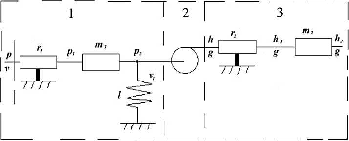
Figure 1. Hydraulic circuit
The circuit link equations:
1- link:
£ p = r 1 v2 + m 1 V + p2
I V = lp2 + V 1 '
2– link:
(P 2 = h^p
IV 1 = 9/p '
3– link:
(h = r2g + m2g + h2
-
9 = 9 ■
Table shows the calculated values of the amplitude-frequency and phase-frequency functions of the energy circuit for three operating modes with a cavitator frequency from 0,5 to 2,5 Hz.
Table
VALUES OF THE AMPLITUDE-FREQUENCY AND PHASE-FREQUENCY FUNCTIONS OF THE ENERGY CIRCUITS
|
Ω |
A1(jΩ) |
φ1(jΩ) |
A2(jΩ) |
φ 2(jΩ) |
A3(jΩ) |
φ3(jΩ) |
|
0,5 |
0,329198928 |
-0,11602 |
0,329280784 |
0,233059952 |
0,343244 |
0,038787 |
|
0,75 |
0,355749757 |
-0,32943 |
0,325550035 |
0,164050956 |
0,379334 |
0,023417 |
|
1 |
0,385757826 |
-0,42689 |
0,325037724 |
0,127061457 |
0,444639 |
0,014987 |
|
1,25 |
0,392141809 |
-0,32296 |
0,325943863 |
0,104645296 |
0,56554 |
0,009428 |
|
1,5 |
0,408936162 |
-0,19616 |
0,327872216 |
0,089958105 |
0,818111 |
0,005432 |
|
1,75 |
0,445743947 |
-0,11291 |
0,330879129 |
0,079855894 |
1,537494 |
0,002477 |
|
2 |
0,506211795 |
-0,06418 |
0,335308721 |
0,072704909 |
10,78891 |
0,000309 |
|
2,25 |
0,60522411 |
-0,03569 |
0,34182444 |
0,067568196 |
2,366241 |
-0,00125 |
|
2,5 |
0,785899092 |
-0,01869 |
0,351553944 |
0,063856707 |
1,126675 |
-0,00237 |
Based on the values obtained in Table, the graphs of the frequency response and phase response are plotted.
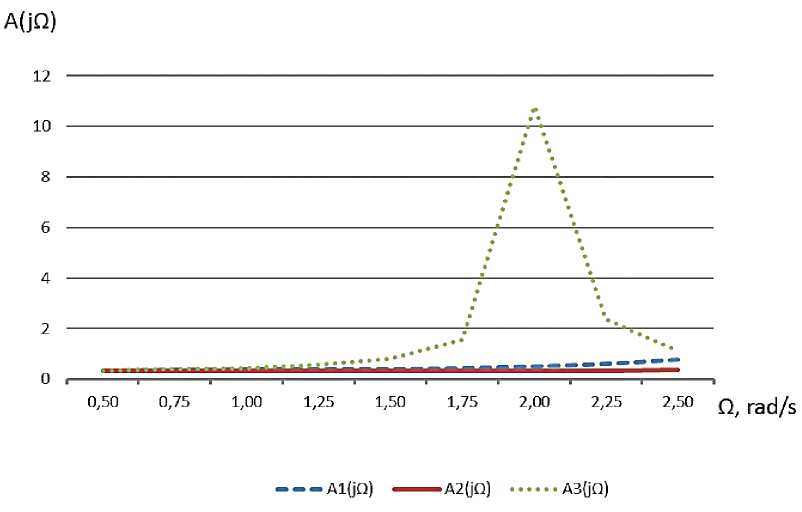
Figure 2. Amplitude frequency response
As can be seen from the graph of the amplitude-frequency characteristic (Figure 2), with a decrease in mass m to 25 kg and a decrease in compliance l to 0,0002 ms/N, the amplitude frequency decreases somewhat compared to the base values . With an increase in the mass m to 150 kg and an increase in compliance l up to 0,001 ms/N, a sharp increase in the amplitude by more than 10 times is observed. In this regard, this mode is the best. Figure 4 shows a diagram of a laboratory setup with a pulsed coolant circulation.
ϕ(jΩ)
0,3
0,2
0,1
-0,1
-0,2
-0,3
-0,4
-0,5
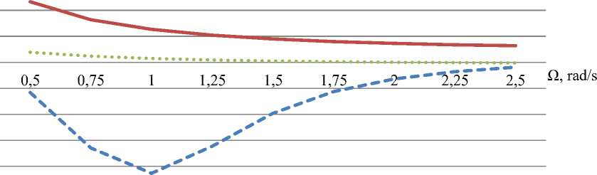
ϕ1(jΩ) ^^^^м ϕ2(jΩ) ϕ3(jΩ)
Figure 3. Phase frequency response
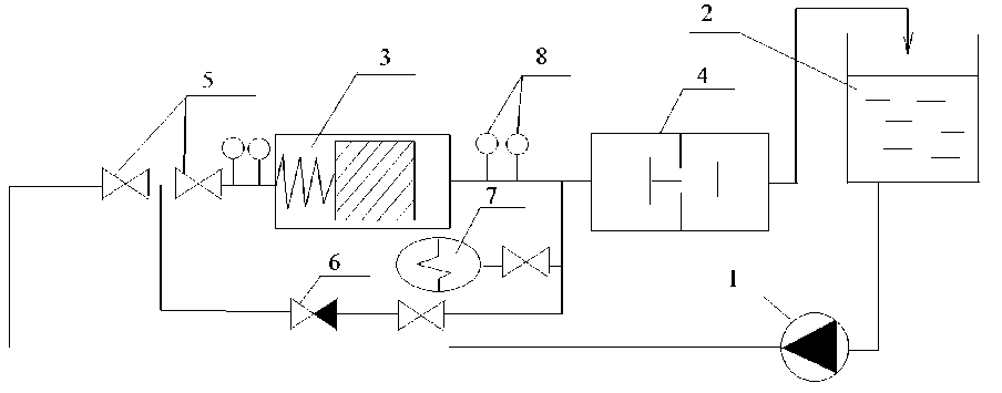
Figure 4. Scheme of a laboratory installation with pulsed coolant circulation
Based on the results of the experiments, graphs of temperature and pressure changes before and after the cavitator were plotted (Figures 4, 5).
The graph shown in Figure 4 allows you to track the dynamics of temperature changes before and after the cavitator over time. It can be seen from the graph that initially the temperature difference of the heated medium is — 0,4 °С. Within 1 minute, before the shock unit is switched on, this temperature value remains unchanged. After a time of 1 minute, the electric drive of the impact unit was switched on, which can be seen in the graph shown in Figures 5, 6. As can be seen from the graphs, at the moment the impact unit is put into operation, the temperature difference rises after and before the cavitator. This indicates the process of cavitation and heating of the coolant.
Approximately 30 minutes after launch, the temperature delta reaches its maximum and reaches a value of 1,67 °С.
Further, within of 20 to 25 minutes, the experimental installation operates in normal mode without deviations and as can be seen from the graph, heats the coolant constantly in the range of 1,1 °С to 1,5 °С. After 50 minutes of operation of the installation, the impact unit electric drive was switched off.
Temperature changes before and after the cavitator
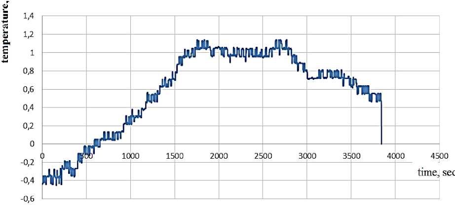
Figure 5. Graph of temperature changes before and after the cavitator
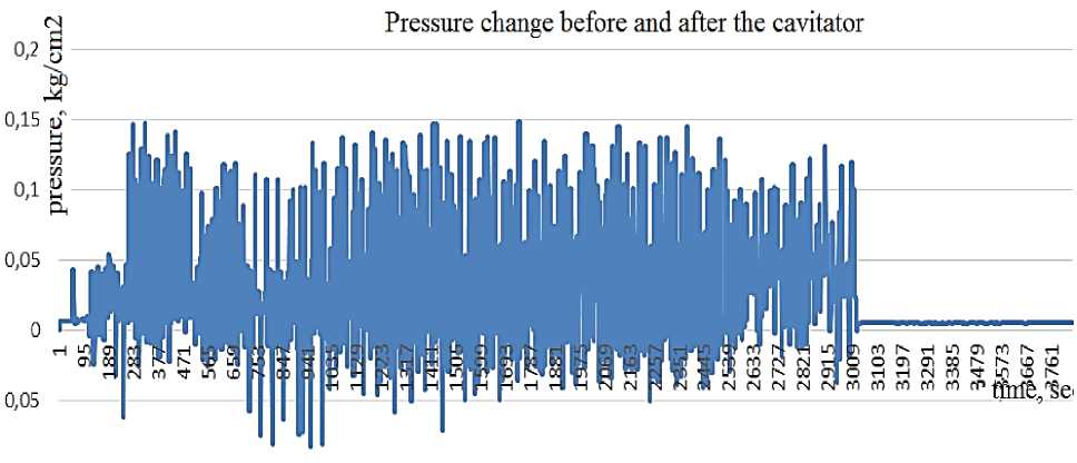
Figure 6. Graph of temperature changes before and after the cavitator
Conclusions
As a result of the analysis of literary sources, it was found that cavitation heat generators have been continuously improved in recent years. However, their efficiency is at the level of 30% to 40%, which does not meet modern requirements. Jet cavitators have the greatest potential, as they can successfully operate in a pulsed mode and thereby significantly increase efficiency. A laboratory sample of a flow-through pulsed cavitator has been developed that uses the inertia of a massive piston to increase the vacuum at the moment the shock valve closes. The laboratory setup allows testing a laboratory sample of such a cavitator with a frequency of 0,5 to 2,5 Hz. Hydraulic and thermal tests of a laboratory sample of a flow pulsed cavitator were carried out. The temperature difference after the onset of the steady state was 1,05 °C with a pressure drop of 0,12 bar.
A mathematical model of a circuit with a pulsed cavitator in the form of an energy circuit has been developed, which takes into account the active resistance of the liquid in the cavitator r 1 , the mass of water m 1 , the compliance l , heat losses r 2 , and the heat circulating mass m 2 . As a result of modeling, the optimal frequency was determined equal to 2,1 rad/s, at which the greatest efficiency is observed.
References Hot water heating circuit with impulse cavitator
- Левцев А. П., Макеев А. Н., Кудашев С. Ф. Кавитатор для выделения тепла в жидкости. Патент на изобретение №2619665. Зарегистрировано в Государственном реестре РФ 23 октября 2015 г.
- Ларионов Л. В., Томий И. И., Петухов В. Л., Миронидис Д. Е. Кавитатор для выделения тепла в жидкости. Патент на изобретение №2126117. Зарегистрировано в Государственном реестре РФ 23 апреля 1997 года.
- Таймаров М. А. Кавитатор. Патент на изобретение № 2516638. Зарегистрировано в Государственном реестре РФ 21 декабря 2012 года.
- Иванов Е. Г. Гидродинамический кавитатор. Патент на изобретение № 2603306. Зарегистрировано в Государственном реестре РФ 20 апреля 2015 года.
- Pandit A. B., Senthil Kumar P., Siva Kumar M. Improve reactions with hydrodynamic cavitation // Chemical engineering progress. 1999. V 95. №5. P. 43-50.
- Макеев А. Н., Левцев А. П. Импульсные системы теплоснабжения общественных зданий // Региональная архитектура и строительство. 2010. №2. P. 108-114.
- Левцев А. П., Кудашев С. Ф., Макеев А. Н., Лысяков А. И. Влияние импульсного режима течения теплоносителя на коэффициент теплопередачи в пластинчатом теплообменнике системы горячего водоснабжения // Современные проблемы науки и образования. 2014. №2. С. 89-89.
