Hydraulic calculations of earthen channels for reconstruction

Author: Khazratov Alisher N.
Journal: Журнал Сибирского федерального университета. Серия: Техника и технологии @technologies-sfu
Article in issue: 4 т.14, 2021.
Free access
The problems in the design, operation, and reconstruction of earthen channels analyzed on the example of Mirishkor canal. The need for a new approach to the reconstruction have been defined using the results of field study and HEC-RAS modelling software. Recommendations are given for improving the hydraulic calculation of irrigation canals.
Sediment transport, channel design, dynamic stable irrigation canal, distribution of deposition on cross-sections, hec-ras model
Short address: https://sciup.org/146281804
IDR: 146281804 | UDC: 626.34.004.68 | DOI: 10.17516/1999-494X-0327
Проблемы реконструкции земляных каналов
В данной статье анализируются проблемы проектирования, эксплуатации и реконструкции земляных каналов на примере канала Миришкор и необходимость нового подхода к реконструкции.
Text of the scientific article Hydraulic calculations of earthen channels for reconstruction
The main task of designing earthen channels is to calculate the dimensions of a durable channel shape in which irreversible channel deformation does not occur (Fig. 1). the deformation of a channel leads to a loss of overall stability and a decrease in channel capacity [1, 2].
All methods of designing earthen channels are conventionally divided into two groups. The first is the regime theory methods, which are devoted to determining the dynamic stability of a channel, in which equilibrium of the inflow and outflow of sediment assumed during a certain period. The second is a method devoted to the concept of tractive force and minimal energy dissipation, to determine the static stability of a channel. Because large hydraulic and transport structures are connected to large and medium-sized canals, it is considered dangerous to build them by checking the dynamic stability of their construction [2, 3].
In the Republic of Uzbekistan, the method of allowable velocities based on the theory of static stability is used for the design of canals. However, the cost of operating existing earthen irrigation networks remains high. One of the main reasons for this is the observed deformation of channels since the parameters adopted during the construction and reconstruction of canals do not take into account factors such as changing nature of water and sediment consumption, canal cross-section, flow gradient during exploitation period [2–5].
Methodology
In the studies, the flow velocity and depth were measured using a GR-21M hydrometric flowmeter (Fig. 2). HEC-RAS software was used to predict channel deformation and flow parameters. The HEC-RAS modeling system was developed by the Center for Hydrological Engineering of the U. S. Army Engineering Corps, which allows performing one-dimensional steady, one and two-dimensional unsteady hydraulic modeling; sediment transport and mobile bed computations, water quality modeling, etc. [5, 6].
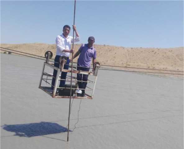
Fig. 1. Measurement process in Mirishkor channel PK245 station

Fig. 2. GR-21M hydrometric flowmeter
Field study
Currently, there are more than 196 thousand kilometers of irrigation canals for around 4,3 million hectares of irrigated lands in Uzbekistan. Cross-sectional geometry and the capacity of big irrigation canals, like Mirishkor, Karshi that deliver water from Amudarya River, has decreased due to sedimentation problems [3, 4].
In hydraulic calculations for the construction of canals and especially the reconstruction of canals (with parameters such as water consumption, turbidity concentration and fractional composition that change over a year), it is not enough to check a dynamic system such as an earthen channel for static stability with constant initial data. This is illustrated by the current poor technical condition of irrigation networks in operation, Fig. 3, 4.
From the diagram in Fig. 5, it can be seen that the designed normal water consumption at the head of the Mirishkor canal was Q = 136,3 m 3/ s , while the water consumption given during 2011–2013
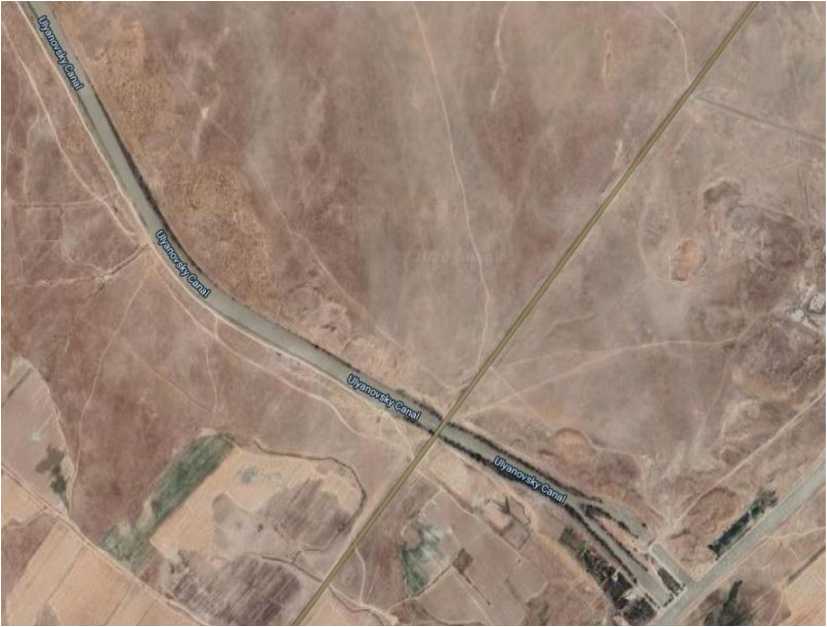
Fig. 3. Satellite image of the initial section of the Mirishkor canal
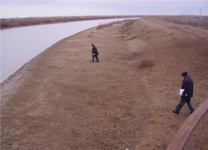
Fig. 4. General view of the Mirishkor canal in PK150 station
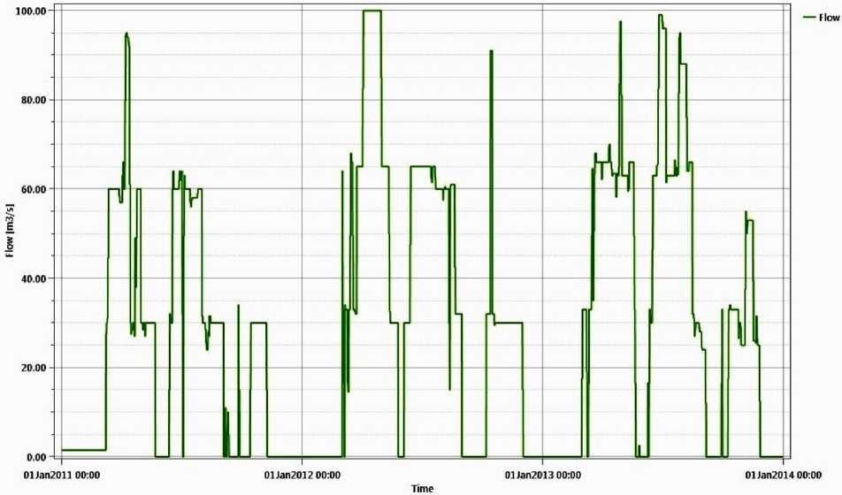
Fig. 5. Water consumption diagram of Mirishkor canal for 2011–2013
varied mainly in the range of 35–100 m 3/ s . As a result, we can say that during many years of operation, the canal has adapted to this water consumption, which has lost up to 30 % of its water capacity.
The results of flow rate and cross-sectional area measurements conducted at PK245 in 2016–2019 provided an idea of how the cross-section of the canal changes over time (Table 1).
Despite the fact that flow rate according to the measurement results of March 7, 2016 equals to Q = 54,4 m 3/ s , flow cross-section area is ω = 86,96 m 2, whereas flow rate on the 2nd April of 2018 – Q = 52,95 m 3/ s had bigger flow cross-section area ω = 92,74 m 2. This allows us to assume that the – 475 –
Table 1. Actual parameters of the channel section measured at different flow rates at PK245 station
|
№ |
Flow rate, Q, m3/s |
Width on the water surface, B , m |
Maximum depth of flowh, m |
Flow crosssection area ω , m2 |
Average flow velocity, ϑ, m/s |
Date of measurement |
|
1 |
54.403 |
42.4 |
3.05 |
86.965 |
0.626 |
07.03.2016 |
|
2 |
79.873 |
47.4 |
3.32 |
106.49 |
0.75 |
16.07.2016 |
|
3 |
84.683 |
48.7 |
3.52 |
104.39 |
0.811 |
14.04.2017 |
|
4 |
55.003 |
44.24 |
3.28 |
97.03 |
0.567 |
10.07.2017 |
|
5 |
51.95 |
41.42 |
3.31 |
92.74 |
0.56 |
02.04.2018 |
|
6 |
53,179 |
41,12 |
3,24 |
90.86 |
0,585 |
16.08.2019 |
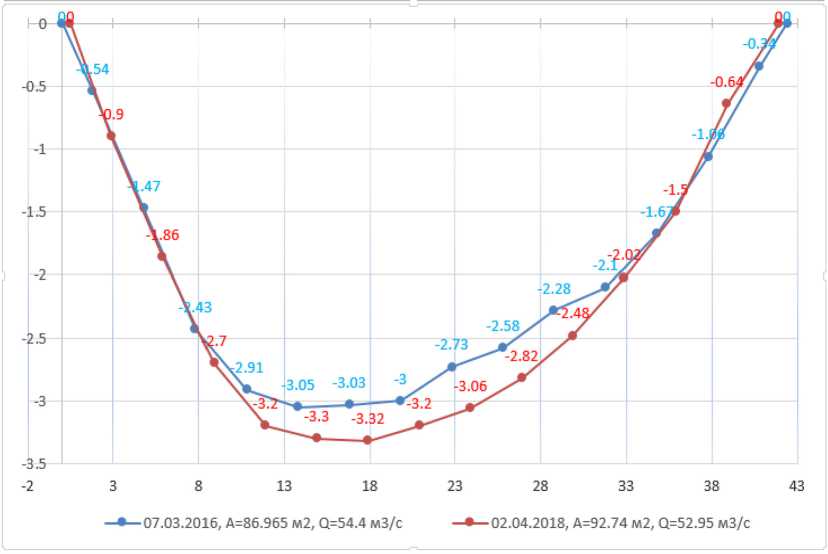
Fig. 6. Measurement results in 2016 and 2018 on Mirishkor channel PK245 station morphometric parameters of the channel change over time in response to changes in water and sediment parameters but generally achieve multi-year dynamic stability for flows in the range of 35–100, Fig. 6.
This means that in non-branched irrigation networks, such as the section of Mirishkor canal from PK0 to PK245, if the canal has sufficient capacity, there is no need for dredging during to overhaul the canal unless the maximum water consumption schedule in the subsequent canal operation does not change. Returning to the initial design parameters with a large cross-section area for a larger flow rate (136.3 m 3/ s ) than the current multi-year maximum consumption (35–100 m 3/ s ) of the canal, that will inevitably lead to a decrease in speed and a process of repeated intensive deposition.
Considering this, in the reconstruction of the channel, it is advisable to check the channel for dynamic stability, using modern modeling systems that allow predicting changes in the channel parameters during the exploitation period.
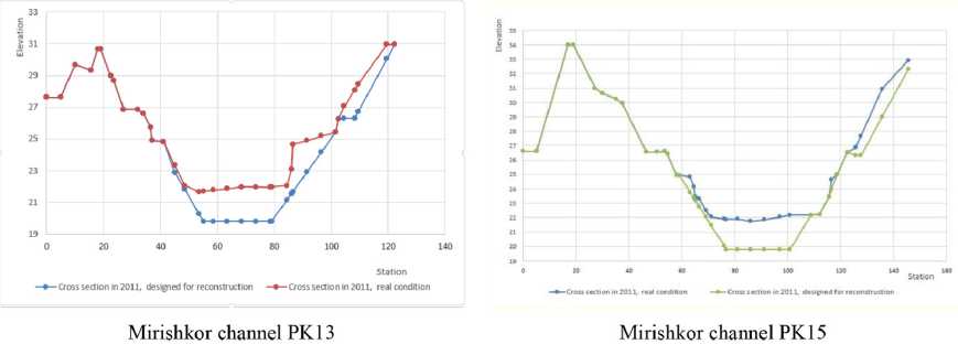
Fig. 7. Cross-sectional areas of Mirishkor canal in 2011 in their natural state and designed for reconstruction
It is also clear from Fig. 7 that in the design of the overhaul in the working project «Mirishkor canal cleaning from PK0 to PK215» developed in 2011 by the design institute «AGROMELIOMASLAHAT» mechanical cleaning for returning to initial design parameters is identified as the main task. There is no new approach to designing to reduce reconstruction costs.
Prediction of channel bed deformations using HEC-RAS modeling software
We selected a 950-meter-long canal section in the Mirishkor canal section PK9+50 to PK19 and then modeled the change in channel parameters during operation in 2011 using the HEC-RAS program based on the proposed geometric dimensions of the canal for reconstruction, Fig. 8.
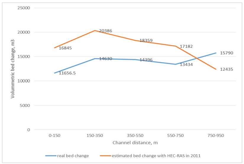
Fig. 8. Volummetric bed change of the Mirishkor channel in the section from PK9 + 50 to PK19
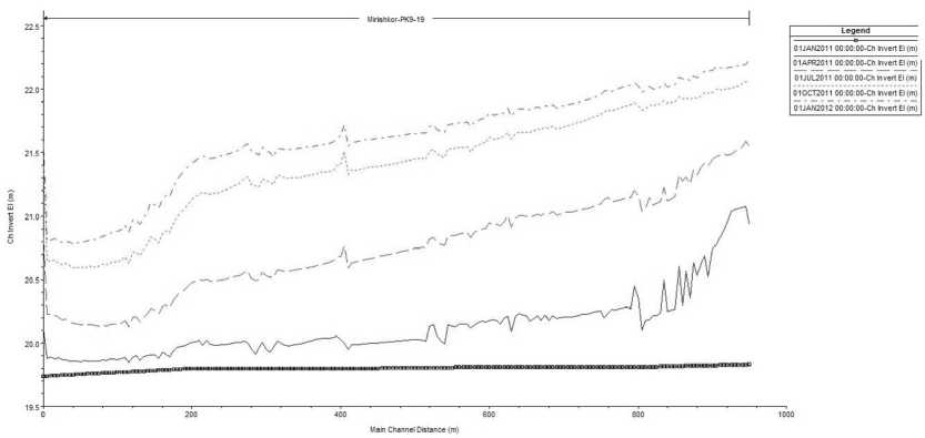
Fig. 9. Prediction of the evolutionary change of the channel invert elevation on the Mirishkor channel section from PK9 + 50 to PK19 in 2011 based on initial design values using the HEC-RAS program (flow direction from right to left)
From Fig. 8 it can be observed that the values of the volumetric bed change of the natural and modeled channel section have a general trend along with the longitudinal profile.
Figure 9 shows the results of forecasting the evolutionary change of the channel invert elevation using the HEC-RAS program based on the flow rate values observed during 2011 and the initial channel dimensions on the Mirishkor channel section from PK9+50 to PK19.
It can be seen that due to the relatively small water consumption in the canal (than initially designed flow parameters), it is possible to observe a tendency to increase the overall slope of the canal bottom in the year of intensive turbidity. That is, the channel bed evolves naturally during this time, depending on the equilibrium state of the channel transport, until the new deformation processes of the channel occur in the next high flow rate period, the slope increases.
Based on this important conclusion, it shows us that it is not necessary to set mechanical cleaning as the main goal in order to return the canal to its design values as the main task in the reconstruction of earthen channels such as Mirishkor canal. Instead, if there are no other hydraulic structures connected to the canal on the canal section or they are not adversely affected by the increase in water slope in the canal, it is necessary to reconstruct the canal by raising the canal embankment during the overhaul, Fig. 10. In this case, we will be able to increase the capacity of the canal by increasing the flow slope in the canal.
Change of channel cross-sections over time
Predicting the cross-sectional distribution of a deformed (deposited or eroded) surface during the exploitation period is accomplished by modeling programs, including the HEC-RAS program, by a uniform distribution of the deformed cross-section to the wetted perimeter, Fig. 11.
The prediction of the evolutionary change of the shape of earthen channels by empirical formulas has been studied by several scientists such as S. Kh. Abalyants, A. E. Mikhinov, S. S. Eshev [6, 7].
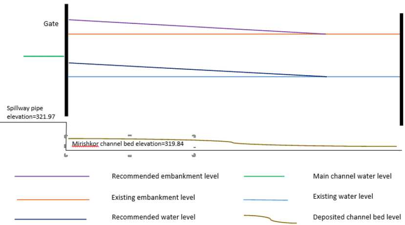
Fig. 10. Scheme for raising the canal embankment and increasing the water level gradient recommended for the reconstruction of section 1 of the Mirishkor canal
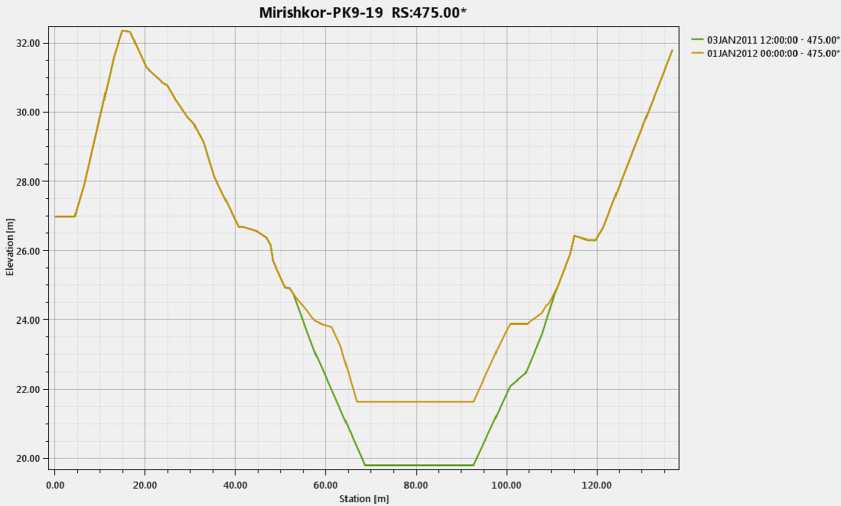
Fig. 11. Deformation of a cross-section during 2011 predicted in the HEC-RAS program in Mirishkor channel PK13 + 125 station
However, the laws of the cross-sectional distribution of deformation depend on the variable values of the shear stress across the cross-section and over time, making it difficult to predict.
Suppose that the average deformed area in a channel section can be predicted by formula (1):
Δ ω = W total / l , m 2,
where W total – the difference between the total deposited and eroded volumes in the channel section over time, m 3; l – channel section length, m .
Dividing deposited cross-section area Δ ω to initially designed area ω , we determine the specific deformed area D :
D = Δω / ω.(2)
To determine the specific deformation depth η , we divide the depth of a deposition in any vertical of the channel cross-section Δ h to the designed flow depth of this vertical h :
η = Δh / h.(3)
The depth of deformation in any vertical of a channel section can be expressed by formula (4) using the direct proportionality of specific deformation depth to the specific deformed area:
,, , Лю - Л,
Mi А ,(4)
со where А – distribution coefficient of deformation on cross-section. If this coefficient A = 1 at all verticals, then the deposited area of the cross section is evenly distributed in proportion to the flow depth.
We learned the natural conditions of cross-sections at non-curved sections of Mirishkor channel and determined the distribution coefficients of deformation on selected cross-sections, Fig. 12.
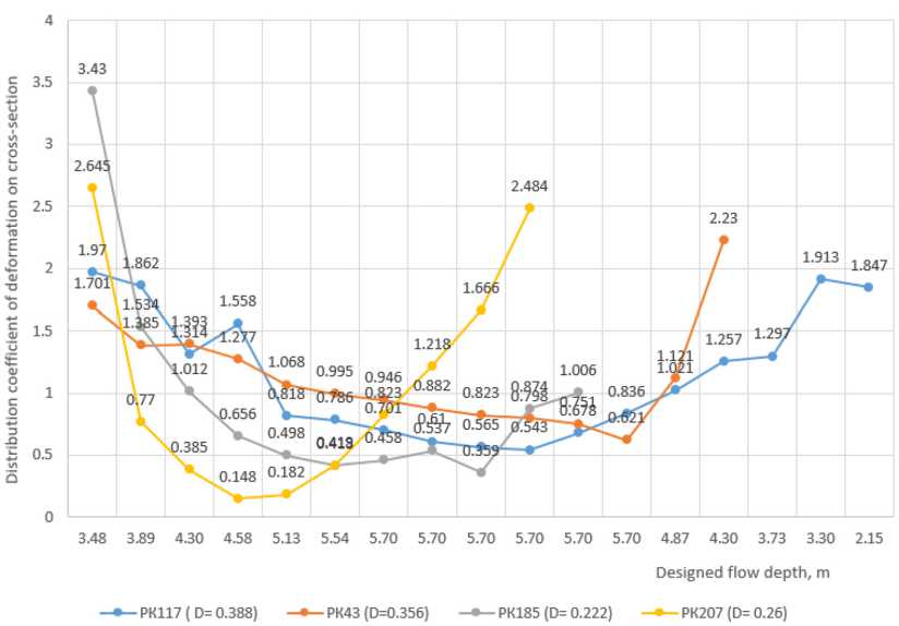
Fig. 12. Distribution coefficients of deformation on selected cross-sections at non-curved sections of Mirishkor channel
As can be seen from Fig. 12, in these sections, the cross-sectional distribution coefficient of deformation is less, at the bottom of the channel than on the sides of the channel. That is, when viewed concerning the flow depth, less deposition is observed at the bottom of the channel than to the side of the channel.
Conclusions and suggestions
-
1. Dredging the canal to return to its original design values should not be accepted as the main task in the reconstruction design to increase the capacity of Mirishkor canal. Reconstruction should take into account the dynamics of perennial changes in the parameters of water flow and sediments from the source, the prediction of morphological changes in the canal during the exploitation period, and the adoption of optimal channel parameters should be considered as the main task of reconstruction.
-
2. Given that the effect of a channel cross-section shape on a calculation of sediment transport capacity is very high, it is recommended to use the expressions we proposed above in the study of the distribution laws of deformation on cross-sections.
References Hydraulic calculations of earthen channels for reconstruction
- Арифжанов А. M., Фатхуллаев А., Самиев Л. Ўзандаги жараёнлар ва дарё чўкиндилари, T.: TIMI, 2017. 247 бет..
- Ибадзаде Ю. A. Транспортирование воды в открытых каналах, M.: Стройиздат, 1983. 272 с.
- Khazratov A. N. A sediment transport model for irrigation canals of Uzbekistan, European science review, Vienna, 2019, 3-4, 104-108. https://ppublishing.org/ru/journals/337/issue/51477/articles/4351
- Eshev S. S., Khazratov A.N, Rakhimov A.R, Latipov Sh.A. The study of bottom sediments in streams with mixed movement of clarified flow, Academicia, 2019, 9(9), 61-66. http://www.indianjournals.com/ijor.aspx?target=ijor: aca&volume=9&issue=9&article=006
- HEC-RAS, River Analysis System, User's Manual, US Army Corps of Engineers, Hydrologic Engineering Center, Davis, Version 5.0, 2016, 960 p. https://www.hec.usace.army.mil/software/hec-ras/documentation/HEC-RAS%205.0 %20Users%20Manual.pdf
- Абальянц С. Х. Устойчивые и переходные режимы в искусственных руслах, Л.: Гидрометеоиздат, 1981. 239 с.
- Михинов А. Е., Эшев С. С. Эксперименальное исследование формирования устойчивого поперечного профилия больших земляных каналов в нестационарных гидравлических условиях, Деп. в ВИНИТИ 1.10.1987, № 7080-В87. 39 с.
