Impact of Wireless Channel Model on 802.15.6 Standard Performance for Wireless Body Sensor Networks

Author: Maryam El azhari, Ahmed Toumanari, Rachid Latif, Nadya El moussaid
Journal: International Journal of Computer Network and Information Security(IJCNIS) @ijcnis
Article in issue: 5 vol.8, 2016.
Free access
Wireless Body Sensor Network (WBAN) is a set of wearable and implantable devices capable of measuring physiological parameters and monitoring patient with chronic disease where early diagnosis is highly demanded. Several models introduced the general characterization of WBAN devices path loss considering possible shadowing due to obstruction of the signal (by the human body or any other obstacles) as well as the different postures of the human body. This paper aims at reporting an overview of WBSNs technologies, particular applications, system architecture and channel modeling. Emphasis is given to the IEEE 802.15.6 standard which enables the development of WBAN for medical and non-medical applications. The standard's performance within a time based variation and log-distance path loss is presented based on various simulations.
Wireless Body Sensor Networks, Wireless Sensor Networks, path loss, medical applications, channel modeling, IEEE 802.15.6
Short address: https://sciup.org/15011522
IDR: 15011522
Text of the scientific article Impact of Wireless Channel Model on 802.15.6 Standard Performance for Wireless Body Sensor Networks
Published Online May 2016 in MECS
With Wireless Body Area Networks (WBAN) is a special type of Wireless Sensor Networks (WSNs) which provides remote monitoring of physiological parameters such as: body temperature, cardiac arrhythmias, Diabetes, high blood pressure etc...WBAN is being a highly demand telemedicine application for its advantage to continuously track patients with chronic disease where a sudden variation of a sensible parameter might lead to a serious damage if not death of the patient. Using such Wireless medical technology provides patient with more freedom, allowing him to perform casual activities without worrying about a wired device being plugged in [1].
WBAN are composed of several biosensors that can be categorized into in-body or/and on-body sensors capable of extracting, computing and transferring the measured data towards the destination through single-hop or multihop architecture where further analysis are taking place (see Fig 1-a and Fig 1-b).
Manuscript received January 16, 2009; revised June 11, 2009;
accepted July 21, 2009.
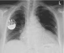
Fig.1-a. X-ray Image Showing an Implantable Pacemaker (in-body sensor)
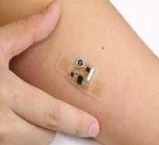
Fig.1-b. On-body Sensor
Biosensors are generally very diminutive which implies miniature battery size, therefore, WBAN are severely constrained in terms of energy [2] [3]. Many techniques have been proposed to minimize the energy consumption among biosensors involving finding optimal network architecture for data transmission, conceiving an adequate design for RF transceiver, and implementing efficient communication protocols. WBAN are now involved in many areas of wireless healthcare systems for both medical and non-medical purposes [4] as it could be used to track people over long distances via an implanted sensor as well as indicating the status of certain physiological parameters when an athlete is in process of performing some moves corresponding to numerous mobility patterns. Biosensors can also serve blind persons by implanting retina prosthesis which is biomedical implant technology currently being developed by many research institutions. And which purpose is to help out patients diagnosed with retinitis pigmentosa (RP) or macular degeneration [5].
In this paper we will first discuss the architecture system of WBAN. Next we will give more details on IEEE 802.15.6 standard and study the effect of WBANs on channel propagation. Finally we will finish up with conclusion and perspectives about our future work.
-
II. System Architecture of Wireless Body Sensor Networks
Careful system design of WBANs is highly required due to resource constraints of biosensors, to this end, many proposals for WBANs network architecture have been developed which can be divided into two essentials classes: single-hop and multi-hop architectures. A hop in our case refers to a particular network having the same characteristic (for instance a packet transmitted within the same WBSN is considered a one hop). A single-hop architecture consists of a number of biosensors (homogenous e.t heterogeneous) capable of measuring and sending the corresponding data to a unique end point unconstrained in terms of energy(running on AA batteries) such as the PDA where data measurements can be visualized and interaction with these biosensors is proceeded via an application interface. An example of such architecture is depicted in Fig2, which represents a cost based low power wireless ECG sensor developed by ASSIST Center group. The project aims to implement a wireless ECG using commercial off the shelf (COTS) components. The system can then process the ECG measurements and send it afterwards to a handheld device.
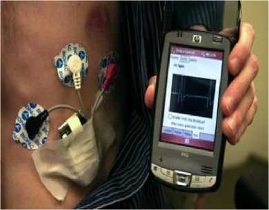
Fig.2. A Costs Based Low Power Wireless ECG Sensor in Operation, With a PDA Plotting ECG Real Time Signals.
However, in multi-hop architecture, the data is processed at the local end point PDA (filter and aggregate data packets) and then transmitted wirelessly towards medical servers via 3G, WLAN or GPRS where data is analyzed by professionals and instant decisions are taking place. Several projects are adopting a multi-hop architecture for data delivery, an example of such a project is CodeBlue [6], this project is a wireless infrastructure designed for emergency medical care, and including biosensors, PDAs and PC-class systems. CodeBlue main purpose is to ensure assessment of patient on scene, data transmission among caregivers and optimal allocation of hospital resources. The architecture is presented in Fig 3 highlighting query sending, path discovery and multipath response routing [7] [16].
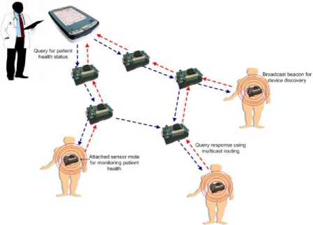
Fig.3. Illustration of the Code Blue Architecture and Operation
-
III. IEEE 802.15.6 Standard
Many standards in the market now are optimized to handle different types of non-medical applications such as: Zigbee [17] (designed specifically for industrial sensor applications), Bluetooth (for cable placement, data access points, adhoc networking) and Wi-Fi (video game consoles, PDAs and data networks). IEEE 802.15.6 task group [8] has been established to standardize WBAN communication paradigm and optimize biosensors constraints for both medical and non-medical applications. It specifies a short-range transmission inside or in the vicinity of an object using ISM as well as approved band frequencies for medical uses [13] (see Fig 4). The standard considers channel path variation in presence of persons shaped differently, quality of service supporting along with interference avoidance and specific absorption rate minimization.
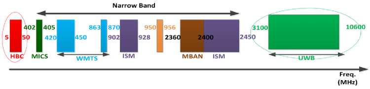
Fig.4. 802.15.6 Frequency Bands
IEEE 802.15.6 defines a Medium Access Control (MAC) layer supporting three Physical (PHY) layers: Narrowband PHY (NB), Ultra Wideband PHY (UWB), and Human Body Communications PHY (HBC). It operates with star and multi-hop topologies. In the one-hop topology, sensors and hub communicate directly without a mediator whilst in multi-hops topologies, extra sensors are deployed called relay nodes capable of handling and forwarding data towards end points [15]. The hubs are responsible for channel access organization by adopting one of the following three access modes:
-
• Beacon mode with beacon period superframe boundaries
-
• Non-beacon mode with superframe boundaries
-
• Non-beacon mode without superframe boundaries
IEEE 802.15.6 superframe is composed of multiple slots where the first slot is dedicated to beacon transmission for sensors synchronization and period length distribution which is proper to the first access mode, however in the second access mode, the hub uses the timed frames (T-Poll) instead of using transmitting beacons whilst in the last mode, each sensor separately determines its time base without employing T-Poll or beacon frames. An example of beacon mode with superframe boundaries is shown in Fig 5.
в
В2
ЕЛР1
RAP1
МЛР
ЕАР2 RAP2
МЛР
САР
Beacon period (superframe)
Fig.5. Illustration of the Beacon Mode with Superframe Boundaries
As illustrated in Fig 5, the superframe starts off with sending a beacon framework structure starts with a beacon packet followed by two consecutive periods: Exclusive Access Phase (EAP) and Random Access Phase (RAP), these periods can be repeated several times within the same beacon period as it can be set to null if not needed. The same rule is applied to Managed access Period (MAP) which can also be set to null value whereas CAP period is activated upon reception of B2 frame.
-
IV. Wbsn Channel Modeling: Body Area Network Propagation Channel
Current standardization main focus is on defining functionalities for the OSI protocol stack and more specifically for Physical (PHY) and Medium Access Control (MAC) layers, whilst regulating the allocation of electromagnetic spectrum correspondingly to the regions where used. A great number of body sensor networks use unlicensed bands for their application: UHF (Ultra-High-Frequency) ranging between 300 MHz and 3 GHz, the 2.4 GHz ISM band. The 5.8 GHz ISM band and UWB (Ultra-wideband).In addition to the aforementioned unlicensed bands, medical frequency spectrum can also be utilized for instance: MICS (Medical Implant Communication Service) and ULP-AMI (Ultra Low Power Active Medical Implant) where the frequency band is ranged between 401 and 406 MHz in communication with medical implants .It also allows bidirectional radio communication electronic implants such as a pacemaker. WMTS (Wireless Medical Telemetry Service) and MBAN (Medical Body Area Networks) allows on-body i.e. off-body sensors to work on spectrum bands for remote patient monitoring after being assigned to the relevant care centers. The human body is a lossy medium with a complex structure, composed of different tissues with dissimilar values of permittivity and conductivity which influences the radio propagation channels of communication links, this late experiences different behavior dependently on the type of body sensors. For instance; communication among on-body sensors are prone to multipath shadowing whilst in-vivo sensor propagated signals gets attenuated after being obstructing tissues with different characteristics. Research on the impact of the human body on radio channel has evolved in recent years.
In [9], authors investigated the path loss in electromagnetic signal propagation through the human body's channel in wireless capsule endoscopy, for this, a heterogeneous model was used to better highlight the effect of path loss, the results of the conducted simulations singled out the correlation between the path loss and the frequency, a high frequency leads to a high path loss and vice-versa. The recommended frequency for such capsule sensor was 450 MHZ where the actual frequency band is [450,900] Mhz. The corresponding path loss varied between -9dB and -38 dB, however, this still relevant to the body model characteristics such as: patient’s size, weight, age and gender.
In [10],authors analyzed an modeled the impact of path loss ,body shadowing and small scale fading caused by movements of human at 2.45 GHz. The experiments were performed in an anechoic chamber to isolate the human body effect on signal propagation and minimize multipath contributions where a resonant antenna with -10 dB bandwidth of approximately 55MHz is positioned at the test subjects central chest whilst the receiver is composed of an identical patch antenna mounted vertically on a non-conductive height adjustable stand at an elevation of 1.4m above the floor level. Different scenarios have been considered including mobile, stationary and rotation of human body. The results indicate that when the signal propagates from the sender (body worn antenna) towards the receiver (off-body antenna) without the obstruction of the human body, the signal attenuation is very low (within 0.5 dB) and can be modeled using the log-path loss equation. On the flip side, when the human body obstructs the signal path, other parameters have to be added to the log-distance path loss model such as: respiration and movement of the body. Also when the body rotates next to a wireless transceiver, the signal power deteriorates by as much as 50 dBm. In [11], authors studied the impact of indoor environment on narrowband radio channel path loss for body area networks operating around 2.4 GHz using a numerical human body phantom followed by real simulation scenarios within its environment-room walls, floor and ceilings.
The transmitter was placed on the human body chest whereas the receiver was located on the back of the torso and on the arm for another case. The simulation results has shown that the free-space modeling between the sender and the receiver can be used to approximate the signal attenuation over the bandwidth only when antennas are located close to one another; however, when the body obstructed the antennas transceivers in a free space environment, the signal propagation showed a very high attenuation up to 90 dBm while this value fell down to 30 dBm in indoor environment where the signal benefits of multipath propagation.
In [12], authors recorded a large number of simultaneous signal strength at 2.4 GHz using a developed small hardware carried by a person while the later performed some activities such as: working in the office, walking, running and sleeping. Continuous sampling of 200 Hz has been taken for up to 12 hours, and the results showed that the shadowing due to the person's body leads to the absorption of 60 dBm signal power emphasizing thus the non-efficiency of the logdistance path loss as a generic model, also the signal strength varied continuously at up to 50 Hz in respect to time-variation, which was exploited afterwards to develop a statistical model of some specific and generic links. The model is now being used as input parameters to wireless channel in Castalia simulator [14].
-
V. Simulation and Experiment
The simulation aims to highlight the impact of the channel model on the performance of the MAC protocol more specifically on 802.15.6 standard and this is done by considering the temporal and no-temporal variation of the channel model using the open-source Castalia simulator.
The average path loss map and temporal variation of the channel are defined in Castalia distribution (pathLossMap.txt i.e. TemporalModel.txt).The radio initial reception mode is set to “high” which stands for: 1024 for data rate (kbps), DIFFQPSK modulation type, bandwidth (MHz), sensitivity (dBm) and power consumed (mW) equal respectively to: 20,-87 and 3.1 (other predefined parameters can be found in Castalia distribution). The standard 802.15.6 beacon length period is set to 32 slots where the first slot is dedicated to sending beacon packet responsible of synchronizing sensors and handling new connections to the coordinator also notifying scheduled transmission of one or more sensor nodes. The beacon sending slot is followed by RAP (Random Access Period) period of 8 slots where sensor nodes contend to access the channel using CSMA/CA mechanism in respect to their priorities. In our simulation, we will be setting the rest of the beacon superframe periods to null allowing sensors to turn off their radio for batteries recovery capacity effect [7]. Data acknowledgement is activated and retransmitted in case no acknowledgement packet has being received after ACK_TIMOUT timer expiration, the retransmission attempt should be under a predefined threshold.
-
VI. Performance Analysis of 802.15.6 MAC Protocol In Temporal Environment
Our simulations consist in varying different input parameters and visualize afterwards the performance of 802.15.6 MAC protocol within a temporal environment (time-variation channel model) and non-temporal environment (log-distance path loss model) using Castalia 3.3 simulator. To this end, several metrics has been taken into consideration such as: data packet breakdown end to end delay and wireless channel fade. Five biosensors are positioned on the human body with predefined locations as mentioned in [14] (see Fig 6) where data packets are sent to the coordinator (usually a Personal Digital Assistant) and diverse metric performances are observed when initial parameters take different values.
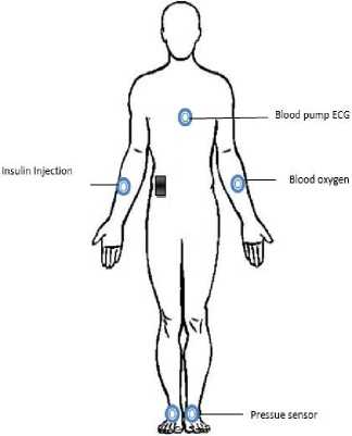
Fig.6. WBSN Network Topology
-
A. Varying transmission power
In this section, we vary the transmission power of biosensors and determine its impact on different metrics: Packet reception at both MAC and physical layers, latency at the application layer and channel Fade distribution, within a temporal environment. The power of transmission is set respectively to the following values: -10dBm,-12dBm,-15dBm and -20dBm. As can be shown in Fig 7 , there is a perfect correlation between the amount of power used for transmission and the average data packets received successfully by the coordinator at the first try, the maximum and minimum values of the pair (power ,data packet breakdown) are: (-10dBm, 1721,8) and (-20 dBm, 1584,8). when the transmission
power is increased, the coordinator tends to be within the communication range of the biosensor which increments the number of received data packets at the radio layer and this is observed in Fig 8 where the average number of failure due to non-sensitivity increases inversely to the transmission power leading similarly to loss of control packets (Acknowledgment packets) inversely to transmission power, thus once packets are successfully received they are automatically forwarded to the upper layer (MAC layer) where further operations are taking place (i.e. filtration). Fig 8 demonstrates that source of reception failure can be referred to interference and nonreception state of the radio due to loss of beacon packets necessary for synchronization, when the beacon is lost due to interference or below-sensitivity, the worse scenario can be defined as a sensor node RAP period colliding with beacon transmission and causing more interference and desynchronization but also data packet loss due to coordinator being in transmission state.
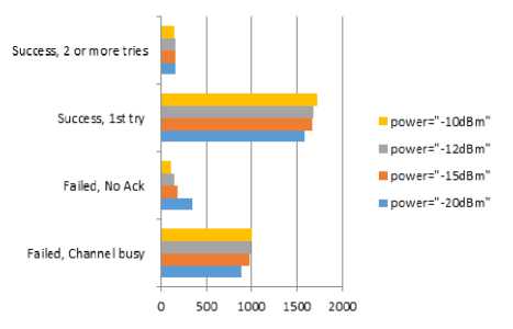
Fig.7. Packet Reception at the MAC Layer
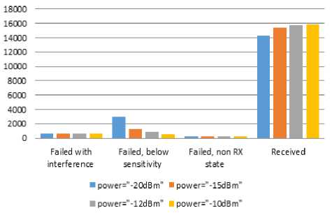
Fig.8. Packet Reception at the Physical Layer
Fig 9 shows the data packet latency at the application layer, as transmission power grows, the number of packets received at higher latency slows towards zero packets whilst it increases progressively in case of small transmission power (-20dBm). The latency at the application layer depends on the performance of MAC protocol, the non-availability of channel or loss of control packets (i.e. Acknowledgement mechanism is activated) for packet transmission often causes packets being stored for an exponential periods of time leading to saturation, which explains the important amount of packets received within the interval [600, inf), on the flip side, increasing the transmission power insures better packet reception and minimizes end-to-end delay, and this is clearly observed in Fig 9 where most of packets are received in [0,120ms] interval.
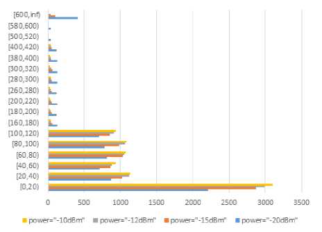
Fig.9. 802.15.6 Application Latency (A Varying Power)
-
B. Varying data rate transmission
In this section, we study the behavior of 802.15.6 MAC protocol within a temporal environment when data transmission rate is varied while the transmission power is set to -15 dBm for all biosensors including the coordinator. As can be seen in Fig 11, the number of received packets increments in respect to the rate. The increasing number of data packets to be sent leads to packet overflow with a maximum equals to 23218.2 due to non-availability of the channel for data transmission during the RAP period, also some control packets are lost in a way due to interference or below sensitivity especially when it comes to unconnected sensor nodes which maintains data packet in MAC buffer for a longer period of time until the connection with the coordinator is established and carrier sensing proved availability of the channel for transmission, moreover the polling i.e. posting mechanism was not considered in our case and this enhanced the increasing amount of buffer overflow but also the data packet latency at the coordinator where a considerable amount of data packet is received above 600 ms at higher data rate whilst 20 bps seemed to minimize the average end-to-end delay as most packets are received with a latency below 140 ms (see Fig 11).
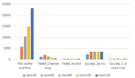
Fig.10. 802.15.6 Data Packet Breakdown
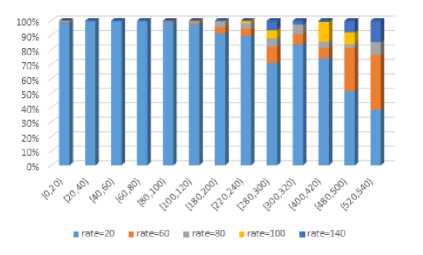
Fig.11. 802.15.6 Application Latency
Fig 12 shows channel fade distribution experienced by sensor nodes based on temporal variation model, as depicted in Fig 12, the channel fades values are mainly located within the three bucket intervals [-10,-5), [-5, 0) and [0, 5) where in each bucket, the number of packets experiencing fading increases inversely to the power of transmission reaching a maximum power equals to 37603 corresponding to -20dBm. This important amount of fade breaks connection between the sensor node and the coordinator which leads to control (i.e. data) packets lost in a way.
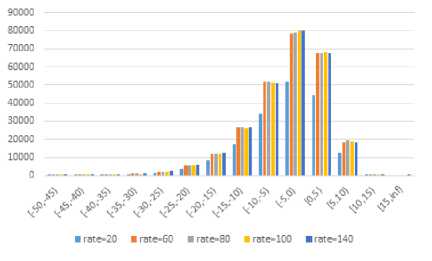
Fig.12. Channel Fading in Temporal Environment
Fig 13 shows the average energy consumption of biosensors in both cases where power and rate vary based on the set up parameters mentioned above, as can be observed, the average energy consumed when data rate varies is 0.01 mw much bigger than the value consumed within a simulation environment with varied transmission power, besides, the biosensors energy consumption converges considerably to the average value independently of the varied parameter and this is validated for the two cases. When the power of transmission varies and the rate is constant, the same amount of data is transmitted towards a coordinator that is connected to the biosensor. The link connection increases the reception probability of data and control packets and avoids retransmission of data packets when no acknowledgement has been received .After transmitting data or control packets, biosensor turns from transmission state to reception state where it consumed much more energy compared with transmission state as depicted in Castalia radio parameters (3.1 mw for RX mode versus a maximum value of 3.0 mw for TX mode) this explains the impact of power varying and rate varying parameters on energy consumption since the increasing rate tends to transmit more data packets (without considering those excluded due to buffer overflow),which means that the radio will spend more time on transmitting yielding to lower energy consumption units. In our simulation, the results are still the same for both temporal and non-temporal environment and the energy consumed is totally dependent on radio state rather than the size of data to be sent.
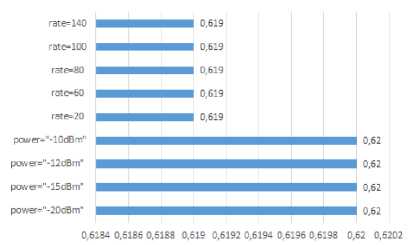
Fig.13. 802.15.6 Energy Consumption
-
VII. Performance analysis of 802.15.6 MAC protocol in non-temporal environment
In order to investigate the effect of the wireless channel with no temporal variation, we conducted a number of simulations in which again the power and data rate vary based on the same aforementioned simulation parameters. As can be noticed in Fig 14, the number of packets received under the two varying rate and power constraints is better when the channel has no temporal variation. These results are expected as temporal channel experiences fading which causes link disconnection between the sensor and the coordinator, the amount of channel fading distribution is totally absent in no temporal channel as links are maintained in a good state throughput the whole simulation period. Again, It is also noticeable that as data rate grows, the mac buffer start indicating signs of overflowing which is influencing the end-to-end delay at the application layer where a high amount of data packets is received in [600..inf) bucket indicating an important saturation with overflown buffers whilst in case of a varying transmission power, the end to end delay is minimized to the maximum as depicted in Fig 15: most of data packet are received under 140ms with absence of saturation effect since data rate packets is constant for all biosensors.
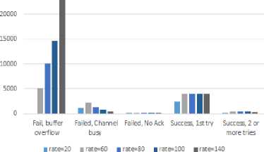
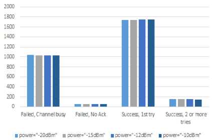
Fig.14. 802.15.6 Data Packets Breakdown in Non-Temporal Environment
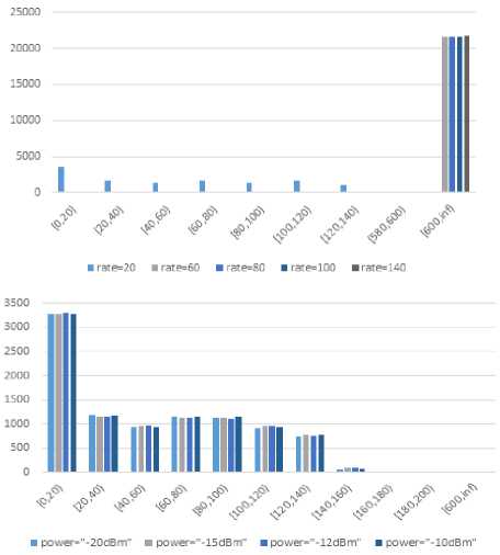
Fig.15. 802.15.6 Average end to end Delay in a Temporal Environment
-
VIII. Conclusion
WBANs present a revolutionized technology for medical system applications and its mainstream adoption is still in progress. Many researches nowadays in WBANs field tend to improve the performance of WBANs by resolving many constraints imposed by such type of networks where energy consumption constitutes a real problematic. In this paper, we presented an overview of WBAN architecture and its applications, we further studied the impact of wireless channel model on 802.15.6 standard performance using Castalia simulator and as a future work, and we will be focusing on enhancing the performance of 802.15.6 standard in terms of throughput, energy consumption and latency based on time variation channel.
References Impact of Wireless Channel Model on 802.15.6 Standard Performance for Wireless Body Sensor Networks
- Chen, S.L., Lee, H.Y., Chen, C.A., Lin, C.C., Luo, C.H.: A wireless body sensor network system for healthcare monitoring application. In: Biomedical Circuits and Systems Conference, 2007. BIOCAS 2007. IEEE, pp. 243{246 (2007). doi:http://dx.doi.org/10.1109/BIOCAS.2007.446335410.1109/BIOCAS.2007.4463354.
- Olivo, J., Carrara, S., Micheli, G.D.: Energy Harvesting and Remote Powering for Implantable Biosensors. IEEE Sensors Journal 11, 1573{1586 (2011). doi:http://dx.doi.org/10.1109/JSEN.2010.208504210.1109/JSEN.2010.2085042.
- Lee, S., Annavaram, M.: Wireless body area networks: Where does energy go? In: IISWC, pp. 25{35. IEEE Computer Society, (2012). http://dblp.uni-trier.de/db/conf/iiswc/iiswc2012.htmlLeeA12.
- Jamil. Y. Khan and Mehmet R. Yuce, "Wireless Body Area Network (WBAN) for Medical Applications", New Developments in Biomedical Engineering, Edited by Domenico Campolo, ISBN 978-953-7619-57-2, 724 pages, Publisher: InTech, Chapters published January 01, 2010 under CC BY-NC-SA 3.0 license.
- Liu, W., Humayun, M.S.: Articial retinal prosthesis to restore vision for the blind. In: Electronic-Enhanced Optics, Optical Sensing in Semiconductor Manufacturing, Electro- Optics in Space, Broadband Optical Networks, 2000. Digest of the LEOS Summer Topical Meetings, pp. 61{62 (2000).doi:http://dx.doi.org/10.1109/LEOSST.2000.86969910.1109/LEOSST.2000.869699.
- Malan, D., Thaddeus, F.J., Welsh, M., Moulton, S.: CodeBlue: An Ad Hoc Sensor Network Infrastructure for Emergency Medical Care. In: Proceeding on the MobiSys 2004 Workshop on Applications of Mobile Embedded Systems, pp. 12{14. ACM, (2004).
- Shnayder, V., Chen, B.-r., Lorincz, K., Jones, T.R.F.F., Welsh, M.: Sensor networks for medical care. In: Proceedings of the 3rd International Conference on Embedded Networked Sensor Systems. SenSys '05, pp.314 {314. ACM, New York, NY, USA (2005). doi:http://dx.doi.org/10.1145/1098918.109897910.1145/1098918.1098979. http://doi.acm.org/10.1145/1098918.1098979.
- Kwak, K.S., Ullah, S., Ullah, N.: An overview of ieee 802.15.6 standard. In: Applied Sciences in Biomedical and Communication Technologies (ISABEL), 2010 3rd International Symposium On, pp. 1{6 (2010). doi:http://dx.doi.org/10.1109/ISABEL.2010.570286710.1109/ISABEL.2010.5702867.
- Cotton, S.L., McKernan, A., Ali, A.J., Scanlon, W.G.: An experimental study on the impact of human body shadowing in on-body communications channels at 2.45 ghz. In: Antennas and Propagation (EUCAP), Proceedings of the 5th European Conference On, pp. 3133{3137 (2011).
- Hausman, S., Januszkiewicz, Impact of indoor environment on path loss in body area networks. Sensors 14(10), 19551 (2014). doi:http://dx.doi.org/10.3390/s14101955110.3390/s141019551.
- Chau, C.K., Wahab, M.H., Qin, F., Wang, Y., Yang, Y.: Battery recovery aware sensor networks. In: Modeling and Optimization in Mobile, Ad Hoc, and Wireless Networks, 2009. WiOPT 2009. 7th International Symposium On, pp. 1{9 (2009). doi:http://dx.doi.org/10.1109/WIOPT.2009.529162310.1109/WIOPT.2009.5291623.
- Boulis, A., Tselishchev, Y., Libman, L., Smith, D., Hanlen, L.: Impact of wireless channel temporal variation on mac design for body area networks. ACM Trans. Embed. Comput. Syst. 11(S2), 51{15118 (2012). doi:http://dx.doi.org/10.1145/2331147.233116110.1145/2331147.2331161.
- Alam, M.M., Hamida, E.B.: Surveying wearable human assistive technology for life and safety critical applications: Standards, challenges and opportunities. Sensors 14(5), 9153 (2014). doi:http://dx.doi.org/10.3390/s14050915310.3390/s140509153.
- Pediaditakis, D., Tselishchev, Y., Boulis, A.: Performance and scalability evaluation of the castalia wireless sensor network simulator. In: Proceedings of the 3rd International ICST Conference on Simulation Tools and Techniques. SIMUTools '10, pp. 53{1536. ICST (Institute for Computer Sciences, Social-Informatics and Telecommunications Engineering), ICST, Brussels, Belgium, Belgium (2010). doi: http://dx.doi.org/10.4108/ICST.SIMUTOOLS2010.872710.4108/ICST.SIMUTOOLS2010.8727. http://dx.doi.org/10.4108/ICST.SIMUTOOLS2010.8727.
- Maryam El azhari, Ahmed Toumanari, Rachid Latif, "Study of MAC Protocols for Mobile Wireless Body Sensor Networks", Network and Complex Systems, Vol 4, No 4 (2014).
- S. Saqaeeyan, M. Roshanzadeh, "IEATH: Improved Energy Aware and Two Hop Multipath Routing Protocol in Wireless Sensor Networks", IJCNIS, vol.4, no.5, pp.22-28, 2012.
- Ding, C., Wu, X., lv, Z.: Design and implementation of the zigbee-based body sensor network system. In: Proceedings of the 5th International Conference on Wireless Communications, Networking and Mobile Computing. WiCOM'09, pp. 3402 {3405. IEEE Press, Piscataway, NJ, USA (2009). http://dl.acm.org/citation.cfm?id=1737966.1738296.
