Impacts of voltage dips in doubly fed induction motor for wind turbine generation systems

Author: Ibrahim A.A., Solomin E.V.
Journal: Вестник Южно-Уральского государственного университета. Серия: Энергетика @vestnik-susu-power
Section: Альтернативные источники энергии
Article in issue: 4 т.18, 2018.
Free access
Renewable Energy Sources (like wind energy) minimize the demand for other types of power. Wind energy generation has become a major power in some countries, covering the essential share in the Energy Balance in Holland, Spain, Brazil, Germany, China and others. The construction of new Wind Power causes new challenges for the transmission distribution infrastructure. However, environmentally friendly Renewable Energy has recently become an important part of generation in industrial applications, worth for distributed lines expansion. A significant part of electric machines used in Wind Industry are doubly fed induction motors (DFIM) used as electric generators. They earned the leading market position over the recent decade and continue their run. The machines of this type offer operation stability along with affordable costs. The outstanding technical benefits include the ability for variable speed operation and independent control of reactive and active power. To protect the rotor side converter (RSC) from transient overcurrent during voltage dips, the crowbar circuit protection is usually used. The paper analyzes and investigates the dynamic behavior of the doubly-fed induction motor, back-to-back converter, and the rotor side converter during symmetrical voltage dips using the crowbar protection system with MATLAB/Simulink simulation. In addition, it studies the crowbar circuit affects the diodes, switches, and resistances at the low voltage ride through (LVRT) capability enhancement.
Doubly-fed induction motor (dfim), low voltage ride through (lvrt), crowbar, symmetrical voltage dips, wind turbine
Short address: https://sciup.org/147232706
IDR: 147232706 | UDC: 621.31 | DOI: 10.14529/power180405
Влияние провалов напряжения на асинхронную электрическую машину двойного питания в системе генерации ветроэнергетической установки
Возобновляемые источники энергии (такие, например, как энергия ветра) сводят к минимуму потребности в других видах энергоресурсов. Производство энергии ветра достигло значительного уровня во многих странах, например, в Китае, Голландии и Германии. Такой подход требует новых вызовов для распределенных электросетей. Возобновляемая энергия является одной из самых важных для человечества и обычно используется в промышленности благодаря покрытию пиков энергопотребления, не оказывая какого-либо воздействия на окружающую среду. Сегодня асинхронные машины двойного питания (DFIM) являются самыми распространенными на рынке производства электроэнергии за счет ветра. Данные изделия имеют экономически выгодные характеристики для работы в больших диапазонах переменной скорости вращения с независимым регулированием реактивной и активной мощности. Глухое замыкание на землю обычно используется для защиты преобразователя (RSC) со стороны ротора от переходных процессов во время падения напряжения. Целью представленной работы является анализ и исследование динамического состояния асинхронного двигателя двойного питания (DFIM), преобразователя встречно-параллельного включения и преобразователя со стороны ротора при симметричных провалах напряжения посредством системы защиты глухим заземлением с помощью программного комплекса MATLAB/Simulink. Кроме того, изучено влияние цепи глухого заземления (диода, переключателя и сопротивления) на повышение проходимости низкого напряжения (LVRT).
Text of the scientific article Impacts of voltage dips in doubly fed induction motor for wind turbine generation systems
According to the reports of World Wind Energy Association, the overall capacity of the wind turbines installed worldwide by the end of 2017 reached 539.291 Gigawatt (GW), added extra 2.6 GW in 2017. The installed power of wind turbines covers more than 5% of the global electricity demand. The share of grid tied large scale wind turbines is also growing compared to small turbines, reaching about 99% of the global wind market. Since the wind farms consist of big wind turbines, they require being more controllable both in reactive and active power, at the same time having a low voltage ride through (LVRT) capability when a fault occurs. The wind speed is constantly fluctuating, causing the correspondent changes in rotation frequency during operation. Because of this, the wind industry requires stable permanent control of both reactive and active power. However, it should be cost-effective. One of the solutions is partial-scale converter [1], controlling doubly fed induction motor (DFIM), widely distributed starting from 2002 as the main part of wind turbine generation system [2]. The stator of DFIM is connected directly to the grid, thus, the wind generator system is also exposed to grid instabilities [3]. The main intended purpose of the wind turbine is the grid power supply, maintaining the connection and actively participating in the entire system stability under and after possible grid voltage dip faults and disturbances. This capability of wind turbines is called Low Voltage Ride Through (LVRT) [4].
The most efficient approach to tuning DFIM to the LVRT is to use a suitable crowbar protection circuit on the rotor side of the DFIM [5]. The scientists and engineers researched the DFIM equivalent circuit and figured out that a suitable crowbar resistance is quite useful for LVRT. This method is based on the characteristics of rotor and stator fault currents taking into account the crowbar resistance [6].
When the voltage dips occur [7–10], huge currents are induced in the stator windings. Because of magnetizing coupling the large currents are also induced in the rotor windings. They may destroy the converters and increase the voltage of the DC-coupling. Thus the protection circuit is required to prevent the failure of the whole wind turbine. This protection of the back-to-back converter could be achieved by connecting the rotor circuit via a crowbar circuit protection, which in turn would protect the converters from huge transient rotor currents. When the rotor currents are short-circuiting the converters, the control of the DFIM is lost, so is the reactive and active power control on the stator side of the DFIM [11–12].
Fi g . 1 pres e n ts a fu l l dia g ram of th e DFIM w in d t u rbi n e . T h e AC / D C /AC c on v e rt e r c o n sist s o f tw o p a rt s : ro tor si de con v e rt e r (R SC ) a n d g ri d si de c o nv ert e r (GS C ) [13]. R S C an d GS C a re bot h v ol tag e sou rce c on v e rt e rs. Th e DC vol t a g e source, which is r e pre se n t e d by a c a pa c i t or, i s c on n e c t e d t o t h e DC pa rt o f t h e conv e rt e r. Th e GSC a n d t h e st a t or a re c o nnected to the three-p ha se g ri d v ia tr a nsform er c on v e rti n g l o w v ol t ag e in t o h i gh v olt a g e . Th e rot o r win din g is connected to the rotor si d e c on v e rt e r w i th s l i p a n d b ru s h e s. Th e m e ch a ni c a l po w e r g e n e ra t e d b y t h e w i n d t u rbi n e is t ran sforme d in to e l e c t ri c a l po we r b y t h e DFIM a n d t ra n s f e rre d t o t h e t h re e -phase grid via the stator and the converters.
T h e c on t rol sy st em of th e D FIM contains three sections [14]:
-
• R S C conv e rt e r, w hi ch c ont rol s re a c t iv e an d a ctive power in stator section.
-
• G SC c onv e rt e r t h at c on t rol s th e D C v ol t ag e t o k ee p i t f ix e d a n d c a n be u sed t o i n se rt e x t ra re a c t i v e power to the grid.
-
• Spee d c on t rol , w h i ch c on t r ols the electrical p o w er of th e c o n v e rt e r b y cha n g ing th e bl a de s pi t ch angle.
V ol ta g e di ps a re de f i n e d a s u n ex pe c t e d di st urb a n c e s of g ri d v ol t ag e , be c a use of f au l ts oc c u rri ng in t h e g ri d. Th i s pa pe r c on c en t r a t e s on s ymmet ri c v olt a g e di ps o n ly. A s soon a s vol t a g e di p i s re c ogn i z e d b y th e DFIM se nsors, i t i s re qu i re d t o c h e c k t h e pe rf or m an ce of th e st a t or f lux a n d a n a ly z e t h e problems r e su lt ing i n di sorde rs, a ppe a r i n g be c a use of th e di p. T h e c oi l s of th e rot or a n d st a t or c a n be e x pre sse d by two rotating coils DQ f or t h e r oto r an d two s t a t i o n a r y aP c oil s f or th e s t a t or a cc ordi n g t o space vector theo ry, pre se n ti ng th e f ol lo w in g equ a t ion s :
v 5 vs
v 5 vr
= RAS
^1
v P r
= Rsi a 5
= Rsi p s
d W 5
+ - - j to m W r ^
dt
+ dW. dt
+ d V p 5 dt
dWar ,
= Rriar + —“ + to mWpr dt d W₽ r
= Rrier +—7--to m Wa r dt
where the stator reference frame ( a - в ) is a station-
ary reference frame, the rotor reference frame ( DQ ) rotates at rotation speed to m . Subscripts “ 5 ”, “ r ” are used to signify space vector, when it is referred to the stator or rotor respectively; v5 and v r are the stator and rotor voltage vectors; ls and lr are the stator
—* —*
and rotor current vectors; T 5 and T r are the stator
and rotor flux vectors. The stator and rotor flux equations in the space vector form are expressed in the following equations:
—► w
s
s
—► w
s r
= L u is + L m i r
= L m i 5S + L r V
^ I w a s L s i a s + L m i a 5 I
[ W P 5 = L 5 i p 5 + L m i e 5 J
^
w a r L m i a r + L r i a r
W P r = L m i p 5 + L r i e r
, (4)
where Ls and Lr are the stator and rotor selfinductances, Lm is mutual inductance. In addition,
R5 and Rr are the stator and rotor resistances and to m is the rotor mechanical speed. Combining equations (1) and (4) and removing the stator current, the following equation is resulting:
diW 5 = v s dt s
- R^ w 5 + Rs—ir . ss r Ls Ls
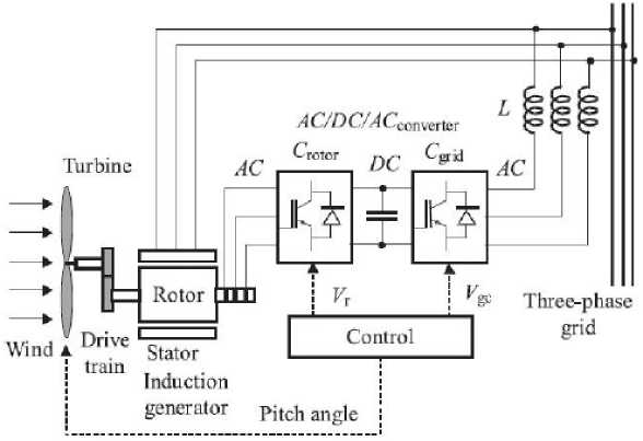
Fig. 1. A full diagram of DFIM based wind turbine
The shown transformations illustrate that when a voltage dip occurs, the stator flux cannot get to its steady state as fast as the stator voltage does. Each phase of the stator flux consists of the sum of a sin u soid and exponential functions with a time constant Ls Rs . The rotor current can make the flux decay rapidly, as shown in Fig. 2. In case of losing control, the rotor current is controlled by the mean of the RSC.
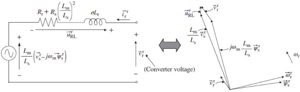
Equations (1) to (4) can be transformed into the following expression, as illustrated in Fig. 3a:
Vr = Lm ( VS - j ® m Ф r) +
Ls
+
(j. A2
R + | Lm I R rs
V L s )
V r d V r is + GLr , ir , dt
where g = 1 - Lm2 /Ls Lr .
The rotor current is the function of the stator flux, rotor and stator voltages, as well as of equivalent i n ductances and resistances. The space vector diagram at sub- synchronous speed is drawn in Fig . 3b above.
Loss of Control during Grid Voltage Dip
When the wind turbine runs at some steady point and an unexpected voltage dip occurs, this sudden change must be conveyed by immediate rotor voltage change to avoid an abrupt considerable increase in rotor current. Since the stator flux decays gradually, the rotor voltage will exceed the steady state. This may cause the disorder because of the stator voltage dip as shown in Fig. 4. Therefore, after several cycles, a new steady state should finally get back to the old steady state, which was before the voltage dip occurrence, but with lower stator voltage, which also gives a lower Tem and Qs. In order not to lose the control, keeping the rotor currents within safe limit value, it is required to set up the higher rotor voltage before the start of the voltage dip [15].
When severe stator voltage dip occurs, the entire system requires a crowbar protection from the exceeding currents and voltages, because of the loss of control during the dip. In DFIM-based wind turbines, the crowbar is connected at the rotor side, as illustrated in Fig. 5a. It protects the rotor converter. It is triggered when an irregular case is registered. The current is converted to the crowbar protection circuit and the rotor converter is isolated. Fig. 5b illustrates one phase equivalent circuit of the system when the crowbar is activated. As shown, once the crowbar protection is switched on, the circuit becomes an impedance divider. From Fig. 5a, the crowbar consists of rectifier diode, resistance, and controlled switch.
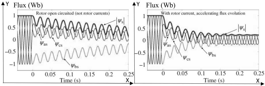
Fig. 2. Stator flux development in (PU) during an 80% voltage dip
а) b)
Fig. 3. Equivalent circuit of the DFIM for the analysis of voltage dips (a) and space vector diagram at sub-synchronism in a generator mode (b)
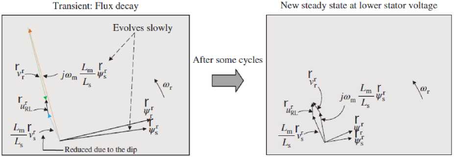
Fig. 4. Evolution of the space vector magnitudes from the first state when the stator voltage is reduced until the steady state is reached at the dip
а)
b)
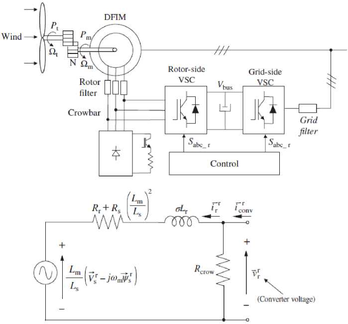
Fig. 5. System equipped with three-phase DC crowbar protection (a) and one phase equivalent circuit of the system when the crowbar is activated (b)
T o pr ov ide L V R T a bi l it y, th e win d tu r bin e m u st st ay co n n e ct e d t o t h e g ri d u nde r t h e v ol t ag e di p; th e n , t h e c ro wba r must be s w i t che d on a n d sw i t ch e d off remaining the connection of DFIM cir c u it w ith t h e g ri d. Th u s t h e f ol l o w ing se t of a c t i on s i s t a k en under significant voltage dip:
-
• T h e m a ch in e is g en e ra t in g p o we r a t a ce rt a in operating point.
-
• O n c e th e v ol t a g e di p h a ppe ns, t h e re is a t ime about (0.5–5) mi l l ise c on ds unt i l rot or control will reg i st e r th e di p. Du ri n g th is t ime t h e s y s t em is ou t of con tr ol an d t h e h ig h cu rre n t i s i n du c e d in rot or c on-
- verter, accompanied by increasing of DC bus voltage. The voltage dip is followed by:
-
a) High voltage in the DC link,
-
b) High current in rotor,
-
c) Grid voltage drop.
-
• When the dip is noticed, the crowbar protection is switched on rapidly, demagnetizing the DFIM. The entire rotor current runs via the crowbar.
-
• After the flux decays, the converter voltage can start controlling the DFIM. The protection circuit is disconnected and the rotor converter inactivated.
T h e c ro wba r prot e c t i on c i rc u it m ode l c o n sist s o f a rectifier diode bridge, resistance R cr o w ba r , and controlling switch, i mp l em en t e d u sing MA TL A B/ Simu-link as shown in Fig. 6.
Rcrowbar is about 0.2 Ω a n d t h e s wi tc h i s c on t rol l e d by th e c i rc u i t (C 1), w hi ch i s t ri gg e re d w h e n Ir > Ir limit or Vbus > Vbus limit . A ssu m i n g that the voltage dip occurred at the time of 3 s , th e s w it ch i s t ri g g ere d a n d th e c ro wba r prot e c t i on c i rcu i t a c t iv a t e d. When the time is equal to 3.1 s , the s w i tc h is n ot ac t i v e an d t h e c ro wba r prot e c t i on c i rc ui t de a c t iv a t e d. This process is shown in Fig. 7 b y u s ing s tep f un c ti o n imported from Simulink library.
T h e c on t rol c i rc u i t (C 2) oper a t ion , w h ic h tri gg e r the three-p ha se bri dg e , i s opposi te t o th e c on t rol c ir cu it ( C 1) d e sc ri be d a bov e , a nd u se d t o prot e c t th e r o t or an d th e g rid si de conv e rt e r (GSC ). W h en the crow b a r p rot e c t i on i s a c t i v a t e d, i t must disa bl e th e th r e e - p h a se bri dg e a n d i sol a t e the rot or si de c on v e rt e r ( R S C ) t o prot e c t i t f ro m hi ghe r c u rre n t an d v olt ag e as Fig. 8 and Fig. 9 show.
Configured three-phase pr o gr a mm ab le vo l ta ge source was obtained by generating t h e v o l tag e d i p at 90 % of the stator voltage including the h ar mo n ic s. T h is l ea ds to the system failure acco rd i n g to T ab le 1 , recovering the voltage after 3.5 s t o th e ful l r e c o v e r y a t 4.17 s .
D u ri ng th e v ol t a g e di p, t h e cu rre n t is f u lly provided by the d pa rt of st a t or c u rr e n t , losi ng th e t orqu e control of the wind turbine.
A simulation is carried out to research the dynamic behavior of a DFIM based wind turbine by using the crowbar protection circuit. The simulation is implemented in MATLAB/Simulink. In this simulation, the DFIM is exposed to a severe voltage dip of about 90% of the stator voltage for 0.50 s. Vector control approach is used to control GSC and RSC. It is assumed that the wind speed is constant (about 8.5 m/s) during the simulation period of time. Turbine rated voltage and power are taken as basic values.
To supply LVRT ability, a crowbar protection is used to avert the DFIM from being separated from the grid under hard voltage dip. The wind turbine system gets 90% dip of the stator voltage. Therefore, the voltage dip occurs at 3 s as seen in the fault analysis scope, while the remaining voltage of the grid is only 10% of normal voltage. When the crowbar protection is activated, the current runs through the crowbar protection circuit as shown in Fig. 10.
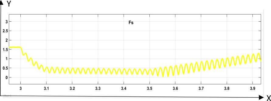
By changing the value of crowbar resistance Rcrowbar , the crowbar current could be higher or lower and the current changes faster or slower, also the flux decaying faster or slower, depending on the value of the resistance as shown in Fig. 11. During the crowbar activation, it can be seen that the entire rotor current runs through the crowbar protection circuit and the rotor side converter is protected as the higher current runs out of it, as shown in Fig. 12.
In addition, the stator current is high during voltage dip and cannot be controlled as shown in Fig. 13.
During this period, there is a high torque peak, which is followed by the higher crowbar current which cannot be controlled as shown in Fig. 14.
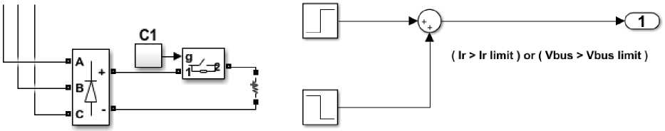
Fig. 6. Modelling crowbar protection circuit
Fig. 7. Modeling trigger control circuit, C1
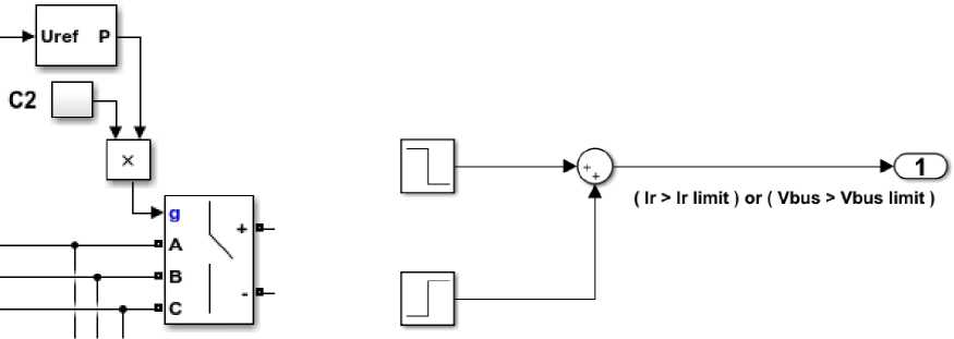
Fig. 8 Three-phase Bridge controlled by RSC and C2
Fig. 9 Modelling trigger control circuit, C2
Table 1
Fundamental harmonic generation
|
Order (n) |
Amplitude (pu) |
Phase (degrees) |
Sequence (0,1 or 2) |
|
|
A |
1 |
10 |
0 |
1 |
|
B |
0 |
0 |
0 |
0 |
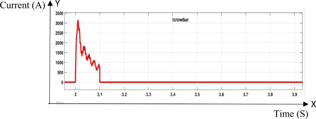
Fig. 10. Crowbar current when voltage dips occur from 3 s to 3.1 s
Flux (Wb)
Time (S)
Fig. 11. Flux decaying during voltage dips
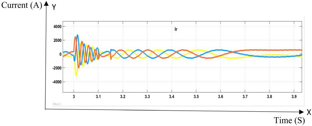
Fig. 12. Rotor current during voltage dips
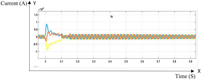
Fig. 13. Stator current during voltage dips
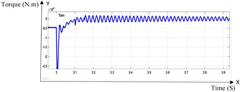
Fig. 14. Torque during voltage dips
The rotor side control scope shows that in the beginning of the voltage dip, the q component of the rotor current is equal to zero as well as after the crowbar activation as shown in Fig. 15. The mean value of the torque is zero and its values are oscillated due to the voltage dip as shown in Fig. 16. This is the evidence of losing the rotation speed control. Finally, considerable speed variations are shown in Fig. 17.
During the voltage dip, in accordance with the grid behavior, the d component of the rotor current becomes high to provide a reactive power to stator as shown in Fig. 18. The q component of rotor current, which provides the active power, is shown in Fig. 15 above.
Rotor current is also shown in Fig. 19. By con-
trolling the q component and d component of the rotor current (which is not equal to zero), the output is resulting in lower rotational speed fluctuations. The torque is controlled by the maximum power point tracking control method.
Comparing the stator voltage and the stator current, the reactive power can be shown as a phase shift. Fig. 20 shows stator voltage with crowbar protection:
Current (A) 4 Y
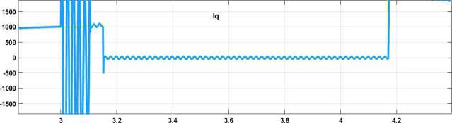
Fig. 15. The q component of the rotor current
Time (S)
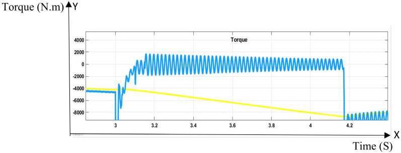
Fig. 16. Torque oscillation around zero mean value
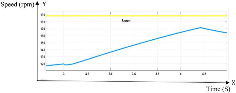
Fig. 17. Rotational speed variation
Current (A)fY
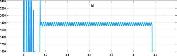
Fig. 18. The d component of the rotor current
-----► x Time (S)
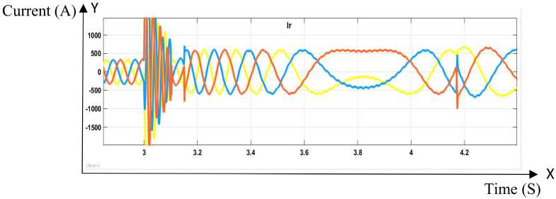
Fig. 19. The rotor current under voltage dips
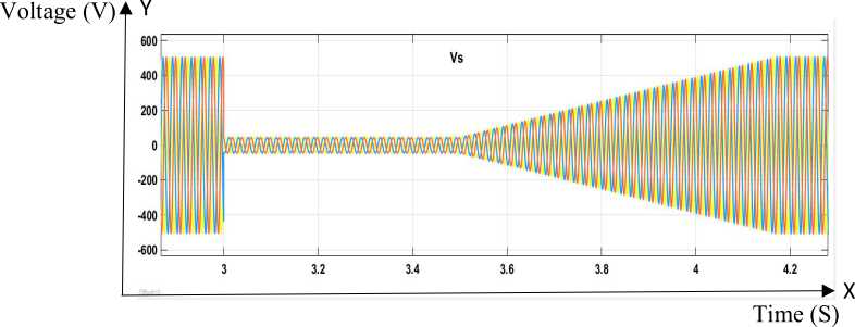
Fig. 20. Stator voltage with crowbar protection
DFIM-based wind turbines are exposed to significant grid voltage dips, which may destroy the entire converter system. Thus the wind turbine electric system must be separated from the grid with hard voltage dips. However, this approach would not meet the grid requirements for the wind turbine to use the low voltage ride through ability.
The crowbar protection circuit is activated when a severe voltage dip occurs. It disables the rotor side converter (RSC) to enable protection and all the higher current run through the crowbar resistance. The crowbar current fluctuations can be slower or faster depending on the value of the resistance. So the crowbar resistance should be carefully calculated or selected, as the higher current means the higher torque. When the crowbar circuit is deactivated, the control sets up again on the RSC side. During a voltage dip, the grid side converter (GSC) operates properly. Once the grid voltage is fully recovered, the control of rotor current is getting to the normal state, providing the proper torque using the maximum power point tracking method, controlling the rotational speed.
The crowbar system is required for the turbine to stay connected to the grid under hard voltage dips.
ВЛИЯНИЕ ПРОВАЛОВ НАПРЯЖЕНИЯ
НА АСИНХРОННУЮ ЭЛЕКТРИЧЕСКУЮ МАШИНУ ДВОЙНОГО ПИТАНИЯ В СИСТЕМЕ ГЕНЕРАЦИИ ВЕТРОЭНЕРГЕТИЧЕСКОЙ УСТАНОВКИ
А.А. Ибрагим1, 2, Е.В. Соломин1
References Impacts of voltage dips in doubly fed induction motor for wind turbine generation systems
- Mohsen R., Mostafa P. Grid-Fault Ride-Through Analysis and Control of Wind Turbines with Doubly Fed Induction Generators // Electric Power Systems Research, 2010, 80 (2), pp. 184-195. DOI: 10.1016/j.renene.2012.04.014
- Wind Power in Power Systems. John Wiley & Sons, , 2005. ISBN: 0-470-85508-8
- Mikel A., Modesto A., Aitor G. Neural Control for Voltage Dips Ride-Through of Oscillating Water Column-Based Wave Energy Converter Equipped with Doubly-Fed Induction Generator // Renewable Energy, 2012, 48, pp. 16-26, DOI: 10.1016/j.renene.2012.04.014
- Vinothkumar K., Selvan M.P. Novel Scheme for Enhancement of Fault Ride Through Capability of Doubly Fed Induction Generator Based Wind Farms // Energy Conversion and Management, 2011, 52 (7), pp. 2651-2658, DOI: 10.1016/j.enconman.2011.01.003
- Niiranen J.Voltage Dip Ride Through of Doubly Fed Generator Equipped with Active Crowbar // Nordic Wind Power Conference, 2004, pp. 1501-1507.
- Xu D., Wang W., Chen N. Dynamic Characteristic Analysis of Doubly-Fed Induction Generator Low Voltage Ride-Through Based on Crowbar Protection // Proceedings of the CSEE, 2010, 30 (22), pp. 29-36.
- DOI: 10.1016/j.egypro.2012.01.239
- Lluís Trilla, Oriol Gomis-Bellmunt, Adrià Junyent-Ferre, Montserrat Mata, Javier Sanchez Navarro, Antoni Sudria-Andreu. Modeling and Validation of DFIG 3MW Wind Turbine Using Field Test Data of Balanced and Unbalanced Voltage Sags // IEEE Transactions on Sustainable Energy, 2011, vol. 2, no. 4, pp. 509-519.
- DOI: 10.1109/TSTE.2011.2155685
- Wessels C., Fuchs F.W. LVRT of DFIG wind turbines - Crowbar vs. stator current feedback solution // EPE Wind Energy Chapter 2010, Symposium on, April 2010.
- Lopez J., Sanchis P., Roboam X., Marroyo L. Dynamic Behavior of the Doubly Fed Induction Generator during Three-Phase Voltage Dip // IEEE Transactions on Energy Conversion, 2007, vol. 22, no. 3, pp. 709-717.
- DOI: 10.1109/TEC.2006.878241
- Comech M.P., Sallán J., Lombart A. Modelling Wind Farms for Grid Disturbance Studies // Renewable Energy, 2008, vol. 33, no. 9, pp. 2109-2121.
- DOI: 10.1016/j.renene.2007.12.007
- Rahmann C., Haubrich H. J., Vargas L., Salles M.B.C. Investigation of DFIG with Fault Ride-Through Capability in Weak Power Systems // IPST '09 - Kyoto, Japan, 2009, paper 248, section 7A.
- Feltes C., Engelhardt S., Kretschmann J., Fortmann J., Erlich I. Dynamic Performance Evaluation of DFIG Based Wind Turbines Regarding New German Grid Code Requirements // IEEE PES '10 GM, 2010, pp. 1-7.
- DOI: 10.1109/PES.2010.5589562
- Gagnon R., Sybille G., Bernard S., Paré D., Casoria S., Larose C. Modeling and Real-Time Simulation of a Doubly-Fed Induction Generator Driven by a Wind Turbine // IPST '05 - Montréal, Canada, 2005, paper 162, section 26D.
- Erlich I., Wrede H., Feltes C. Dynamic Behavior of DFIG-Based Wind Turbines during Grid Faults // PCC '07 - Nagoya, 2007, pp. 1195-1200.
- DOI: 10.1109/PCCON.2007.373117
- Abu-Rub H., Malinowski M., Al-Haddad K. Power Electronics for Renewable Energy systems, Transportation and Industrial Applications // IEEE Press and John Wiley & Sons Ltd, 2014.
- DOI: 10.1002/9781118755525
