Implementation of Multi-Linear Gain Prior to Image Compression System in Remote Sensing Electro-Optical Payloads

Author: Ashok Kumar, Rajiv Kumaran
Journal: International Journal of Image, Graphics and Signal Processing(IJIGSP) @ijigsp
Article in issue: 3 vol.7, 2015.
Free access
Future high resolution instrument planned by ISRO for space remote sensing will lead to higher data rates because of increase in resolution and dynamic range. Hence, image compression implementation becomes mandatory. Presently designed compression technique does not take account of imaging system noise like photon noise etc. This ignorance affects compression system performance. As a solution, this paper proposes MLG (Multi Linear Gain) operation prior to main compression system. With digital MLG operation, captured image can be optimally adjusted to systems noise. Proposed MLG operation improves compression ratio. Simulation results show 15-30% improvement in lossless compression ratio. However this improvement depends on MLG gains and corner points which can be driven by system SNR plot. MLG operation also helps in improving SNR at lower radiance input, when lossy JPEG2000 compression is used as main compression. Up to 1-6 dB SNR improvement is observed in simulations. Proposed MLG implementation is of very low complexity and planned to be used in future missions.
Multi Linear Gain (MLG), image compression, JPEG, SNR, photon noise
Short address: https://sciup.org/15013538
IDR: 15013538
Text of the scientific article Implementation of Multi-Linear Gain Prior to Image Compression System in Remote Sensing Electro-Optical Payloads
Published Online February 2015 in MECS
In remote sensing electro-optical payloads, parameters like spatial resolution, radiometric resolution, spectral bands and swath determine the image data volume to be transmitted. Satellite power and transmission bandwidth limit real time data transmission capability. To meet the requirement of transmission bandwidth and image data volume, image compression becomes mandatory [1-2]. Various onboard image compression techniques have been used in space missions [3].
Image compression techniques can be lossless or lossy. These techniques were initially developed for digital still photography to reduce storage space. Lossy compression algorithms are generally developed according to contrast sensitivity function of human visual system [4], as main application of digital still photography is display, printing and feature extraction only. Lossy techniques emphasize preservation of contrast only and thus provide higher compression ratio. However imaging data from remote sensing is also used for scientific analysis and lossy compression techniques can have severe implications on scientific information.
In electro-optical imaging systems, system noise increases with input radiance. At higher radiance input, system noise is governed by photon noise and is of the order of 4-10 counts (~1 to 4%) [5-6]. Generally, this photon noise is not considered in design of image compression technique. By implementing digital MultiLinear Gain (MLG) prior to main compression system, captured image can be optimally adjusted to system noise, which can help in improving image compression performance.
This paper investigates the potential of digital MLG prior to image compression technique. JPEG2000 is considered as main compression system for simulation purpose. Results show the MLG helps in achieving higher compression ratio in case of lossless compression. MLG also helps in achieving higher SNR for lower input radiance. This makes MLG implementation more useful, as previous payload’s data analysis shows that around 6095% of data belongs to illumination of <25% albedo.
For a typical 8-bit system, SNR analysis is shown in section-II. Detailed effect of wavelet decomposition in compression system is also shown. MLG design is shown in section-III. Section-IV shows simulation results for lossless compression ratio improvement. Section-V shows SNR improvement for lossy compression.
-
II. Background
-
A. SNR response of a typical remote sensing electro-optical system
For any electro-optical imaging system, noise mechanism can be classified as [5, 7]
-
• A spatially determined so-called fixed pattern noise (FPN) and
-
• A stochastically random so-called temporal noise.
The FPN often is corrected by a flat field correction.
The remaining random noise is dominated by
-
• A static noise floor for low image signals, which increases with temperature and exposure time, and
-
• A dynamic noise part, which is driven by the photon noise and which increases according to the square root of the signal level.
This dynamic part of noise dominates the image quality of our raw data. Furthermore, the origin sensor noise should be a white noise as the incident photons act stochastically independent of each other.
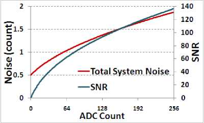
For any electro-optical imaging system, SNR can be approximated as
SNR
Radiance
Signal
Radiance
Noise
Radiance
Maxmum Detectable Radiance
J( NoisePhoton ^ +( NoiseDark M Noise Re adout Ь( NoiseElectronics ^
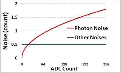
Fig. 1. Noise plot for a typical imaging system
Following are the few observations:
-
• Sensor SNR increases monotonically with input signal.
-
• SNR is governed by Photon noise at high
illumination.
-
• Maintaining the same accuracy throughout the dynamic range is of no use.
-
B. DWT decomposition in JPEG2000 compression
Today in digital photography, JPEG2000 compression system is used mainly. Characteristically of this technique is extensively researched [7-12]. JPEG2000 is based on DWT transform based. One step wavelet decomposition example is shown in Fig. 3.
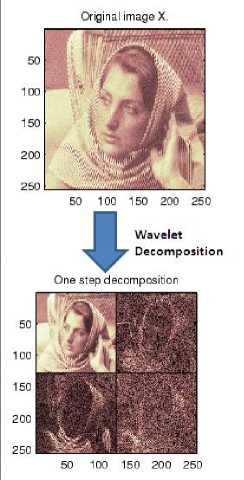
Fig. 3. Wavelet decomposition example
In all of its four components, different levels/types of compression are applied. Visually it is difficult to analyze the implication produced by DWT method. Let’s analyze DWT transform over 4X4 pixel dataset (Fig. 4).
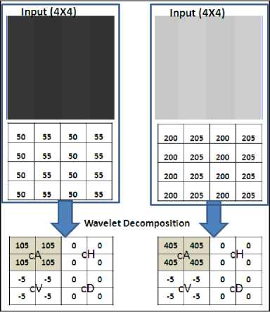
Fig. 4. Wavelet decomposition of 4X4 pixel datasets
It is quite evident that vertical frequency component ‘cV’ is same in both cases (independent of absolute count). However required radiometric accuracy at 50 count is much higher than the one required at 200 count. This ‘required accuracy’ information is not used in JPEG2000 compression system. Other transform based and prediction based compression system operates similarly.
-
III. Proposed mlg algorithm
MLG (Multi-Linear Gain) is one data compression technique, which has been used in Resourcesat-2 AWiFS payload (ISRO-2011) to accommodate higher radiometric resolution (12-bit) data in to existing 10-bit format of Resourcesat-1 interface [13-14]. The imageries received clearly demonstrate a better overall image quality as compared to Resourcesat-1 (10-bit radiometric resolution). For an imaging system shown in Fig. 2, MLG system is designed. Figure 5 shows designed MLG system response. For ADC count >58, MLG step size is kept as 2 ADC count. These corner points are derived based on system noise performance. Such MLG system can be approximated as lossless compression system. This MLG reduces 256 radiometric levels to 158 levels.
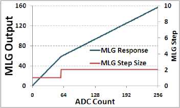
Fig. 5. Designed MLG response plot
It can be noted that MLG operation always adds quantization noise, hence minimal SNR degradation is expected at higher radiance. This is shown in Fig. 6.
ratio is noted. Same exercise is performed after MLG encoding.
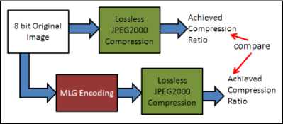
Fig. 7. Simulation methodology
Kakadu software [15] is used for JPEG2000 compression. Achieved compression ratios are compared.
B. Simulation Image-sets
1 1 m -1 n -1
Mean =—. —УТ Im age ( i , j ) m n i = o j = o
Std - dev =
m — 1 n — 1
—.— УУ [ Im age ( i , j ) - Mean ] 2 m nM
1 1 m -1 n -2
Line _ complexity =—.---- УУ llm age ( i , j ) - Im age ( i , j + 1)1
m n - 1 , =o j =o
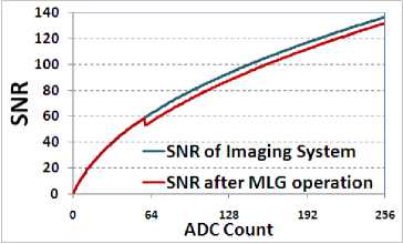
Fig. 6. Effect of MLG on SNR
If MLG is performed prior to JPEG compression, MLG will reduce high spatial frequency components based on system noise on absolute count. This can help in achieving higher compression ratio and better SNR.
-
IV. Improvement in compression ratio with
PROPOSED INCORPORATION OF MLG ALGORITHM
-
A. Simulation Methodology
Simulation methodology is shown in Fig. 7. Lossless JPEG2000 compression is applied directly on 8-bit raw image (original) image and achieved best compression
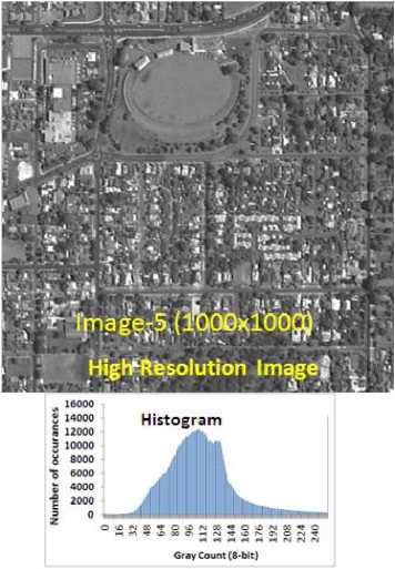
Fig. 8. Simulation image-5 and its histogram
-
C. Simulation Results
Fig. 11 shows that with MLG implementation higher compression ratio can be achieved. Reason behind this higher compression ratio is reduction of line complexity (shown in Fig. 12) due to MLG, as this leads to reduction in higher frequency components in image. Increase in compression ratio commensurate with data reduction by MLG operation. However the final improvement depends on contrast present in image.
Image-9 (1000x1000)
Very Low Resolution Image
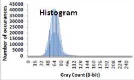
Fig. 9. Simulation image-9 and its histogram
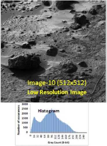
Fig. 10. Simulation image-10 and its histogram
Table 1. Image parameters of Simulation image-sets
|
Imagesize |
Mean |
Std-dev |
Line complexity |
|
|
Image-1 |
118.7 |
8.7 |
7.7 |
|
|
Image-2 |
128.4 |
8.6 |
5.8 |
|
|
Image-3 |
124.0 |
8.4 |
4.2 |
|
|
Image-4 |
56.9 |
7.5 |
5.3 |
|
|
Image-5 |
111.2 |
9.2 |
9.4 |
|
|
Image-6 |
127.8 |
9.3 |
9.2 |
|
|
Image-7 |
116.0 |
8.8 |
8.6 |
|
|
Image-8 |
97.4 |
7.4 |
2.5 |
|
|
Image-9 |
65.2 |
6.8 |
1.3 |
|
|
Image-10 |
512x512 |
90.6 |
46.4 |
7.1 |
|
Image-11 |
81.4 |
47.4 |
10.5 |
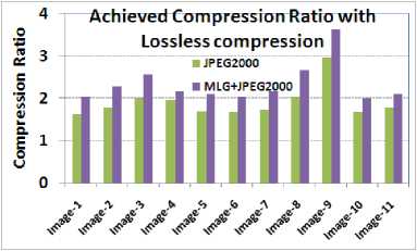
Fig. 11. Achieved compression ratio comparison
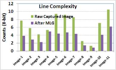
Fig. 12. Effect of MLG on Line complexity
-
V. Improvement In Snr With Proposed Incorporation Of Mlg Algorithm
-
A. Simulation Methodology
As count-wise SNR performance is important for remote sensing imaging application, full frame RMSE (Root Mean Square Error) computation is not helpful, thus not considered. Image-5 (1000X1000) & Image-9 (1000X1000) is considered for this simulation purpose. In this case, compression ratio is kept constant and at every original count SNR is computed [13,16]. Kakadu software v6.1 is used for this lossy JPEG2000 implementation [15]. Simulation methodology is shown in Fig. 13.
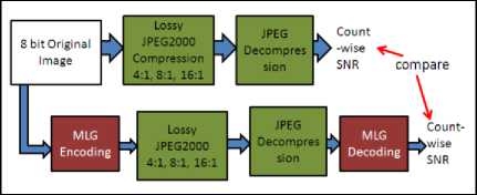
Fig. 13. Simulation methodology
For computing SNR at every count ‘S’, following equation is used. NoiseImaging-system is computed by Fig. 2. To increase accuracy of this measurement, only counts with at least 10 occurances are considered.
SNR ( S ) = 20log10
о
. ,. hist ( S )
J Z ( [ S — Re cov ered ( i , j ) ] 2 + [ Noise Im aging _ system ( S )f )
Y i, j if ( Orig in a l _ image i, j ) = ' S ')
-
B. Simulation Results
First of all, visual inspection is carried out in recovered images. Fig. 14 shows input image and Fig. 15 shows recovered image after 16:1 compression. Zoomed version is shown for better clarity. No artifacts are observed in recovered images. RMSE and Peak error comparison is also carried out, which shows no significant effect due to MLG operation.
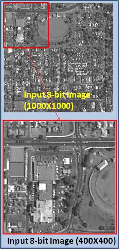
(3-000X1000)
Input8-bit Image (400X400)
Fig. 14. Input Image for simulation
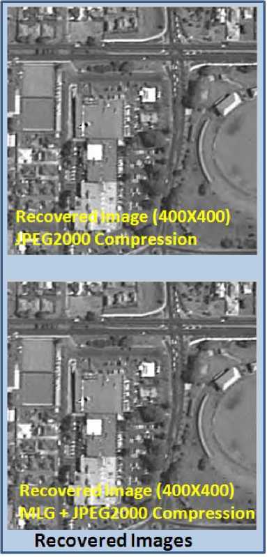
Fig. 15. Recovered image comparison with 16:1 image compression
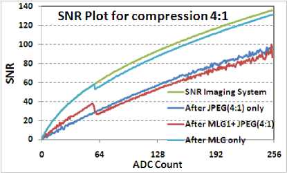
Fig. 16. SNR comparison for Image 5 with compression of 4:1
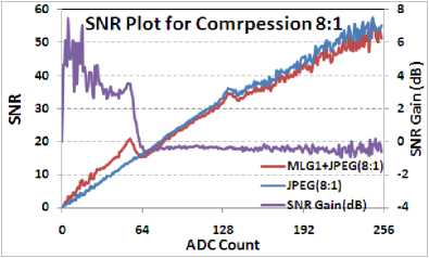
Fig. 17. SNR comparison for Image 5 with compression of 8:1
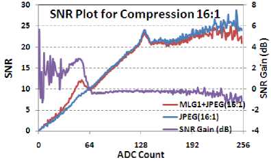
Fig. 18. SNR comparison for Image 5 with compression of 16:1
For image-9, SNR performance is shown in Fig. 19 with compression ratio 8:1. Around 2 dB SNR improvement is observed for lower illuminations.
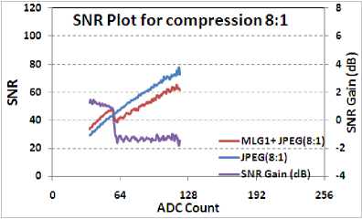
Fig 19. SNR comparison for Image 9 with compression of 8:1
-
VI. Conclusion
The proposed MLG implementation prior to main compression system helps in improving compression performance. Simulation results show 15-30% improvement in compression ratio in case of lossless compression and 1-6 dB SNR improvement for lower illuminations in case of lossy compression. Proposed MLG technique can be optimally adjusted to system noise performance. Proposed technique is of very low complexity and can be implemented easily on low end FPGA. Proposed technique is a suitable candidate for onboard implementation. Simulation results can be further verified on more number of images before final implementation.
Acknowledgment
We gratefully acknowledge the constant encouragement and guidance received from Shri DRM
Samudraiah- Prof. Satish Dhawan Scientist, Shri Saji A Kuriakose– DD-SEDA and Shri A. S. Kiran Kumar-Director SAC. We are thankful to our colleagues of Payload Checkout Electronics Group for providing the images.
References Implementation of Multi-Linear Gain Prior to Image Compression System in Remote Sensing Electro-Optical Payloads
- Ashok Kumar, Rajiv Kumaran, "Improvement in DPCM image comrpession technique", itSIP-2013, 18-19 Oct-2013, Mumbai-India, pp 280-284.
- Ashok Kumar, Rajiv Kumaran, "A low complex ADPCM image compression technique with higher compression ratio", IJCET, Vol 4 Issue 6, Nov-Dec (2013), pp 367-377.
- Guoxia Yu, Tanya Vladimirova, "Image Compression systems on board satellites", Acta Astronautica, vol 64, pp 988-1005, 2009.
- Majid Rabbani, "Digital Image Compression Techniques",Eastman Kodak Company, Volume TT 7, Spie Optical Engineering Press, 1995.
- Theuwissen A., "Solid-State Imaging with Charge-Coupled Devices", Kluwer Academic Publishers, 1995.
- Filippov, A., "How many bits are really needed in the image pixels?". http://www.linuxdevices.com/articles/AT9913651997.html.
- Gregor Fischer, "A Survey on Lossy Compression of DSC Raw Data", SPIE proceeding Electronic Imaging 2008.
- F. Ebrahimi, M. Chamik, S. Winkler, "JPEG vs. JPEG2000: An objective comparison of image encoding quality", Proc. SPIE Applications of Digital Image Processing, vol. 5558, 300-308, 2004.
- U. Steingrimsson, K. Simon, "Quality Assessment of the JPEG 2000 Compression Standard", Proc. of the CGIV 2004 Aachen, 337-342, Germany, April 2004 , 2004.
- U. Steingrimsson, K. Simon, "Perceptive Quality Estimation: JPEG 2000 versus JPEG", Journal of Imaging Science and Technology, (47), 572-603, 2003.
- M.J. Weinberger, G. Seroussi, G. Sapiro, "The LOCO-I lossless image compression algorithm: principles and standardization into JPEG-LS", IEEE Transactions on Image Processing 9 (8) (2000) 1309–1324.
- W.B. Pennebaker, J.L. Mitchell, "JPEG Still Image Data Compression Standard", Chapman & Hall, New York, 1993.
- Ashok Kumar, "Low complex ADPCM image compression technique", itSIP-2013, 18-19 Oct-2013, Mumbai-India, pp 276-279.
- Deviprasad: "Indian Remote Sensing Satellites- Resourcesat2 Mission Status", India Civil Commercial Imagery Evaluation Workshop, March 17, 2010.
- User Manual, Kakadu software v6.1.
- Rafel C Gonzalez, "Digital Image Processing using MATLAB".
