Implementation of Particle Swarm Optimization Algorithm in VHDL for Digital Circuits Optimization

Author: Garima Grover, Ila Chaudhary
Journal: International Journal of Information Engineering and Electronic Business(IJIEEB) @ijieeb
Article in issue: 5 vol.6, 2014.
Free access
In order to accomplish the targets of specified levels for reducing the hardware requirements of digital systems, innovative techniques are required to be implemented either at the device level, architectural level or gate level designs. In this paper one of the evolutionary techniques i.e. Particle Swarm Optimization Algorithm has been used to optimize digital circuits at the gate level on VHDL platform to draw an automatic, generalised and reliable technique to find optimum solutions with reduced gate count for the designing of digital systems.
Digital combinational circuits; VHDL, Particle Swarm Optimization; Search Space; Human methods
Short address: https://sciup.org/15013274
IDR: 15013274
Text of the scientific article Implementation of Particle Swarm Optimization Algorithm in VHDL for Digital Circuits Optimization
Published Online October 2014 in MECS
Reduction of area of digital systems and power consumption is a major concern in the field of digital design. Reduction in the component count and size in a digital system reduces its cost, physical size and weight, and hence increases system reliability. Moreover, reducing the hardware size leads to meet the minimum power consumption targets.
There are several methods of digital circuit minimization and can be classified as: Human Methods that covers Boolean Algebra, Karnaugh Map, Quine’ McClusky etc. and Computational Intelligence Methods e.g. Genetic Algorithm, Particle Swarm Optimization Algorithm etc. The computational intelligence methods have the advantage over human methods because they have the ability of being automated through programming. So the optimization is faster and hence less time consuming in case of Computational Intelligence Methods whereas human methods are comparatively tedious as minimizations are done manually.
This paper proposes the technique of Particle Swarm Optimization (PSO) developed for the optimization of 3 input generalized combinational circuit with VHDL as the platform. This platform has been chosen as being advantageous to be easily extendible for digital circuits with larger number of inputs and higher functionality making PSO a reliable technique for any type of digital design applications.
-
II. Particle swarm optimization algorithm
Particle Swarm Optimization simulates the behaviour of a swarm i.e. a group of birds. It is a computational method that optimizes a problem by running several iterations until the optimal solution is obtained. This stochastic optimization technique based on population was developed by Dr. Eberhart and Dr. Kennedy in 1995[1].
It is a technique implemented in various applications in order to determine an optimum solution. It simulates the intelligent behaviour of a group of birds moving from a place to their target. The birds adjust their velocity and speed to reach the target in accordance to their own position as well as neighbour’s position closest to the optimum solution. Similarly, initial solutions assumed are moved around in a search space logically following the PSO algorithm in accordance with the particular application and varying various parameters to reach the optimum solution.
PSO learned from the scenario and used it to solve the optimization problems [2].
-
> In PSO, each single solution is a bird in the search space termed as particles.
-
> Initially, depending on the application a search space is decided consisting of a number of solutions.
-
> Each particle’s initial position and velocity is assumed.
-
> These particles are moved around in the search space according to simple mathematical formulae over position and velocity.
V i+1 = W* V i + C 1 * rand 1 * (pbest – X i ) + C 2 * rand 2 *
(gbest – X i ) ......{1a}
Xi+1 = Vi+1 + Xi …...{b} and Xi+1 are updated velocity and position of each particle.
-
• V i and X i are previous iteration’s velocity and
position respectively of each particle.
-
• W is the inertial weight.
-
• C1 and C2 are acceleration constants.
-
• rand1 and rand2 are uniformly distributed random functions.
-
• pbest and gbest are personal best and global best positions of the particles.
The calculation of pbest and gbest depends on the fitness values of the particles which defines the closeness of the current solution to the optimum solution. Hence, pbest signifies the best position of particular particle till current iteration and gbest signifies the globally best particle closest to the target.
Values of all the parameters depend on the application for which PSO is being used [3].
-
III. Relating pso to digital circuits
-
A. Representation of Digital Circuit
To use the technique of PSO for the optimization of digital circuits, the circuits are required to be represented in the form of matrix [4][5][6].
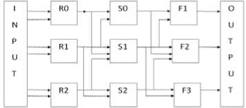
Fig 1. Structure of grid
For 3-input combinational logic circuit a 3×3 grid[4] has been used as shown in fig. 1 where inputs to each gate are obtained from the outputs of previous column. In the circuit, we have taken A, B and C as the primary inputs from the truth table of the human design method. R0, R1 and R2 are the outputs obtained from the gates in the first column. Similarly S0, S1 and S2 are the outputs obtained from the gates in the second column. F is the final output of the circuit obtained from PSO algorithm.
This grid is then represented in the form of a 7 × 3 matrix with seven rows and three columns. Each row represents a gate with first and third column elements as its input and second column element as the type of gate with the encoding scheme as shown in Table 1 and Table 2.
Table 1. Encoding of Column 1 and column 3
|
Matrix Value for column 1 and column 3 |
Represented Input |
|
1 |
A |
|
2 |
B |
|
3 |
C |
|
4 |
R0 |
|
5 |
R1 |
|
6 |
R2 |
|
7 |
S0 |
|
8 |
S1 |
|
9 |
S2 |
|
0 |
No input |
Table 2. Encoding of Column 2
|
Matrix Value for column 2 |
Represented Gate |
|
1 |
AND |
|
2 |
OR |
|
3 |
XOR |
|
4 |
NOT |
|
0 |
No gate |
-
B. Fitness Value Calculation
A fitness block has been implemented using VHDL as the platform [8]. This block has been used to decode the matrix to form a digital circuit and then computes automatically the outputs of the implemented circuit corresponding to all the binary combinations of primary inputs. It then compares the obtained output values with the actual outputs in accordance with the truth table outputs and hence cumulates the fitness value corresponding to each output matched.
For a 3-input combinational logic circuit there are eight possible combinational values and hence required fitness value will be eight [10].
-
C. Architecture of PSO for implementation in VHDL
As shown in fig. 2 fitness values of initially assumed position matrices of five particles are evaluated. Then, position matrix corresponding to maximum fitness value becomes gbest matrix. Also, position matrix with best fitness value of a particular particle till current iteration becomes pbest matrix corresponding to that particle. Position and velocity of all the particles are updated in update module in accordance with eq. 1a and 1b. Required Random functions are generated using Random Function Generator through Linear Congruential Algorithm [9]. Control logic block synchronizes the functioning of all the modules [11].
-
IV. Simulation results
In this paper, PSO has been implemented for the optimization[14] of a 3-input combinational logic circuit. Simulation results for full subtractor have been shown. The truth table of full subtractor i.e. the target is shown in Table 3.
Initial position matrices used for the simulation are:
X1 =
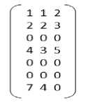
X2 =
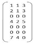
X3 =
|
13 2^ |
1 1 |
|
|
13 3 |
1 2 |
|
|
ООО |
X4 = |
О О |
|
4 15 |
4 3 |
|
|
ООО |
О О |
|
|
ООО |
5 1 |
|
|
7 4 0 |
4 3 |
О
X5 =
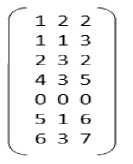
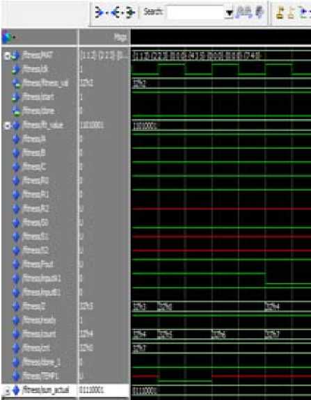
Fig 3a. Fitness value calculation of particular position matrix
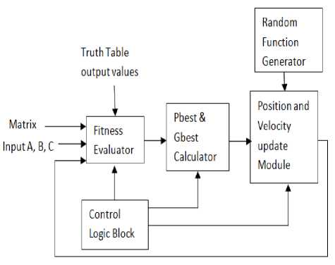
Fig 2. Architecture of PSO for implementation in VHDL
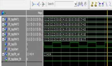
Fig 3b. Fitness block output for first iteration corresponding to all position matrixes initialized
Suitable parameter selection for PSO is extremely important for adequate convergence levels of the particles within the specified search space [10]. In this paper, initial velocity has been set as 0.1. Value of w has been set as 0.5 and c1 = c2 = 2. Random matrix is of the same order as the position and velocity matrix[12][13].
-
A. Fitness Evaluator
First iteration fitness value calculation results are shown in Fig. 3a and Fig. 3b. It shows the evaluation of fitness value of position matrix X1. Table 4 shows the fitness values evaluated for first iteration
Table 3. Required target of full subtractor
|
S/No. |
A |
B |
C |
BORROW |
DIFFERENCE |
|
1. |
0 |
0 |
0 |
0 |
0 |
|
2. |
0 |
0 |
1 |
1 |
1 |
|
3. |
0 |
1 |
0 |
1 |
0 |
|
4. |
0 |
1 |
1 |
1 |
0 |
|
5. |
1 |
0 |
0 |
0 |
1 |
|
6. |
1 |
0 |
1 |
0 |
0 |
|
7. |
1 |
1 |
0 |
0 |
0 |
|
8. |
1 |
1 |
1 |
1 |
1 |
Calculation of updated velocity and position is shown in simulation result of fig. 6.
Table 4. Fitness values corresponding to first iteration
|
Matrix |
X1 |
X2 |
X3 |
X4 |
X5 |
|
Fitness Value |
2 |
3 |
4 |
0 |
4 |
B. Pbest and Gbest Evaluator
Maximum fitness achieved is 4. Hence corresponding matrix is chosen as gbest matrix. Fig. 4 shows the simulation result for the calculation of pbest and gbest values.
gbest =
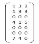
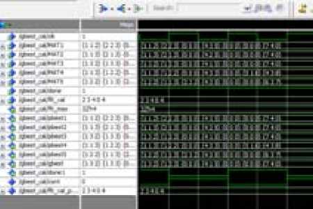
Fig 4. Simulation result for pbest and gbest calculator
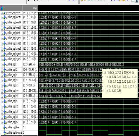
Fig 6. Velocity and Position update
E. Generating Circuit for Difference
Gbest matrix for computation of Difference corresponding to which fitness value is computed as 8 constitutes the circuit for difference. Resulting matrix is shown in Eq. 2. Simulation result is shown in Fig. 7 and resulting circuit is shown in Fig. 8.
C. Generation of Random Values
Calculation of uniformly distributed random matrix {0,1} using Linear Congruential Method is shown in Fig. 5 which generates new random values whenever position and velocity is to be updated.
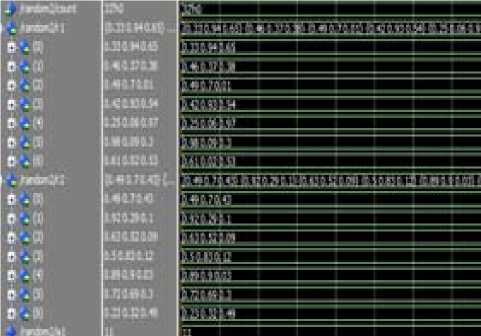
Fig 5. Random Number generator simulation
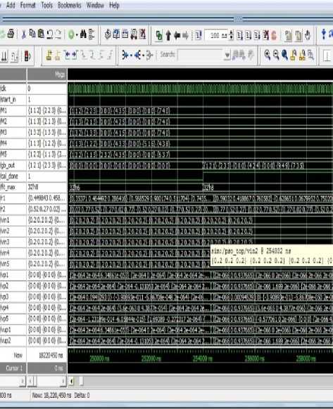
Fig 7. Matrix for generating Difference
D. Velocity and Position Update
Difference =
^1 2 1^
2 3 3
ООО
4 2 4
ООО
9 4 9
7 3 5^
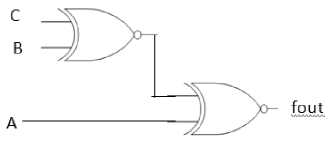
Fig 8. Circuit for Difference
Fig. 10 shows the circuit generated from Eq. 3
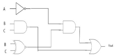
Fig 10. Circuit for borrow
G. Circuit for Full Subtractor:
Resulting circuit of full subtractor generated using PSO from Fig. 8 and Fig. 10 is shown in Fig. 11.
F. Generating Circuit for Borrow
The final gbest matrix for calculating borrow corresponding to which the fitness value is evaluated as 8 is the resulting matrix from repeated iterations. Fig. 9 shows the simulation result for generating the circuit of Difference and Borrow of full subtractor.
Borrow =
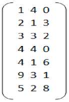
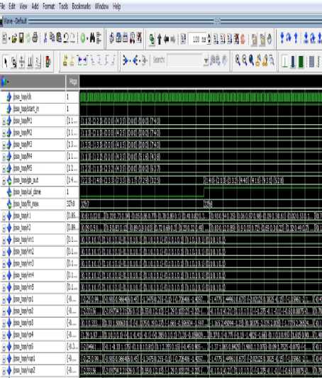
Fig 9. Matrix for generating borrow
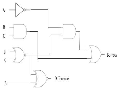
Fig 11. Circuit for Full Subtractor using PSO
Circuit of full subtractor generated using Karnaugh map technique is shown in Fig. 12.
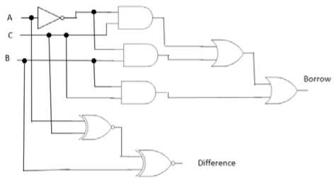
Fig 12. Full Subtractor using karnaugh map technique.
Comparison of gate count of both the circuits is given in Table 5. Full Subtractor circuit designed using karnaugh map technique requires 8 two-input gates. However, the circuit designed using PSO technique requires only 6 two input gates. Hence, in such a small circuit it is automatically reducing the overhead of two gates.
Table 5. Comparison of Karnaugh map Technique and PSO Technique
|
Circuit |
Gate count of circuit implemented through Karnaugh map |
Gate count of circuit implemented using PSO |
|
Difference |
2 |
2 |
|
Borrow |
6 |
5 |
|
Full Subtractor |
8 |
6 |
-
V. Conclusion and future scope
PSO technique has been proved to be a generalised technique to design smaller digital circuits with lesser gate counts in comparison to those designed using human design methods.
Moreover, larger is the circuit, more is the scope of its optimization using PSO technique. Also, VHDL platform has been used in the paper so as to make this technique easily extendible to design larger circuits with ease and lesser design time for being a digital design platform.
However, parameter selection in solving the problems using PSO plays a very significant role in obtaining optimum solution. It creates a lot of room for the research of the generalized parameter values to obtain optimum results.
This technique with a large number of modifications can be used to design circuits with large number of inputs and multiple outputs. Analysis of such techniques has been carried out such as hybrid particle swarm optimization or chaotic particle swarm optimization. For optimizing the combinational logics with multiple outputs other topologies except the grid can also be used.
References Implementation of Particle Swarm Optimization Algorithm in VHDL for Digital Circuits Optimization
- James Kennedy, Russel Eberhart, "Particle Swarm Optimization", Neural Networks, 1995, Proceedings IEEE conference vol. 4, page(s) 1942-1948.
- Gudise, V.G., Venayagamoorthy, G.K., "Evolving digital circuits using Particle Swarm", Neural Networks, 2003, Proceedings IEEE Joint Conference vol. 1, page(s) 468-472.
- Yuhui Shi, Russell C. Eberhart "Parameter selection in particle swarm optimization", Springer Link 1998, Evolutionary Programming VII, vol. 1447, page(s) 590-600
- Gudise, V.G., Venayagamoorthy, G.K., "Evolving digital circuits using Particle Swarm", Neural Networks, 2003, Proceedings IEEE Joint Conference vol. 1, page(s) 468-472.
- Carlos A. Coello Coello, Erika Hernandez Luna & Arturo Hernandez, "Use of Particle Swarm Optimization to design combinational logic circuits", Springer Link 2003, Embedded Systems, Vol. 2606, page(s) 398-409.
- Jen-Pin Yang; Electr. Eng. Dept., I-Shou Univ., Dashu, Taiwan; Chih-Kung Kung; Fang-Tsung Liu; Yu-Ju Chen, "Logic Circuit Design by Neural NeTwork and PSO Algorithm", PCSPA 2010, Proceedings IEEE Conference, page(s) 456-459.
- Ushie, James Ogri, Obu Joseph Abebe Etim, Iniobong prosper Department of Physics, Department of Physics, Department of Physics, University of Calabar, University of Calabar, University of Calabar, Calabar, "Optimising digital combinational circuit using particle swarm optimisation technique", Lat. Am. J. Phys. Educ. Vol. 6, No. 1, March 2012, page(s) 72-77.
- Feng Tian; ch. of Inf. Eng., Hebei Univ. of Technol., Tianjin, China ; Zhenbin Gao;YiCai Sun "VHDL Modeling of Particle Swarm Optimization Algorithm", CISE 2009, Proceedings IEEE conference, page(s) 1-4.
- Par Kurlberg, Karl Pomerance, "Period of the Linear Congruential and Power Generators", Mathematics Subject Classification, 1991.
- Yuhui Shi, Russell C. Eberhart "Parameter selection in particle swarm optimization", Springer Link 1998, Evolutionary Programming VII, vol. 1447, page(s) 590-600.
- Feng Tian; ch. of Inf. Eng., Hebei Univ. of Technol., Tianjin, China ; Zhenbin Gao; iCai Sun "VHDL Modeling of Particle Swarm Optimization Algorithm", CISE 2009, Proceedings IEEE conference, page(s) 1-4.
- Magnus Erik Hvass Pedersen "Good Parameters for Particle Swarm Optimization" Hvass Laboratories Technical Report no. HL1001, 2010.
- Jen-Pin Yang; lectr. Eng. Dept., I-Shou Univ., Dashu, Taiwan; hih-Kung Kung;Fang-Tsung Liu; u-Ju Chen, "Logic Circuit Design by Neural Network and PSO Algorithm", PCSPA 2010, Proceedings IEEE Conference, page(s) 456-459.
- T. Niknam and B. Amiri. An efficient hybrid approach based on PSO, ACO and k-means for cluster analysis. Applied Soft Computing, 10:183-197, 2010.
