Improved Bit Plane Splicing LSB Technique for Secret Data Hiding in Images Using Linear Congruent Method

Author: Ibrahim M. Hussain, M. Kamran Khan, Mohammad Naseem, Aisha Ajmal, Osama M. Hussain
Journal: International Journal of Image, Graphics and Signal Processing(IJIGSP) @ijigsp
Article in issue: 7 vol.4, 2012.
Free access
In this paper, we propose two algorithms based on the popular Bit Plane Splicing Least Significant Bit (LSB) Technique for secret data hiding inside images. One major disadvantage of Bit Plane Splicing LSB technique is its low hiding capacity which results in severe degradation of the cover image upon hiding large amount of data. The proposed algorithms overcome this issue by imposing hiding rules based on the intensity level of pixels. In addition the method for data hiding is done in a non sequential manner using linear congruent random number generators. Experiment results show that the proposed techniques called Optimum Intensity Based Distributed Hiding (OIBDH) technique and Linear Congruent Optimum Intensity Based Distributed Hiding with Key (LC-OIBDH-k) outperforms Bit Plane Splicing LSB technique as they have better hiding capacity with less degradation in the cover image. Furthermore, the proposed algorithms are tested using absolute entropy curves and results show that our proposed techniques have lower absolute entropy difference compared to Bit Plane Splicing LSB technique in all the tested images and for different secret data sizes.
Steganography, Bit Plane Splicing Least Significant Bit, Entropy, Linear Congruent, Cover image
Short address: https://sciup.org/15012336
IDR: 15012336
Text of the scientific article Improved Bit Plane Splicing LSB Technique for Secret Data Hiding in Images Using Linear Congruent Method
Published Online July 2012 in MECS
Information hiding and watermarking has been a major research topic for the last few years due to its massive application in various fields. Such applications include but not limited to user authentication, digital media protection, copyright reservation and critical secret data sharing in sensitive organizations. Furthermore, the advent of the Internet has resulted in many new challenges in areas concerning electronic advertising, real-time video and audio streaming and web publishing [1]. The onset of the internet has brought steganography , a technology combining information hiding and watermarking, into a real consideration to encounter challenging problems associated with the internet and digital media transmission.
The difference between watermarking and steganography is that the later is usually concerned with embedding data into an object for authentication purposes where as steganography is concerned with secret data hiding [2]. Furthermore, steganography can be split into two types, fragile and robust. In fragile steganography [3], information is embedded into a carrier called ‘Cover object’ without being detected or retrieved by an attacker or unauthorized user as shown in Fig. 1. If the fragile data is modified or destroyed, then the secret information contained within the cover will be destroyed as well without being detected. On the other hand, robust steganography aims to embed information into a cover while providing detection and protection capabilities against any attempt to destroy the transmitted data [4]. In both types, once the secret data is hidden inside a cover object, there should not b any trace or evident for an attacker to see or detect the secret hidden inside the cover object. Thus sometimes steganography is known as invisible or imperceptible data hiding technique because secret data cannot be seen inside the stego object (i.e. cover object with hidden secret data) but rather can be detected and recovered only by programmable machines [5, 6].
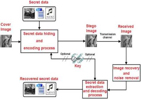
Figure 1. A block diagram of information hiding and steganography process
Many fragile steganography algorithms and techniques have been introduced and proposed in the past. Most fragile algorithms are simple but less robust than robust steganography algorithms. Fragile algorithms can be divided into two categories, namely adaptive and non-adaptive. In non-adaptive, in case of image steganography, modifications due to secret data embedding are uncorrelated with image features. On the other hand, in adaptive algorithms modifications are correlated with the image content (features). Most transform based algorithms which are commonly used for information hiding are adaptive in nature. As an example of such algorithm, in [7] data hiding is achieved using integer wavelet transform without distorting the cover image. This algorithm hides data into one or more middle bit-planes of the integer wavelet transform coefficients in the middle and high frequency sub-bands. Discrete Cosine Transform (DCT) on the other hand is another promising technique used for both data hiding and image compression [8]. Channel coding and modulation schemes such as turbo codes and convolutional codes using soft-decision decoding are also used for as steganography tools [9].
All the above mentioned algorithms do not directly modify the contents of an image or pixel values. On the other hand, some algorithms use direct methods to modify the contents of an image feature or pixel. Bit Plane Splicing LSB technique is an example of such algorithm used to modify the pixel value (gray level or color intensity) of an image pixel by pixel [10 – 13]. This technique is very efficient, simple and fast for information hiding inside the lower bit planes of an image. Low invisibility is the major drawback of this technique. As we increase size of secret data to be hidden, more planes of an image are used for data hiding and hence more degradation occurs in the visible quality of a cover image [10]. For this reason the perceptual transparency which is a requirement of a strong fragile steganography is poor for Bit Plane Splicing LSB technique. In addition, this technique is non-adaptive and treats each and every pixel in an image equally when it comes to secret data hiding. In this paper we have proposed a two modified versions of the Bit Plane Splicing LSB technique which are not only adaptive in nature but have more data capacity and better invisibility performance than the normal Bit Plane Splicing LSB technique.
The improvement presented in our work is not merely based upon the quality judgment of the stego image by human visual system but rather based upon a degradation information theory based parameter. This measuring parameter is called the Absolute Entropy Difference .
Rest of the paper is organized as follows: in section 2 an overview of the normal Bit Plane Splicing LSB technique and its performance is presented. Our first proposed algorithm called Optimum Intensity Based Distributed Hiding (OIBDH) is discussed in section 3 while the second proposed algorithm called Linear
Congruent Optimum Intensity Based Distributed Hiding with Key (LCOIBDH- k ) is explained in section 4. Test results of the proposed algorithms are presented section
-
5. Finally conclusion is made in section 6.
-
II. Bit Plane Splicing LSB Technique
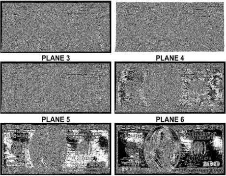
A gray scale digital image consisting of M × N pixels with each pixel is represented by г bits has a size of M × N × r bits. In case of r = 8, a pixel can have an integer value between 0 (black pixel) and 255 (white pixel) which represents the gray level intensity of a pixel. Furthermore, such an image can be split into 8 layers such that each layer is considered to be a separate image. For instance if the pixel intensity in an image is 200 for which the binary representation in 8 bits is 11001000, then the 8 planes of this pixel starting from the least significant bit or plane are 0, 0, 0, 1, 0, 0, 1, 1. In a similar manner for M × N size image, each plane is of size M × N as well with each plane considered to be a binary image. When combining these individual planes, we get the actual gray scale image. Fig. 2 demonstrates the plane distribution for Dollar gray scale image. It is evident that most of the data is contained inside the eighth plane and has a major contribution in building the original image. As we go towards the LSB plane, the information contained related to the original image decreases. In fact the lower half plane has less contribution in building the original image than the upper planes. We can also see that as we eliminate each plane starting from the LSB plane, degradation occurs more and quality of the image becomes poor. With a similar argument mentioned above, eliminating the lower half planes has less impact in quality degradation of the actual image than eliminating the upper half planes.
Based upon these facts the Bit Plane Splicing LSB technique for information hiding was introduced that hides information or secret bits in the lower bits by replacing the lower bits of pixels in the cover image with secret bits [11]. The replacement of bits takes place pixel wise in a sequential manner either horizontally or vertically. When a particular plane is fully replaced by secret bits the next immediate higher plane is accessed as elaborated in Fig. 3. Since the replacement takes place pixel wise this method does not differentiate between pixels’ attributes, sensitivity, location and intensity. It treats a pixel as a bundle of bits and thus the method is static in nature.
To further see what happens when each plane of the cover image is replaced by random bits, we perform a test on camera man image as shown in Fig. 4. In this test we replace each plane totally by random bits of size M × N bits . After each replacement, the image is displayed to see the impact of bit replacement on the quality of cover image. It is clear that till plane number two there is almost imperceptible degradation in the cover image. But beyond the second plane, degradation in the form of artifacts can be seen especially when fourth and fifth planes are accessed. This shows that
Bit Plane Splicing LSB technique has limited data insertion capabilities and degrades the cover image severely.
Generally, regardless of size and type of image, Bit Plane Splicing LSB technique has a hiding capacity not beyond the second plane. This puts a huge limitation over the implementation of this technique especially when the secret data is greater than two plane size of the cover image.
ORIGINAL IMAGE

To further evaluate the performance of Bit Plane Splicing LSB technique, we need to check its hiding capacity and the amount of degradation in the quality of cover image after data hiding process. As a general rule, quality degradation of the cover image is directly proportional to the size of secret data to be hidden. For this purpose we use Absolute Entropy Difference parameter as mentioned in [14] for image quality degradation measurement of this algorithm and our proposed algorithms.
It is well known that the entropy of an image f ( x , y ) is given as [15]:
Entropy =∑ Pt log 2 Pt
1=0
PLANE 1
PLANE 2
PLANE 7
PLANE 8

Figure 2. Contribution of the eight bit planes in constructing the original image
where Pt indicates the histogram or probability value of a particular pixel intensity in f ( x , y ) and l = 2 r is the total intensity values. In a similar manner, Absolute Entropy Difference is defined as the absolute difference of the entropy value of the cover image before data hiding and the entropy of the stego image after hiding a particular amount of data inside the cover image. Note that the size of an image has no effect on its entropy value whereas the probability of occurrence of the intensity levels of pixels has a major role in producing different entropy values.

Figure 3. Plane distribution and data insertion method in Bit Plane Splicing LSB technique
This concept is shown in Fig. 5 in Lena’s image. The image is of size 300 ×300 pixels and the intensity range is from 0 to 255. The figure shows that at level 0 (means when no modification is done on the image) the entropy value using (1) is around 7.2738 which is the maximum value. Now as we darken or brighten by a level (e.g. level 1 means all pixel intensities are increased by 1), entropy value decreases. Note that we have increased or decreased the intensity of each pixel by the same amount and truncated those intensity values out of bound (i.e. 0 and 255). It is evident that as we change the intensity of an image in this manner, the entropy value decreases till it becomes 0 (i.e. when all pixels are either black or white and the image conveys no information according to information theory). Similarly if we suppose that the secret data to be hidden is random in nature and assumed to be an external noise with a specific probably density function then as the size of the secret data increases, the absolute entropy difference also increases. In Fig. 6, the same camera man image is used to support this fact. In this case we have chosen the ‘salt-pepper’ noise as secret data which is inserted in the cover image. Fig. 6 (a) shows a low level noise and Fig. 6 (b) is a high level noise both inserted into the cover image for which the entropy differences are 0.0311 and 0.5116 respectively. This shows that more we insert data into the cover image, more changes occur in the entropy value of the cover image.
Plane 1 bits insertion Plane 2 bits insertion Plane 3 bits insertion Plane 4 bits insertion
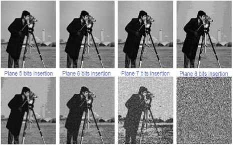
Figure 4. Image degradation due to Bit Plane Splicing LSB technique plane wise staring from plane 1 till plane 8
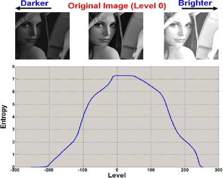
Figure 5. The impact of uniform intensity change on the entropy value of an image
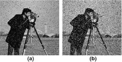
Figure 6. The effect of random noise insertion in an image on its entropy value
For Bit Plane Splicing LSB algorithm, entropy curve shown in Fig. 7 (f) is generated by calculating the original entropy of the cover image then after each data insertion (in bits) as indicated earlier pixel wise plane after plane in a sequential manner the entropy of the stego image is calculated after which the absolute entropy difference between both entropy values is calculated. The experiment is done on camera man image shown in Fig. 7 (a). Initially when there is no secret information the stego image is same as the original cover image and the absolute entropy difference is zero. Now as the size of secret data increases the absolute entropy difference also increases. Or in other words, the quality of the image degrades as the size of secret data to be hidden increases. Since the image size in bits is 256x 256 x 8 with 8 planes, the secret data size can have a value between 0 bits (i.e. no secret data) to 524288 bits (i.e. when secret data size is same as cover image size). Now to see the effect in the quality of image as the size of secret data varies, from Fig. 7 (f) we have selected 8 points from the curve corresponding to 8 different sizes of secret data indicated by red circles. These points correspond to the 8 planes of the cover image. For instance, the first secret data size is 256 x 256 x 1 = 65536 bits which means that the LSB plane or the lowest plane of the cover image is replaced by the secret data. Table 1 shows 8 entries of secret data sizes, the corresponding plane being replaced and the absolute entropy difference whereas Fig. 7 (b-e) shows four of the stego images resulted from replacing the second, third, fourth and seventh planes respectively. Visually we can clearly see that till plane 2 quality of the cover image does not degrade much and it is tolerable but as we move from plane towards the third plane, visual degradation especially in uniform intensity areas (e.g. sky) is evident as shown in Fig. 7 (c). Moving towards plane 4 as shown in Fig. 7 (d) i.e. when 50% of the data is hidden in the lower half of the cover image, extreme degradation occurs and the artifact effect is prominent even in dark areas (e.g. coat of camera man). Beyond plane 4 the image becomes unrecognizable. This experiment shows that generally speaking for Plane Bit Splicing technique, the maximum capacity of secret data to be hidden in a cover image is approximately between 25 to 35% of the cover image size. This range could slightly vary from image to image with different shades and intensity levels of pixels.
Beside the above mentioned degradation, another visual degradation occurs when the secret bits extend to partial areas of the plane due to its sequential insertion method. For instance assuming that the insertion takes place starting from the top left pixel and continues column wise, now if the cover image size is (600 × 600 × 8) bits and the secret data size is (600 × 600 × 2.5) then the visual degradation after hiding the secret data occurs more severely on the left half section of the stego image because the secret data spreads over the third plane on the left half of the image whereas secret data occupies the first two planes only for the right half section of the stego image. The overall impact results in a stego image with more visual degradation on the left side compared to the right side.
In summary although Bit Plane Splicing LSB technique is a very simple and easy method implementation wise for data hiding, but it has a major disadvantage in terms of its limited data hiding capacity due to quality degradation of the cover image. It results in an attacker monitoring the transmission to suspect a hidden object or data inside the cover image which might further trigger an unwanted and harmful action. Our proposed techniques handle this problem by reducing the degradation caused by hiding process which is discussed in the next two sections.
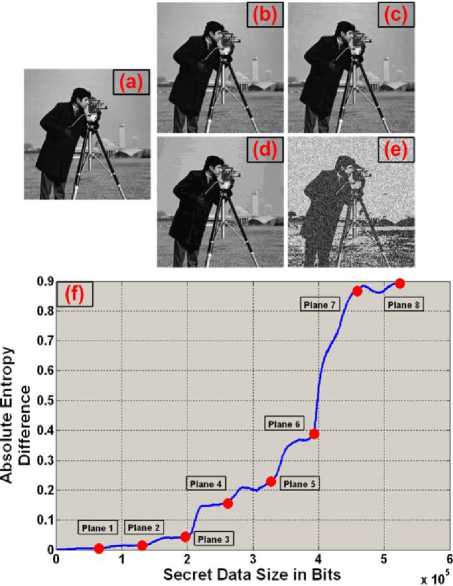
Figure 7. (a) Original cover image (b-e) Image degradation due to data hiding using Bit Plane Splicing LSB technique when data size equals to plane 2, 3, 4 and 7 respectively. (f) Entropy curve of camera man image when Bit Plane Splicing LSB technique is applied
-
III. The First Proposed Technique: Optimum Intensity Based Distributed Hiding (OIBDH) Technique
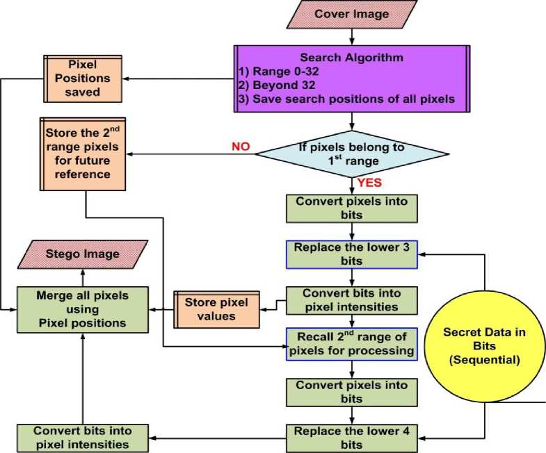
In this section we propose our algorithm called Optimum Intensity Based Distributed Hiding (OIBDH). In this algorithm as in case of Bit Plane Splicing LSB the lower bits are used to hide secret bits but now in a different manner. Instead of hiding bits pixel by pixel and plane after plane the bits are hidden based on the color intensity of a pixel. We have chosen two ranges of intensity levels. Assuming that l = 256 (i.e. 8 planes), for the intensity of pixels between 0 - 31, the lowest 3 bits are used for hiding secret bits where as for pixels having intensity of more than 31, only the lower 4 bits are used. By performing heuristic testing with different range of values and searching algorithms we have come up with this optimum range. This range is a near optimum range and causes least cover image degradation. This distribution is achieved based on pixel weight and its degradation severity (i.e. the human visual perception due to transition of pixel intensity from one level to another). In addition, since bright intensity levels are more sensitive when transition takes place and dark levels are less sensitive, we have chosen less number of bits for hiding in brighter pixels and higher in darker ones. Furthermore the method of hiding bits is different in case of OIBDH. In case of Bit Plane Splicing LSB a single secret bit and its very adjacent bit are hidden in adjacent pixels since the secret data are embedded sequential wise. But in case of OIBDH, if the first bit is hidden in plane q and in pixel w then the next bit is hidden in the same plane but in any pixel in the cover image and not necessarily in the adjacent pixel as the next pixel with same intensity value could be located anywhere in the image. In this way the secret data is distributed throughout the image based upon the color intensity of pixels which is random for every image. In addition, those pixels having intensity levels between 0 - 31 are used first for data insertion followed by the second range of pixels. Note that not only the bits are hidden randomly in pixels but also the planes are traversed in a non sequential manner and not plane by plane as in the case of Bit Plane Splicing LSB technique. To elaborate the steps through which the algorithm works, a flow diagram of the proposed algorithm is given in Fig. 8 at the sender’s end.
The proposed algorithm is reversible as the secret data is recovered properly. Note that we are assuming that the received image contains no noise or impairments due to transmission channel. In order to protect the stego image from channel induced interference, channel encoding and modulation techniques can be used along with error detection and correction codes but this is not the topic of this paper. For this reason we are assuming a perfect channel in order to explain the recovery process. The recovery process explained in Fig. 9 is same as the hiding process. Each pixel is inspected for its intensity value. If a pixel belongs to the first range, then the last three bits are extracted. This process continues till all the pixels in the first range are exhausted after which the second range of pixels are found and the lower four bits are extracted. It is clear that during hiding process and after inserting the secret bits, the intensity values of pixels change but the intensity range remains the same. In this way there is no need for an extra step to recover our secret data because the intensity range for pixels remains intact. Furthermore, to recover the secret data properly, the size of secret data should be transmitted or shared between the sender and receiver to make sure that false data is not extracted from those pixels which do not contain secret bits. The proposed technique outperforms the conventional Bit Plane
Splicing LSB technique as it generates less distortion in the stego image.
Although OIBDH performance which is discussed in section 5 has better performance than Bit Plane Splicing LSB technique, still it is predictable since statistical analysis can reveal the positions of hidden data [16]. In addition, since the embedding method is always known to everyone, an unwanted party can easily find the sequence of the hidden data by applying the recovery process. To tackle this problem, an extension to this technique is proposed which has better security features as well as being more efficient in terms of data hiding capacity. This extended version of OIBDH is discussed in the next section.
YES
Stego Image
Secret Data in Bits (Sequential)
pixels belong to 1st range
IPixel I Positions saved
Cover Imai
NO
Store the 2nd range pixels for future reference
Search Algorithm
1) Range 0-32
2) Beyond 32
3) Save search positions of all pixels values
Convert bits into pixel intensities
Recall 2nd range of pixels for processing
Merge all pixels using Pixel positions
Convert pixels into bits
Replace the lower 3 bits
Replace the lower 4 bits
Convert pixels into bits
Convert bits into pixel intensities
Figure 8. Flow diagram of the proposed OIBDH algorithm at the sending end
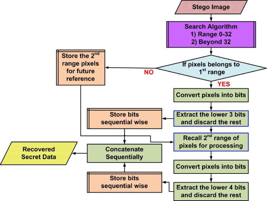
Figure 9. Flow diagram of the proposed OIBDH algorithm at the receiving end to recover the hidden secret data
-
IV. The Second Proposed Technique: Linear Congruent Optimum Intensity Based Distributed
Hiding with Key (LC-OIBDH-k) Technique
In order to make OIBDH more secured while maintaining its data hiding capabilities, we propose a different embedding method which is same as OIBDH but with one more extra rule. This extra rule not only adds more security in the overall system but also has a better hiding performance than OIBDH. The process stars as follows: firstly we select some parameters to generate two levels of random numbers. The first level of parameters is used to generate numbers which indicate the sub-column widths of the cover image. Or in other words, the cover image is divided into sub areas or sections with different column sizes. So if the column width of the cover image is N and if we select an initial seed value say k (which we also call it a secret key) as our starting point for further calculation, then using uniform distribution with equal probability a single random number is generated with k as an initial seed from a pool of numbers between 1 and d such that d < N. In each iteration the generated number will be a random number between 1 and d. These random numbers act as column width of each sub-group generated by this process. For the first sub-group, the column width equals to the initial seed value i.e. k. For subsequent sub-groups, the column width is generated using the same process described earlier but the initial seed for the random function generator takes the value of the previous sub-group column width. If the random function generator is indicated by F and the generated numbers by Xi where ‘i’ is the generated sub-group index number, then this iterative process can be expressed as:
pl = k
|x ^'([WU J
first subgroup subsequent subgroups such that the two parameters inside the function F are the selection range and the seed number. Furthermore, the total number of generated sub-groups varies depending upon the values of d and k. In addition after each iteration, the column width of all previous subgroups is subtracted from the cover image width N. If the remaining available width after subtraction is larger than d, then the sub-group width iteration continues otherwise the remaining available width becomes the current sub-group width and this will constitute the last sub-group. This forceful condition of width generation for the last sub-group is imposed because the random function can generate a value greater than the remaining available width to be allocated to the current sub-group.
For instance, if the M = 40, N = 40, d = 19 and k = 6, and assuming that the total number of sub-groups is T , then the generated sub-group widths are given as below using uniform random number generator with equal probability of occurrence and initial seed value k :
-^ х2 х3 х4 х5 х6
6 1 18 7 5 3
Note that T = 6 and the width of the last sub-group i.e.
sub-group 6 is calculated as N - sum ( X 1 ^ X 5 ).
Fig. 10 illustrates sub-group generation for the previous example. Each square in Fig. 10 represents a pixel of an image with size 40 × 40 and pixels of the same shade belong to same sub-group having a width of X i where i = 1,2,_,6.
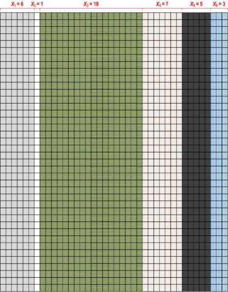
Figure 10. Sub-group creation of an image with size 40 × 40 using k and d as generation parameters in LC-OIBDH- k proposed technique
Secondly in level two and after generating the subgroups, columns of subgroups are indexed in a random manner using linear congruent random number generator [17]. According to linear congruent method, random numbers are generated between 0 and an upper limit upon using an initial seed. For each sub-group, a separate random column indices are generated using linear congruent function. Initially for each sub-group d number of indices is generated using linear congruent method such that the first index of a column for any subgroup has a value equals to X i . In addition, these generated d indices are right circular shifted by an amount equals to ( X i + X T - i +1 ) positions sub-group wise. Finally, amongst these d circular shifted values, first X i indices are selected and the rest are discarded.
Assuming that a general term for any of the d indices in a sub-group Gi is indicated as hi,j where the pair i,j represents the column index j in the ith sub-group with i = 1,2,...,T and j = 1,2,...,d , then the following expressions generate the final indices for columns in each sub-group:
{ℎ , = 1
ℎ , =[( ×ℎ , )+ ] ℎ
where s and c are parameters of the linear congruent random number generator and i = 1,2,..., T and j = 2,3,..., d . Note that h 1,1 is the starting point for the recursive calculation which is always equals to the secret key k .
Once the random column indices for T sub-groups are generated using (3), namely d indices in each sub-group, right circular shift is applied on each sub-group G i by ( X i + X T — i + 1 ) positions. After the circular shift, the first X i numbers are selected from the respected sub-groups. As a result, the new indices width for each sub-group equals to X i which is the final desired indexing. The final random numbers in a particular sub-group Gi after applying the two steps mentioned above can be shown as:
[ , , , ,…, , ,… , , ]
=[ℎ , ,ℎ , ,…,ℎ ,
ℎ , ,ℎ ,
…,ℎ , ]
ℎ =( ) , =1,2,… =1,2,… , (4)
Here z i,l indicates the new and final indexing for the columns in a sub-group. Fig. 11 shows the flow diagram of sub-group indices generation.
As a completion of the previous example, the complete d generated indices for each sub-group, the shifted version of these d generated indices and the final selected indices i.e. z i,l are shown in Fig. 12 (a,b,c) respectively. Note that indices of any sub-group G i are shown row wise. For the above previous mentioned example, the amount of shifts applied on the indices of each sub-group are [9, 6, 25, 25, 6, 9] respectively.
Upon identifying the column indices per sub-group, the process of hiding takes place in the same manner as in OIBDH. The same two rules are used as in OIBDH for data hiding per pixel. The only difference is that instead of hiding data in pixels by ordered sequential value, data is hidden column wise per sequential indices order. For instance, if the indices of a sub-group with 6 columns is given as [12, 5, 20, 27, 5, 2], then the data is hidden in the last column first as it has the lowest index followed by the two columns with index value of 5 in an ordered manner. Then the data is hidden inside pixels belonging to columns 12, 20 and 27 respectively. Note that, within a column, data is hidden again in the same manner as in OIBDH (i.e. pixels belonging to the first range are accessed first followed by pixels belonging to the second range). Once bits are hidden inside particular sub-group pixels, the next sub-group pixels are accessed for data hiding. The process moves from one sub-group to another till all secret bits are hidden.
It is worth mentioning here that this whole process randomly hides information depending upon the secret key or initial seed which is shared between the authentic users only. Hence, even if a third unwanted entity has knowledge of the algorithm, the hidden data cannot be extracted without the key. Furthermore, in order for the data to be recovered properly, k, s, c and d parameters are to be shared as secret parameters. Using these parameters at the receiving end, the entire sub-group column indices are regenerated and accordingly the bits are extracted from pixels.
-
V. Performance Evaluation of the Proposed Techniques
To compare the performance of our proposed techniques with LSB technique, a series of experiments are performed. In the first experiment Bit Plane Splicing LSB and OIBDH techniques are applied on a test image containing all the gray scale shades between 0 and 255 shown in Fig. 13 for which the same secret data is used for hiding. The purpose of this experiment is to see the transition of gray shades and it’s severity for both techniques. As it is evident from Fig. 13 (b) and (c), the degradation is more severe using Bit Plane Splicing LSB technique than in OIBDH especially in the gray region near darker side. Also note how the transition of gray levels changes abruptly in LSB technique and less abruptly in OIBDH. This shows that hiding data based on pixel intensity level results in less degradation of the cover image compared to Bit Plane LSB technique.
Furthermore, to compare the performance of all the techniques in terms of absolute entropy difference curves, the algorithms are applied on camera man image with different secret data sizes as shown in Fig. 14. The cover image in this case is the camera man image shown in Fig. 7 (a) having size of 256 × 256 × 8 = 524288 bits and its calculated entropy value using (1) is 7.1048. In addition, it has to be noticed that the maximum secret data size or cover image capacity in case of Bit Plane Splicing LSB technique is 524288 bits and 210000 bits in case of OIBDH and LC-OIBDH- k which is less than that of Bit Plane Splicing LSB technique. This is obvious because of the two rules imposed on pixels when OIBDH or LC-OIBDH- k is used. In addition, two sets of curves are generated for LC-OIBDH- k , the first having the following parameters: d = 63, c = 10, s = 22 and k = 6, and the second having the following: d = 100, c = 17, s = 32 and k = 40. The comparison is conducted till secret data size of 210000 bits as data size larger than this size is not allowed for the proposed techniques in this image and hence not shown in the figure. From these curves it is evident that the absolute entropy difference values of the proposed techniques are smaller than their counterparts for Bit Plane Splicing LSB technique for the same amount of secret data. This result implies that less degradation occurs on the cover image when using the proposed techniques than Bit Plane Splicing LSB technique.
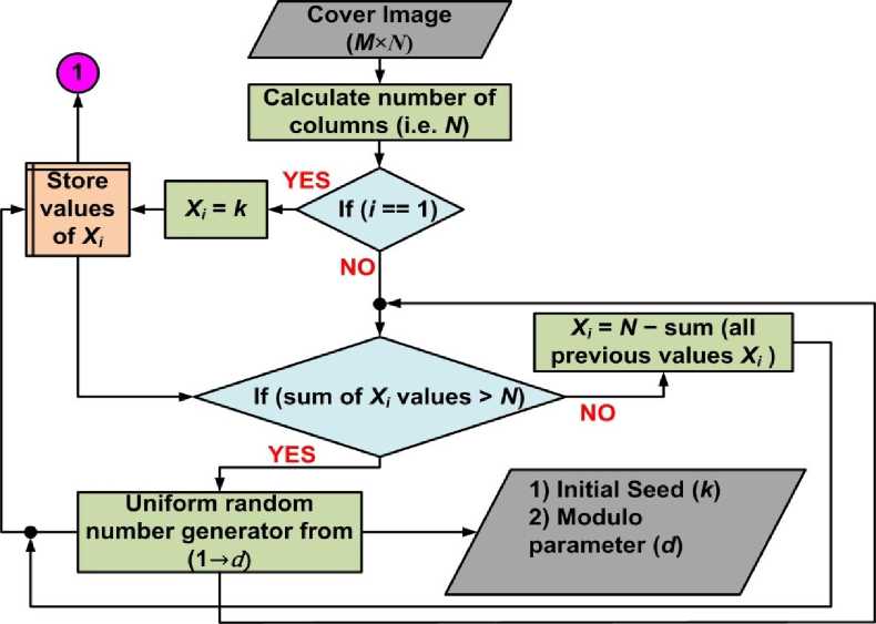
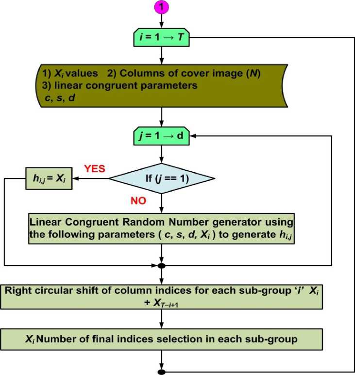
Figure 11. Flow diagram of sub-group generation and column indices generation for the sub-groups
G4 = [06 10 03 01 14 15 18 08 16 02 17 05 07 13 12 09 19 1106]
G2 = [01 14 15 18 08 16 02 17 05 07 13 12 09 19 11 06 10 0301]
G3 = [18 08 16 02 17 05 07 13 12 09 19 11 06 10 03 01 14 1518]
G4 = [07 13 12 09 19 11 06 10 03 01 14 15 18 08 16 02 17 0507]
Ge = [05 07 13 12 09 19 11 06 10 03 01 14 15 18 08 16 02 1705]
Gg = [03 01 14 15 18 08 16 02 17 05 07 13 12 09 19 11 06 1003]
(a)
G, = [17 05 07 13 12 09 19 11 06 06 10 03 01 14 15 18 08 1602]
G2 = [19 11 06 10 03 01 01 14 15 18 08 16 02 17 05 07 13 1209]
G3 = [10 03 01 14 15 18 18 08 16 02 17 05 07 13 12 09 19 1106]
G4 = [08 16 02 17 05 07 07 13 12 09 19 11 06 10 03 01 14 1518]
G5 = [18 08 16 02 17 05 05 07 13 12 09 19 11 06 10 03 01 1415]
G6 = [07 13 12 09 19 11 06 10 03 03 01 14 15 18 08 16 02 1705]
(b)
G, = [17 05 07 13 12 09]
G2 = [19]
G3 = [10 03 01 14 15 18 18 08 16 02 17 05 07 13 12 09 19 11]
G4 = [08 16 02 17 05 07 07]
G5 = [18 08 16 02 17]
G6 = [07 13 12]
(C)
Figure 12. Column indices of sub-groups for an image of size 40 × 40 using Xi , k , s , c and d as Linear congruent random number generator parameters in LC-OIBDH- k proposed technique (a) d indices in each sub-group (b) Right circular shifted of the d indices (c) Final X i indices selection in each sub-group
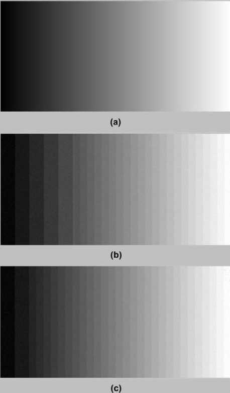
Figure 13. (a) Image degradation of gray intensity transition image when: (b) Bit Plane Splicing LSB technique is applied (c) OIBDH is applied
Now comparing the performance of OIBDH with LC-OIBDH- k , it is clear that the latter with both sets of parameters have lower absolute entropy difference values than OIBDH especially the second set of parameters based curve. Again this shows that the modified version of OIBDH has the best performance amongst the mentioned techniques with better security performance than OIBDH.
Finally to have a visual look on the quality degradation of cover image for all the techniques, Lena’s image shown in Fig. 15 (a) is used. The maximum capacity when OIBDH or LC-OIBDH- k is used is 287689 bits whereas cover image size is 720000 bits. Stego images corresponding to secret data size of 287689 for Bit Plane Splicing LSB technique, OIBDH, LC-OIBDH- k with first set of parameters and LC-OIBDH- k with second set of parameters are shown in Fig. 15 (b, c, d and e) respectively. It is not difficult to see the degradation caused by Bit Plane Splicing LSB technique in the overall image specially the resulted artifacts in uniform gray areas e.g. shoulder and cheeks in Fig. 15 (b). These degradation areas are reduced considerably using the proposed techniques. Note that LC-OIBDH- k has better performance than OIBDH whereas the difference between the stego images obtained by LC-OIBDH- k with the two parameters cannot be perceptible as shown in Fig. 15 (d and e). In fact the image quality of the stego images after using the proposed algorithms and the original cover image is very minimal and cannot be discriminated.
-
VI. Conclusions
In this paper two algorithms called Optimum Intensity Based Distributed Hiding (OIBDH) and Linear Congruent OIBDH with key (LC-OIBDH- k ) are proposed for secret data hiding inside pixels of a cover image. OIBDH technique is an improved version of Bit Plane Splicing LSB technique where secret data are not hidden sequential wise and plane by plane as in Bit Plane Splicing LSB technique. Rather data are hidden in a non-sequential manner and not plane by plane. The amount of bits to be hidden in a pixel depends on the gray scale value of the pixel. This makes the proposed algorithm dynamic in nature and more effective both in terms of data hiding capacity and visual degradation of the cover image than Bit Plane Splicing LSB technique. In addition, to add more security to OIBDH, LC-OIBDH- k is proposed which uses a secret key or an initial seed to generate sub-groups with random column width and indices using linear congruent random number generator. Secret bits are hidden according to these indices column wise and following the same rules of OIBDH for data hiding. Results obtained in the form of absolute entropy difference curves and visual degradation of various cover images show that LC-OIBDH- k not only has better hiding performance than OIBDH but also exhibits better security as the secret key is only known and shared between trusted users.
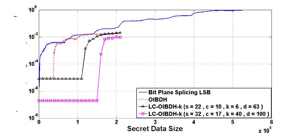
Figure 14. Absolute entropy difference curves of Bit Plane Splicing LSB technique and the proposed techniques
Absolute Entropy Difference (in log scale)
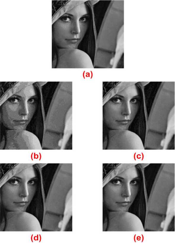
Figure 15. Quality Degradation of (a) Cover image when the following techniques are applied (b) Bit Plane Splicing LSB technique (c) OIBDH (d) LC-OIBDH- k with first set of parameters (e) LC-OIBDH- k with second set of parameters
Acknowledgment
This paper is fully supported by the Department of Computer Engineering, Sir Syed University of Engineering and Technology.
References Improved Bit Plane Splicing LSB Technique for Secret Data Hiding in Images Using Linear Congruent Method
- Dapeng Wu, Yiwei Thomas Hou, Wenwu Zhu, Ya-Qin Zhang and Jon M. Peha, “Streaming Video over the Internet: Approaches and Directions”, IEEE Transactions on circuits and systems for video technology, vol. 11, no. 3, pp. 282 – 300, 2001.
- I. J. Cox, M. L. Miller, J. A. Bloom, J. Fridrich and T. Kalker, “Digital Watermarking and Steganography”, 2nd Edition., Morgan Kaufmann Publishers, Massachusetts, California, 2008.
- R.J. Anderson and F.A.P. Petitcolas, “On the Limits of Steganography” J. Selected Areas in Comm., vol. 16, no. 4, pp. 474 – 481, 1998.
- Sung A.H., Tadiparthi G.R. and Mukkamala S., “Defeating the current steganalysis techniques (robust steganography)”, in proc. of The International Conference on Information Technology: Coding and Computing (ITCC 2004), Las Vegas, Nevada, USA., pp. 440 – 444, 2004.
- Chiou-Ting Hsu and Ja-Ling Wu, “Hidden Digital Watermarks in Images”, IEEE Transactions on Image Processing, vol. 8, no. 1, pp. 58 – 68, 1999.
- Soumik Das, Pradosh Bandyopadhyay, Shauvik Paul, Atal Chaudhuri and Monalisa Banerjee, “An Invisible Color Watermarking Framework for Uncompressed Video Authentication”, International Journal of Computer Applications, vol. 1, no. 11, pp. 22 – 28, 2010.
- Guorong Xuan, Jiang Zhu, Jidong Chen, Shi, Y.Q., Zhicheng Ni and Wei Su, “Distortionless data hiding based on integer wavelet transform”, Electronic letters, vol. 38, no. 25, pp. 1646 – 1648, 2002.
- Faisal T. Alturkia, Ali F. Almutairib, and Russell M. Mersereauuc, “Analysis of blind data hiding using discrete cosine transform phase modulation. Signal Processing: Image Communication”, vol. 22, no. 4, pp. 347 – 362, 2007.
- Chou, J. and Ramchandran K., “Robust turbo-based data hiding for image and video sources”, in proc. of IEEE International Conference on Multimedia and Expo 2002 (ICME '02), Lausanne, Switzerland, pp. 565 – 568, 2002.
- Sandipan Dey, Ajith Abraham and Sugata Sanyal, “An LSB Data Hiding Technique Using Prime Numbers”, in proc. of the Third International Symposium on Information Assurance and Security (IAS '07), Manchester, United Kingdom, pp. 101 – 106, 2007.
- Chi-Kwong Chan and L. M. Cheng, “Hiding Data in Images by Simple LSB Substitution”, Pattern Recognition, vol. 37, no. 3, pp. 469 – 474, 2004.
- Cheng-Hsing Yang, Chi-Yao Weng, Shiuh-Jeng Wang and Hung-Min Sun, “Adaptive Data Hiding in Edge Areas of Images With Spatial LSB Domain Systems”, IEEE Transactions on Information Forensics and Security, vol. 3, no. 3, pp. 488 – 497, 2008.
- Cheng-Hsing Yang, “Inverted pattern approach to improve image quality of information hiding by LSB substitution”, Pattern Recognition, vol. 41, no. 8, pp. 2674 – 2683, 2008.
- Keiji Yanai and Kobus Barnard, “Image region entropy: a measure of "visualness" of web images associated with one concept”, in proc. of the 13th annual ACM international conference on Multimedia, Singapore, pp. 419 – 422, 2005.
- Norman Abramson, “Information Theory and Coding”, 1st edition, McGraw-Hill Education, 1963.
- Andrew D. Ker, “Steganalysis of LSB matching in grayscale images”, IEEE Signal Processing Letters, vol. 12, no. 6, pp. 441 – 444, 2005.
- P. Hellekalek, “Good random number generators are (not so) easy to find”, Mathematics and Computers in Simulation, vol. 46, no. 5, pp. 485 – 505, 1998.
