Improving Quality of Service of Femto Cell Using Optimum Location Identification

Author: Seetaiah Kilaru, Aditya Gali
Journal: International Journal of Computer Network and Information Security(IJCNIS) @ijcnis
Article in issue: 10 vol.7, 2015.
Free access
To enhance the throughput and Quality of Service (QoS) of indoor users, Femto cells became the best solution. The placement of a femtocell is always a challenging task due to its interference constraints with other cells. If the base stations has limited number of Femto-cells, then there is need to focus much on interference constraints. In the dense countries like India, there is a need to install more number of Femto-cells to get the proper throughput. But, the limiting factor here is frequency and interference management. This paper explained the interference management issues and hand over issues. This paper proposed method of optimal placement of Femto cell to increase the QoS in dense environment where macro-cell holds many number of Femto cells. This solution made an assumption that the interference effect was considerably strong when compared to Noise. Hence, we have not considered Noise parameter in the analysis. It was shown that the optimal placement has better throughput when compared to blind placement. Two cases were considered as blind placements and their throughput was analyzed with respect to optimal placement. The proposed method was tested in both single and multi-room buildings. Finally, it was observed that the gain of 50% was increased with respect to large buildings with many rooms.
Femto cell, Quality of Service, throughput and interference
Short address: https://sciup.org/15011463
IDR: 15011463
Text of the scientific article Improving Quality of Service of Femto Cell Using Optimum Location Identification
Published Online September 2015 in MECS DOI: 10.5815/ijcnis.2015.10.04
In recent years, it is observed that homogeneous cellular networks are converting into heterogeneous cellular networks by placing several microcells. The main reason behind this one is to increase the efficiency of the system in poor coverage area [7,8]. There are various types of techniques were available to install microcell in macrocell (base station) region. Femto cell is one of the interesting topics and is an example of microcell. They are specially designed for indoor coverage applications. The success factor of femtocell can be observed with throughput. Throughput depends on handling of interference issues. Especially, in indoor region, we can expect more than 50% of cellular traffic. Hence, handling interference between femtocell and macro cell is always a challenging task. There are various possibilities with respect to interference issues. i.e
-
1. Femto cell access point to other Femto cell access point within cell
-
2. Femto cell access point of one cell to Femto cell access point of adjacent Femto cell
-
3. Femto cell access point to other near macro cell.
Inter cell coordination is required to resolve the interference issues. Lack of control on femto cells by the service vendors is the main consideration in handling interference [1]. Placement of this femtocell is a key phenomenon here. Optimization should be achieved for better throughput and efficiency. D.Stamatelos and A.Ephremides were explained about the optimal placement of a wireless node to achieve high throughput. A.Pais et al. proposed method for successful cancelation of interference in micro cells. These two approaches focused on iterative computational techniques. This approach cannot be suggested for home applications and also for small enterprise locations. This is also not the practically distributed system. An active research is going on the optimal placement of Femto cell access point.
This paper is going to explain about the issues of optimal placement of an access point to get maximum throughput using Self Organizing Network. The efficiency and throughput network are the dependent on other network parameters. Hence, if we change any one network parameter, it replicates the effect on system throughput. Hence, we may call the network parameters are the functions of any throughput analysis. This paper focused on optimal regional selection in the indoor region. The proposed solution is independent of radio resource management techniques and signal processing. Initially, we calculated the expression for closed form Signal to Interference ratio for an indoor user. This observation will conclude about the situations of worst cell-edge throughput. Based on this expression, we can finalize the optimum placement of the femtocell.
-
II. Qos CHALLENGES
QoS maintenance is always a challenging ask in Femto Network due to close vicinity of many femtocell access points. In regular macro cell environment, interference issues will be solved with existed mechanisms. If we introduce femtocell in macro-cell area, we have to address severe interference problem. Interference may exist between macro-cell and femtocell or Femto-cell to Femto-cell or both [9,11,20]. QoS also depends on proper addressing of all possible interferences. The following are the various factors which influence the QoS. They are
-
• Hand off process
-
• Operating frequency
-
• Frequency management
-
• Security assurance
-
• Interference management
-
• Allocation of resources
-
• Provision of Backhaul network.
We can discuss in detail about some of the important parameters which can affect the performance of QoS [10,16].
Interference management
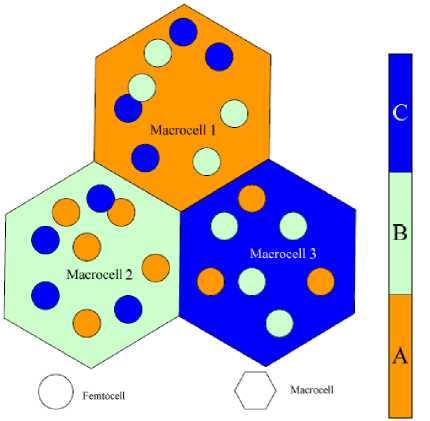
Fig. 1. Ideal frequency allocation to avoid interference
Conventional frequency allocation will not allow the network provider to increase the capacity. Hence, all modern network operators are shifting to dynamic frequency allocation which reduces the interference in macro environment. Cell edge users can experience more interference than the users who are near to cell. This is also true for Femto environment. Hence automatic frequency planning is required to minimize the interference [15,20,9]. If macro cell dedicates a channel to the femtocell user which is not in the frequency band of base station, we may reduce the interference between macro cell and Femto cell. This solution is only possible by maintaining the additional channels. It decreases the spectral efficiency of network and increase the cost. Hence sharing of existed channel between these two cells is an ultimate solution to increase the spectral efficiency [10].
This solution is suitable only for the base stations which has limited number of Femto cells. If the base station has to operate more number of Femto cells, traditional re-use scheme with re use factor 3 and above is the best solution as shown in figure 1.
From the figure 1, it is observed that, there are three frequency sub-bands A, B and C. Three micro-cells assigned with three sub-bands (one sub-band for each). Let us consider Macro cell 1 was assigned with frequency band A. Now, if the Femto cells under that sub-band use the same frequency band of A, there should be interference between macro-cell and Femto-cell. Hence, in order to avoid this, Femto-cells in that micro-cell 1(which has A frequency band) should use the frequency bands of micro-cell 2 and 3. With this we can reduce the interference problem between micro and Femto cell.
The following figure 2 shows the outage probability under the conditions of
-
• Same frequency band is allocated to micro-cell and Femto-cell [12,13,19]
-
• Different frequency bands are allocated micro-cell and Femto-cell.
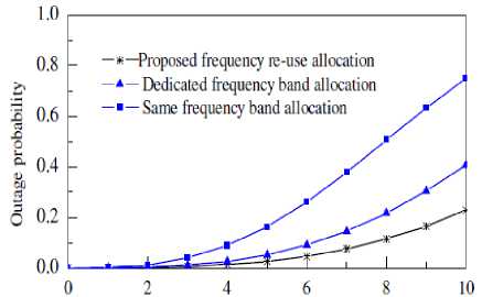
Fig. 2. Outage probability Vs frequency allocation (between micro cell and Femto cell)
This observation obtained from placing 1000 Femto cells under 1 micro cell. This graph indicates that the outage probability is very high if we assign same frequency band to both micro-cell and Femto-cells and it is very low for the vice-versa case [13, 15, 18].
If the densities of the Femto-cells are increasing under particular micro-cell, the probability of assigning same frequency band to the neighboring femtocell was also increases. This setup results inter Femto-cell interference which can degrade performance of the system [17]. Hence advanced interference management and mitigation techniques are required to achieve considerable QoS
Handover Control
The size of the Femto-cell is very small when compared to the micro-cell. Hence, there should be a frequent hand-off’s between Femto-cell to Femto-cell and Femto-cell to macro-cell. We should make a connection before breaking in these scenarios. On considering whole cellular system with Femto-cell, we can expect four types of interferences. They are
-
• Macro-cell to Macro-cell
-
• Macro-cell to Femto-cell
-
• Femto-cell to Femto-cell
-
• Femto-cell to Macro-cell
Hand off process involves with packet loss, delay, jitter and many other sensible parameters [10]. Consider an environment with a possibility of moderate/high concentration of Femto-cells. This set up requires careful evaluation and management of hand off which is most efficient than the existed hand off process. The following figure 3 shows this defined set up.
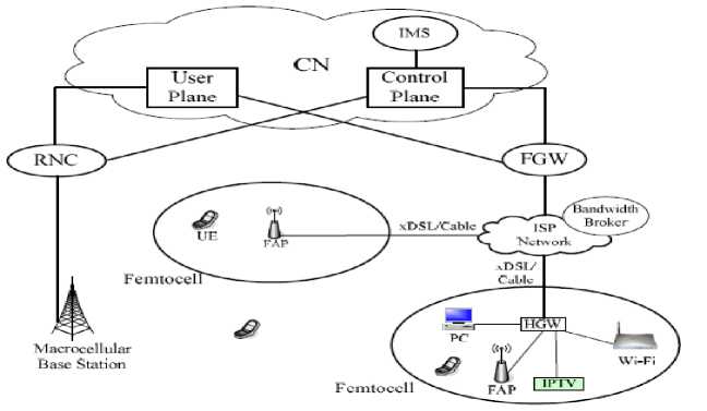
Fig. 3. Deployment of Femto-cells in Macro cell environment
The following figure 4 represents high dense environment with many Femto-cells.
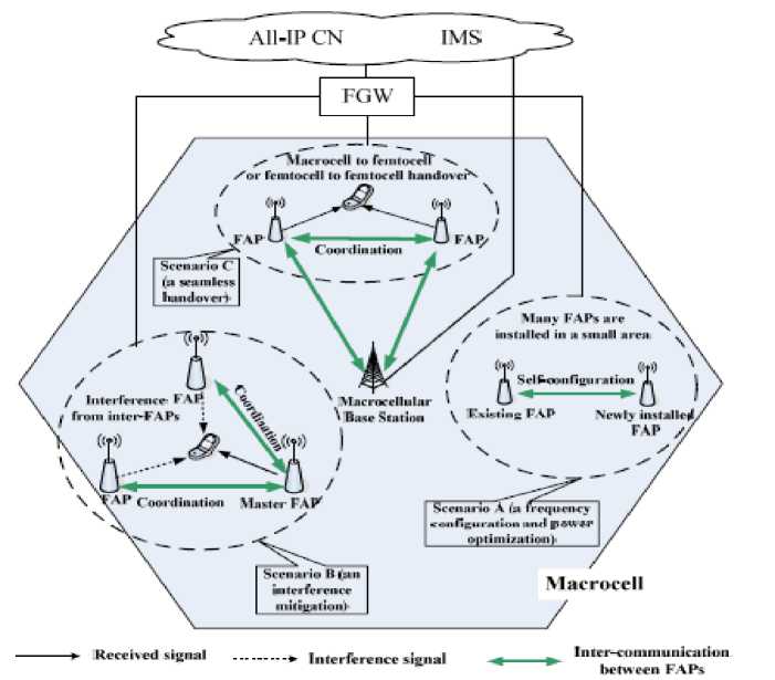
Fig. 4. Dense deployment of Femto cells
Hand over between Femto-cell and macro-cell in this environment is a challenging task. Every macro-cell has many Femto-cells and it becomes great difficulty for the base station to make hand off simultaneously with these Femto-cells [17]. The following figure 5 shows the efficient mechanism to deal with hand off. This experiment will reduce the number of scans of Femto cell
Access Points (FAP) [16,18]. When end user receives signal from neighboring FAP, it sends the information to the macro-cell base station. Now, base station will record the current position of Femto-cell, neighbor cells and their signal strengths. Then, base station will provide the authorized Femto-cell list to end user. This process reduces the scan off mechanism of all FAP’s.
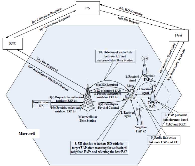
Fig. 5. Call flow procedure between Femto-cell and Macro-cell
The above procedure requires the lot of complexities which involves macro-cell control over Femto-cell, proper selection of FAP set and fast fading. Hand off is also creates a problem when there are fast moving vehicles in this region.
Hence, all these proposed and existed methods are not providing ideal situation with respect to transmission and handling interference. In this paper, we tried to explain the ideal of optimum placement of Femto-cell which can overcome some of the above defined problems [20].
-
III. Design Setup
The efficiency and performance of the network depend on maximum throughput for maximum users. It cannot define with mean throughput. If the femtocell gives this maximum throughput for all users, then we can conclude that the Quality of Service (QoS) of the network is high. In this design constraint, we are assuming OFDMA environment [2]. Uplink and downlink QoS optimization is a crucial task. This paper describes how to optimize downlink QoS also [6]. As the other design parameter, consider femtocell access point is placed in a single floor building and there is a dominant interference from other sources (may be a femtocell or surrounding base station or both).
To find the optimal location, as a designer we have to consider many factors like multipath propagation, building parameters and interference issues. The following figure shows indoor Femtocell Access Point (FAP).
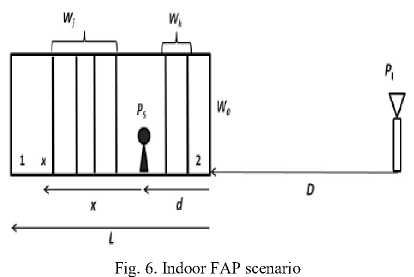
From the figure 6, we can define the following constraints:
-
1. Transmit power =P s
-
2. Maximum channel interference cell power =PI
-
3. Distance between edge of primary cell and the interference cell =D
-
4. Length of FAP placement construction = L
-
5. Distance between Femtocell and the last wall of construction = d
-
6. Distance between user and FAP = x
-
7. Any building wall which allows Electro Magnetic (EM) signals, should have penetration loss and consider it as W 0
-
8. All indoor walls also produce the loss to EM signal. Hence, we should take this factor also into consideration. Assume, this indoor path loss as W
-
9. The resultant pass loss of all walls from right side of FAP = W k
-
10. The resultant pass loss of all walls from left side of FAP = W j
-
11. Total indoor loss = ^in
-
12. The set up followed the consideration of D>>L
in
-
III. Optimization Constraints
For this analysis, consider the Signal to Noise Ratio (SNR) for the user x who located at the distance d from the FAP and is given as
For a defined location x, the user quality of service can be obtained from throughput and it is calculated as
c ( x ) =min( log ( l+y), Q) (4)
In practical scenarios, the effects of interference and multipath creates disturbance to the signal and hence the throughput can be modified as
c ( X )= ------------. ( x+d ) (5)
log(2) Pinout ( D+x+d ) -«outwoWk10 20
Optimization constraints
From figure 6, we can draw a conclusion that the downlink throughput parameter affects the Quality of Service (QoS). To increase the overall QoS, we have to maintain the throughput levels at locations 1 and 2 should be same. Let us consider there are M+ 1 equally spaced room in a floor. Let us assume that the Additive White Gaussian Noise (AWGN) factor was negligible when compared to interference strength [5]. Hence,
. м Ps^s^inx a^nWj
Y ( x )= x+d
PlH{K0Ut ( D+X+d ) -«out W0WjWk 10 20
log2(1+ Y ( x = - d ∗, £i)=log2(1+ Y ( x = ∗, £2 )
Consider that, the interference effect is significant when compared to Additive White Gaussian Channel (AWGN). Multipath fading and log-normal fading factors were considered in defining the probability density function (PDF) of the interference and is given as fH (S, ̃, ̃)= ̃√ = 6 ((loga-̃ )/2^ (2)
El ( L - d ∗) 2 ( "L ) D + L
( ∗ ) = 10 (20) ( + )
d∗= l+ra
। aout
This optimization achieved by the assumption of interference domination over noise and AWGN was neglected.
Where
From the above analysis, the combined distribution of interference and signal is given as [3]
E*5+= e°. 48 (^т^^ои^^)
For different locations, we can identify different distribution functions. The design parameters are shown in table 1.
Table 1.Design constraints
|
Design parameter |
Symbol |
value |
|
Indoor walls |
M |
7 |
|
frequency |
f |
2500-2600 MHz |
|
Loss exponent (Indoor) |
, |
1.69 |
|
Loss constant (Indoor) |
, |
7.76*10 "5 |
|
Building length |
L |
30 m |
|
Distance to create interference effect |
D |
100-500 m |
|
Loss exponent (Outdoor) |
aout |
3.67 |
|
Loss constant (Outdoor) |
^out |
0.000048 |
V=(7W^ ) ⁄ “inNLOs(7)
And n=10( ⁄20а^л)․(1+ )«tn(8)
If the deployment site belongs to large building and if it has number of rooms, then the parameter W can be defined as d (M+l)
Wk =10 (9)
From the above considerations, the optimal location can be given as d ∗(M)= (10)
l+^n^LQS
For example, if the room has only one wall then d∗(1)
L l+^NLOS
This was computed using simulations and following results describes single room and multi-room building calculations.
For simulation purpose, the required constraints were assumed as
Length of the building = 250m
Estimation of error = 5% to 95%
-
IV. Results
The following simulation result shows the optimal location placement of femtocell in 250m length building.
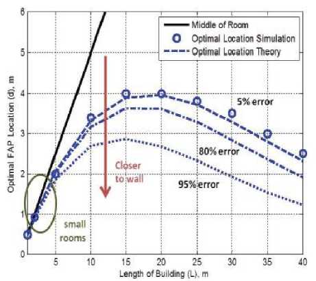
Fig. 7. Optimal location measurement for building which has only one room
-
• If the distance estimation is not proper regarding interference source, this proposed system results in less error in the solution. From the above figure, we can tell that 50% approximated error in theory results just 6% measured error in practice.
-
• Throughput depends on many factors like wall penetration, the distance between femtocell and interference source and also on the length of building.
-
• The solution of optimum placement was independent of transmitted power.
Let us consider the two locations of deployment regions; they are the corner of building and center of building. The following simulated plot shows the improvement in throughput when compared to defined cases.
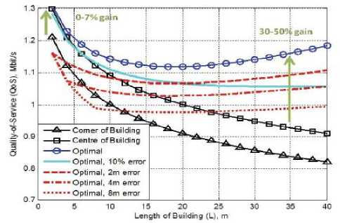
Fig. 9. Existed Vs Optimal QoS analysis
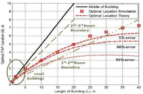
Fig. 8. Optimal location measurement for the building which has many walls
In every case, it is not possible to place the femtocell in proposed optimal location format. Due to many reasons, it may not possible and hence we are defining here the acceptable margin. This marginal change will not degrade QoS in an effective way. The results showed that, 10% optimal error is acceptable with respect to standard location.
From figure 9, it is clear that QoS is excellent with optimal allocation method when compared to the conventional method (place base station at middle of room/ towards wall). The gain difference between placement at centre of building and placement with optimum allocation method is 30-50%. This variance depends on many local characteristics.
From figure 7, it is clear that for a building which has only one room will get high error percentage with respect to middle of the room. If we follow the proposed methodology, error rate will be reduced to 5% from 95%. From this analysis it is clear that, the proposed method shows drastic change when compared to traditional method.
Even this method is applicable to a building which has many rooms. From this analysis, we can draw the following conclusions.
V. Conclusion
This paper discussed about the interference management of macro-cell with several Femto-cells. It also discussed about various hand off issues between Femto-cell to Femto-cell and Femto-cell to Macro-cell. All these existed methods are not providing ideal situation with respect to transmission and handling interference. The QoS value is not satisfactory in these methods. There is a need to find new mechanism to get best QoS without sacrificing spectral efficiency and power efficiency. By considering all these issues we proposed an optimal location selection of the femtocell to achieve higher throughput. This selection of the location can be done by finding the strongest interference source. The proposed method was tested in both single and multiroom buildings. Finally, it was observed that the gain of 50% was increased with respect to large buildings with many rooms.
References Improving Quality of Service of Femto Cell Using Optimum Location Identification
- M. Kobayashi, S. Haruyama, R. Kohno, and M. Nakagawa, "Optimal access point placement in simultaneous broadcast system using OFDM for indoor wireless LAN," in 2000 IEEE International Symposium on Personal, Indoor and Mobile Radio Communications.
- V. Chandrasekhar and J. Andrews, "Spectrum allocation in tiered cellular networks," IEEE Trans. Commun., vol. 57, pp. 3059–3068, Oct. 2009.
- D. Stamatelos and A. Ephremides, "Spectral efficiency and optimal base placement for indoor wireless networks," IEEE J. Sel. Areas Commun.,vol. 14, May 1996.
- Y. Hou and D. I. Laurenson, "Energy efficiency of high QoS heterogeneous wireless communication network," in 2010 IEEE Vehicular Technology Conference – Fall.
- 3GPP, "TR36.814 V9.0.0: further advancements for E-UTRA physical layer aspects (Release 9)," 3GPP, Technical Report, Mar. 2010.
- Dr Seetaiah Kilaru, Y Ashwini Prasad, K Sai kiran, N V Sarath Chandra "Design and Analysis of Heterogenious networks" in International Journal of Applied Engineering Research (IJAER), ISSN 0973-4562 Volume 9, Number 17 (2014) pp. 3197-3204.
- Dr Seetaiah Kilaru "Ability of OFDMA in handling interference of femto cell under random access process" in Journal of Engineering science and technology review (JESTR), ISSN 1791-2377.
- Shih-Jung Wu, "A New Handover Strategy between Femtocell and Macrocell for LTE-Based Network," Ubi-Media Computing (U-Media), 2011 4th International Conference on, vol., no., pp.203,208, 3-4 July 2011 doi: 10.1109/U-MEDIA.2011.58.
- Khalifah, A.; Akkari, N.; Aldabbagh, G. "Dense areas femtocell deployment: Access types and challenges", e-Technologies and Networks for Development (ICeND), 2014 Third International Conference on, On page(s): 64 – 69.
- Amirrudin, N.A.; Ariffin, S.H.S.; Malik, N.N.N.A.; Ghazali, N.E. "User's mobility history-based mobility prediction in LTE femtocells network", RF and Microwave Conference (RFM), 2013 IEEE International, On page(s): 105 – 110.
- Jae-Wook Lee; Sang-Jo Yoo "Probabilistic handover decision for femtocell network", Information and Communication Technology Convergence (ICTC), 2014 International Conference on, On page(s): 331 – 334.
- Fengming Cao; Zhong Fan; Sooriyabandara, M.; Farnham, T. "REM-based power control and femtocell self-organization", Telecommunications (ICT), 2013 20th International Conference on,On page(s): 1 – 5.
- Fengming Cao; Zhong Fan "Downlink Power Control for Femtocell Networks", Vehicular Technology Conference (VTC Spring), 2013 IEEE 77th, On page(s): 1 – 5.
- Qingzhong Li; Xuemai Gu; Hanqing Li; Min Jia; Weidang Lu "Interference alignment for MIMO downlink femtocell networks", Networks (ICON), 2013 19th IEEE International Conference on, On page(s): 1 – 4.
- K Farkas, A Huszák, G Gódor, Optimization of Wi-Fi access point placement for indoor localization. IEEE 6th Symp. On Wireless Personal Multimedia Com. Conference 1, 28–33 (2013).
- JM Ruiz-Aviles, S Luna-Ramirez, M Toril, F Ruiz, I de laBandera Cascales, P Muñoz, R Barco, P Lazaro, V Buenestado, Design of a computationally efficient dynamic system-level simulator for enterprise LTE femtocell scenarios. J. Electrical Comput. Eng. 2012(1), 14 (2012).
- MA Abd Rahman, M Dashti, J Zhang, in International Conference on Localization and GNSS. Localization of unknown indoor wireless transmitter, (2013), pp. 1–6.
- S Wang, W Guo, T O'Farrell, in IEEE 76th Vehicular Technology Conference (VTC). Optimising femtocell placement in an interference limited network: theory and simulation, (2012), pp. 1–6.
- L Pujji, K Sowerby, M Neve, Development of a hybrid algorithm for efficient optimisation of base station placement for indoor wireless communication systems. Wireless Personal Commun. 69(1), 471–486 (2013).
- JM Ruiz-Aviles, S Luna-Ramirez, M Toril, F Ruiz, Traffic steering by self-tuning controllers in enterprise LTE femtocells. EURASIP J. Wireless Commun. Networking 2012(1), 337 (2012).
