Increasing scope of application of multi-rope hoists with friction pulleys in small-depth mine shafts

Author: Naumov Dmitrii S., Naumov Sergei S., Golovataya Oksana S.
Journal: Журнал Сибирского федерального университета. Серия: Техника и технологии @technologies-sfu
Article in issue: 2 т.13, 2020.
Free access
Possible ways to increase the scope of application of multi-rope friction hoists are considered. Theoretical calculations are given.
Guide sheave, hoist (head) rope, skips
Short address: https://sciup.org/146281581
IDR: 146281581 | UDC: 25 | DOI: 10.17516/1999-494X-0210
Расширение области применения многоканатных подъемных машин со шкивами трения на шахтных стволах малой глубины
Рассматриваются возможности расширения области применения многоканатных шахтных подъемных машин. Приводятся теоретические расчеты.
Text of the scientific article Increasing scope of application of multi-rope hoists with friction pulleys in small-depth mine shafts
Цитирование: Наумов, Д.С. Расширение области применения многоканатных подъемных машин со шкивами трения на шахтных стволах малой глубины / Д.С. Наумов, С.С. Наумов, О.С. Головатая // Журн. Сиб. федер. ун-та. Техника и технологии, 2020. 13(2). С. 144-155. DOI: 10.17516/1999-494X-0210
Hoists in multi-floor residential and industrial buildings and mine winders often use a friction pulley as a traction body. In mine hoisting machines multi-rope friction hoists are generally used that i nclu^de a g uid^e sheav^e a^nd a deflect in^g pulley m^ounted o n a tower c rane. T he sc hem e o f suc h a machine is s hown in Fig. 1 .
A^t presen ^ t, the ta sk t o i nc rease p e rforman ce of a m^ul^ti-rope ho ist remain s rel evant. T^o increas e p ro d^uctivit y by inc reasing th^e l oa d capa city of ski^p s is energy- a nd co st-effective. However, in this case the c riti c a l circu^mfe re^ntial force (F п ) transm itte d to t^h^e r^ope is limi^ted :
-
1 tlnga oa .
F l = S 1 - S 2 = S 2 . (e ^a — 1) , (1)
-
- lower i ng a load:
F d = S 1 - S 2 = S 2 ⋅ (1 - e µα ) , (2)
where S1 – tension of the ascending (entering) branch; S2 – te nsion of the descending (slac ^ king) branch; µ – coefficient of the rop e friction on the liner of the guide sheave; α – angle of g rasping of guide she ave by a rope, rad.
From the analysis of ex^pressions (1) and (2), it appears that th^e hoisting ability of the ho ist with a friction pulley can be increased:
-
– by using liners with a high coeffic ient of frictio n;
-
– by increasing angle of grasping of the guide sheave;
-
– by increasing tension of both branches of the unit.
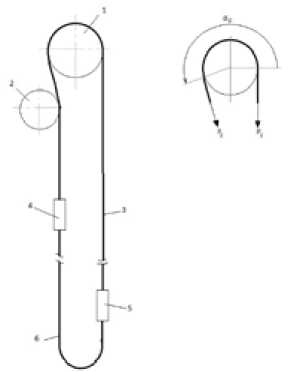
Fig. 1. T he gener al v iew of a hoisting machine with a fricti on pulley: 1 – g uide sheav ^ e; 2 – deflecting pulley; 3 – hoist (head) rope; 4, 5 – skips or cages; 6 – balance rope
Increasing hoistin ^ g cap acit y b^y raising t ^ h e frictio n c oeffic ient of the r ^ op e alo ng the liner of the pulley should be appro ached w ith som e cau ^ t ion, a s wit ^ h a high coef ^ fi cie nt of fric t ion it is possib le t o create situations wi^th broken ro^p es. Wit^h a^n i n cr eas e in t^he g ras pi ng a ^ ng le of th^e g uide sh ea^ve by a rope, the bending str es ses in the m also incre ase, wh ich le ads to decr eas ing ser vice l ife of the rope s and complex services during operation.
When considering t^he p os s ibility o f in^creasing the hoisting capacity of the winder with a friction pulley due to incre asing ten s ion o f th e b r anc^h e s, it i s gene ral l^y co ns idered to s pecify ins tallations with maximum and minim^ u m possibl e d e pths of a^p^pli catio n . T he max im^um possi^ble ho isting depth i s determined on the basis o f s afety mar^gin of t^he r op e [1, 2 ]:
σ z0 - zmi^n max = ,
Y0 zO zmin where σ – ultimate streng th of a rope, M Pa; Z0 – necessary static safety margin of a rope (ratio of . ......
tensile strength of the ro^pe to m aximu m s tatic tens ion in the c alculat ed c r oss secti on) , based on saf^e ty requirements; Zmin – m in imum al low a^ble saf^ety ma^rgin; γ0 – fi ct itio us rope d e nsi^ty, M Pa/m .
The verification of the cond iti on of p ermissi^ble pressure o f the r^o pes on t^he li ner of t^he guide sheave is performed acco rding to form^ula [1]:
S 1 + S 2 n ⋅ d r ⋅ D ^ s
≤ [S] ,
where S 1 and S 2 – static tension s of br anches of t^he ropes re spectiv^ely at th e p oi nts of ent ering and slacking directly at the g uide or b ea m shea^v^e; D s – dia^me ter of guide s^heave; d r – d^iame ter of the rope ; n - number of ropes.
The analysis of form^ula s (3) a nd (^4) allow s c oncl^uding that the m aximum hoi sting heig ht can be limited only by strength fa cto rs of the r op e. So , the sta^ndard s o f speci fic pre ssu re can b e fol lowe d by making a pulley of re qu i red d iam e t er. A t t hat, th e c ond iti on of n o n - s li^p o f th e r o pe s is ens u^re d by reducing maximum value of the co effi cient of static tens ions wi th in cr easing of dep th. At present, the maximum possib le theoret i c a l de p th o f a sc end i n g i s 2000 m f^o r mu lt i- rop e hoi s ts w ith clo s ed ropes [1].
A minimum allowa^b l e hoisting he i gh ^ t fo r a m^ ul ^ ti -rop e h^o ist is su^ch a h ois t ing h^eight w ^ h^en, i n the case of maximum use of the rope lead capacity, the. actual and allowable values of the static tensron coefficients become equal . I f t h is v al^u e i s ex^ceed e d , th e r^ope w il l begin to slip o n th e b lo ck [2 ]. In practice, for multi-rope in st a^llat io n s of sma^l l d ep th s, a m et^hod o f a^rti fic ia lly inc reas i ng we ig h^t of skips or ropes is used to e nsur e n on - sl ip o f the ro pe , how^ eve r^, t^h is red^uc es effic ie nc y o f h^oi sti n^g. O n the one hand, increasi ng we igh^t of sk ip s inc r eas e s th e sco^pe o f ap^p lication o f multi-rop e h oist ing at depth less than 600 m , on the o th er ha nd, it le ad s to an unr ea sona^bl e significan^t in crease in t^he material consumption of the entire machine and, as a result, increase of engine power and electric power consumption.
The next safety s ol ^ utio^n for th e slip resi stanc e co nd iti on is to incr ease sta ^ tic ten si o n of th e ro^pe s. In general, the safety facto r is determ ined by th e formula:
S 2 ⋅ (e fα - 1)
S 1 - S 2
At that, the static safety factor for slip resistance of the ropes must satisfy the condition:
σst =
Sst2 ⋅(efα-1)
S st1 - S st2
> 1,75.
where Sst2, Sst1 – respectively the static tension of the slacking and entering branches, defined by the formula:
Sst = (m1 + m 2) ⋅ g + (p ⋅ n ⋅ H + mw ) ⋅ g ,
whe re m1 – skip mass; m2 – mass of lifted load; g – gravitational acceleration; p – specific weight of the head (hoist) rope; n – a n^umber of h^ead rop es; H – heig ht of the hangi ng li ne; m w – mass of weights.
The dy namic saf^ety fac tor fo^r s l i^p res ist an ce of th e ro^pes o n t^he pu ll e^y m^ust s a^tis f^y th e condition:
fa
σ = S d2 ⋅ ( e - 1 ) > 1 .25 .
( 8)
d S d1 - S d 2
Dynamic tension of t^he ropes u s ed for enterin g a^nd sl ac king bran ch es a^re dete r^mi ned resp ect i vely by the formulas:
(9^)
(1 0^)
S d1 = S ^ st1 + m 3 ⋅ a ,
S^d2 = S^st2 -m^4 ⋅a, whe re m 3 – total mas s of th e l o ad of the ent e ring b r anch; m 4 – t otal m ass of the load of the slacki ng branch; а - acceleration (deceleration).
Th e a^na^lysi s o f f^ormul a s (^5- 10^) s^h^ o^ws tha^t th e b asi c value fo r d^etermi ni ng safet y fac tor is st atic tension of t^he r^opes. T^o cr^e ate a ddi t ion al e ffort, i^t is prop osed to insta^ll a tensio^ning de vice that creates tension in branches of t^he r ope and , th^us, ma kes it possib le to re fu se weighted ski^ps. The f^ormula for '' , , determining static tension of the ropes will take the form:
Ssf = ( m 1 + m2) ■ g + (p - n ■ H + m w ) - g + Д S + mt a , (11)
where AS - additional tens ion created by tlie tensioning device, m, - reduced m;iss of the tensioning device.
... .. ,
The idea of tensionin^g de^vi ces in hois ts with a friction pu lley was first ex^pressed by Pr^of. A.E . Trop . The w^ ork [^6 ] co^nt ain ed a t^heo reti cal r at ion al e o f t^he l oad c apa cit y d^e pendin^g on th e l iftin^g hei g ht, b a sed on th e s t atic h^o istin^g (e xcluding d^y na m ic loads^), to d eter mine the weight of the tension in^g device. The expediency of tens i o nin^g d ev ic es in i n cli n ed deep -p it ho is ts is i n di c a^te d i n [ 7].
A multi-rope hoist w ith a ten s io ning d e^v ic e has a n^u m be r of ad^van^t age s in c om pa ri s on to ho ist s w ith w^eighte d skip s. T h e mode of b r ea kin g the li ft in^g load is th e mos t da^n^ge ro^u s du^r ing t^he de sc ent- a scent process. The mass of the lifted (oad is calculated b>y the formula:
m = m ^ ∑ ⋅ [ (g + a) ⋅ (1 - e - fα ) - 2a ⋅ σ ] , (12^)
(g +. ). ( ,- 1 + e -a)
where mΣ – total mass o f e n^te ri ng /^slac^k ing b r an c^he s, eq^u al i n s ta^tica lly ba^la^nce d ho ist s ; σ – dyn am ic
..
sa fety c oeffi cient; α – ang le of the p ul ley c i rcum fere nce; f – fr iction coeffi cie nt.
When a skip is weighte d by a certai n am ount Δ m Σ , th e mass of the lifted load (m 2w) is in creased by Am 2 :
m 2w = m 2 + m 2 =
= m ^ ∑ ⋅ [(g + a) ⋅ (1 - e - fα) - 2 a ⋅ σ] + Δm ^ ∑ ⋅ [(g + a) ⋅ (1 - e - fα) - 2 a ⋅ σ . (13)
(g + a) ⋅ (σ - 1 + e - fα) (g + a) ⋅ (σ - 1 + e - fα)
Thus, from the analysi s of equ atio n (13) it fo llo^ws that the incre me nt of the load c apa city is direct^ly proportional to the weighting and i nve rsely proportion a^l to d eceleratio n. As dece lera^tio n inc reases, the fraction numerator decre ases, a nd the d^enom in at^o r in^crea s es, t^h e re fo re, th e fra cti o n value an^d th^e increment value of the lo ad ca^pac ity de c r eas e.
For a hoist with a te ns i on in g d ev ic e , th e tens ion o f enteri ng S 1 and sl a ck ing S 2 b ra^nche s is increased by ΔS due to t h e forc e g en e r ated by the t ension e r, w^hic h, in t e rm s o f incr eme n^t o f pay load
Δm 2, will be:
„ z d S - (1- e - a)
(14^)
Δm =
-
2 (g + a) - ( a -1 + e-fa)
The analysis of ex^pressio n (14^) sh^ow^ ed tha^t durin^g dece ler ati on grow th, the lifting ca^pacity o f the hoist decreases less than i n ho ists w it^h weigh^t ed sk ips, and th e use of ten s io n ing de^vic es is mo r^e effective than weighting of ski^p s. In add itio^n, hoists wi^th a tensi oning d evice are m ore effi cie nt in ter ms of hoisting dynamics. The use of tensioning devices allows operating hoists at smaller depths as well.
According to equation (13), the increment of load capacity is directly prop ortional to the increment of the mass of the branches and inv^ersely to d eceler atio n and also d epe nds o n the coef^fic ient of fr iction of the ropes along the liner o f t^he g uide sheav e and angle of g ras ping of the gui de sh eave . The depe nde^nce on the hoist deceleration , the fr ictio n coe ffic ient and g rasping angle can b e e^xpressed by a co nstant coefficient A – load co efficien^t when the hois t is lo aded by inertial loads . In th is case, the load c apaci^ty of the hoist, expressed by mean s o f the m ass of the ro^pes, is des cribed b y the eq^uat ion:
m2 = A ■ p ■ n ■ H , (15)
where p – specific weigh^t o f h ead (hoi st) rope; n – a num^ ber of head r^op es ; H – heigh^t of the ro^ pe hanging.
There is a certain heig ht o f the rope han^gin^g where the t ensile stre sses in the rope s reac h maximum permissible values, and the lo ad c apacity o f th e hoist reac^hes the hi ghest v a lue. W hen r ed^ucing th^e hanging height, the load capacity decreases, and the tension of the branches and the tension in the ropes also decrease, i.e. the rope s a re unde rloa d ed a^nd h ave a n exc essive ma^r^gin of safe ty^. To e n sure the greatest load capacity, the missing te nsion of t^he rop e s can be compe^nsa^ted f^o r by l o adi ng th e bra^nc hes with additional forces created by th e tensionin^g de vice, Fig . 2. If the ad ditio nal ten sion of the branches is expressed by means of t^he ma ss of the ro^p e s, th en t^he in cr^em ent of t^he lo ad ca^p acity w i ll b e:
^ m2 = B ■ p ■ n . X , (16)
where B – load factor when loading th e branches without inertia forces generated by the tensioning device; X – height of part o f th e ropes compe nsated by additi onal forces gen erated by the tens ioning device. In this case, the total loa d capacity m 2t of th e h^oist w ith te nsioning devic e is as fo llows:
m2t = m2 + z d m2 = (A ■ H + B - X) - p ■ n . (17)
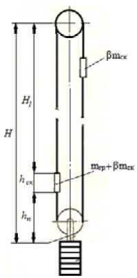
Fig. 2. The diagram of a statically balanced lifting system with a friction pulley and a tensioning device
Neglecting the inertia of the tension pulleys, the value of the coefficie^nts of proportionality A and B is determined by the foUowing assumptions:
-
- the hoist is statically balanced;
-
– the crite rion o f safety of work o f h ^ oist s w ith f ^ rictio n p ^ ulleys is the va lue o f dy namic sa fety coeffici ent, wh ic ^ h in all cases is tak^en not less tha^n 1 .25 ;
-
– the m os t dan ^ gerous m ode of ope ra ^ ti on o f the ho ist – de ce le r atio n at d e scen ding o f loa d;
-
– d ^ ynamic safety factor is determ ined by the formu la (8).
For a two-s kip ho is t with a t ensio n devi ce, th e to tal ten sion of th e sla cki ng (de scen^di ng) branc ^ h will be:
S 2 = (m 2t • (1 + в)-k i • m 2t + p • n •H) • g + + (m2t • (1 + в) + p • n • H) • a + p • n • X • g
w^here β – tare coe fficie nt; k ^ 1 – c o effic ient o f res ist anc e to t^he m ovem en^t of th e de s cen ding branch; g – gr avit ation al accelerat ion; a – dece lera ^ tion of the h^ois t during desc end^ ing of loa d.
Th e to^ tal tension of t^he en^ter ing (a sce^ndi ng) branc^h will be:
S 1 = ( β ⋅ m 2t + k 2 ⋅ m 2t ) + p ⋅ n ⋅ H + p ⋅ n ⋅ X) ⋅ g - ( β ⋅ m 2t + p ⋅ n ⋅ H) ⋅ a , (19)
w ^ here k ^ 2 – coefficien ^ t of res ista ^ nce to the m ^ ov eme nt of th e ascending bran ch .
Su ^ m it up s o far, w ^ e o ^ b tai n the form ^ ula s fo r calculati n^g c o ef^ficients A an d B :
(g + a) • (1 - e - fa ) - 2 • a • ст
(g - k ⋅ g + a) ⋅ σ - (g - k 1 + a) ⋅ (1 - e - fα ) - β ⋅ [(g + a) ⋅ (1 - e - fα ) - 2a σ ] , ( )
B =
g ⋅ (1 - e - fα )
( g - k ⋅ g + a) ⋅ σ - ( g - k 1 + a) ⋅ ( 1 - e - fα ) - β ⋅ [(g + a) ⋅ (1 - e - fα ) - 2a σ ] ,
( ^ 21)
where k – to^tal c oefficient of resistanc e to movem^ent of the branc hes.
When studying the i nfl^u^en^ce of th e r^ope s tre ng th to the lo ad capac ity of the hoi st, it is nec essary to take into account that A a^nd B co e ffic ients depen d o n d ec ele r atio n valu^ es of t^he ho ist, on t^he ta re
- 149 - and safety factors for slip r^es is tance , as well as on the friction co efficient an d t^he g rasping an^gle, in .
proportion to which the loa d c a^pacit y ch anges, c on seq^ue n^tl^y, th e g reates t lo a d cap ac ity is ac h iev ed depending on their value at different heights of the hanging line of the ropes.
The static safety margin of the ropes Z is equa 1 to:
z = STn , S max
(2 2)
where n – a numb er o f rope s; S b ^ r – tot al bre ak in g st^r en^gt^h of all wire s o f t^he rope , H ; S ^ max – maximum static load of load branch, H.
Maximum stoitic load capacity is delermined Id y the formula:
S max = (m ^ 2 t ⋅ ( β + 1) + p ⋅ n ⋅ (H + X ) ^ ) ⋅ g .
The height of the part of the ropes X, compens,ted by add t o n a forees of tensioning devices, is defi ne d as diff^eren ce b etwee n pe rmi ssib le li ftin g heig h^t Н max with the gr eat est payload under the condition of slip resistance and actual lifting height H:
X = Hmax - H.(24)
After app rop riate transform ati o ns, the formul a for de^term ining the permissible lifting height of a multi-rope hoist with a tension device will take the form:
,
Hm fX =-----------Lbr-----------,(25)
max К-(1 + p)• (A-H + B • X) ’'
w^here Lbr – cri^tical br^eak ing length o f the ro^pe, defined by the form^ula:
Lb = Pbq-(26)
The maximum load at permissible height of the rope is determined by tl)e exp)ressions:
-
– with a constant safe ty mar^g in o f the rop es: p
mA=A.p.n .HA,(27,
-
– with a variable safety m arg in of the rop es:
m'A = A. p-n. tf'A.
I ZI^SS i. . r^, . .,..,.
The analysis of formu la s (^2 0) an^d (2 1) s ho wed tha^t A < B . This fac t m^ e ans th a^t th e termina^l lo ad gr^ows slower i n case of t^h^e increm^ent in th e heig ht o f rope hangin g th an w he n com p e n sa^ti n^g for the m.ssing tod of th., branches with forces generated by a )e n s. n „g device. Consqu.ndy, in in stal la^tions with a t e nsio n e r, t^h^e tens io^n in the ro^p es w il l reac h the m ax i mu^m p e rm issibl e v al^ue s a^t compensatin^g par t of rop e han ging w ith sho rte^r l eng th t^han per m issib le he igh^t Н^max.
eAnalyzing formula (2 -4), we dete rm ined that under various operatingf conrfitions for hoists without ten sion in g devi ces w^he re X = 0 , the actu al hoist ing h eig ht H te^ n^ds to th e v^alu e of the p erm iss ible hoist i ng h ei g ht Нm a^x. W hile fo r hois ts with te nsio^ning d e^vic es w^h ere the depth of ascending tends to z ero, the v al^ue of X tend s t o Нmax . T he re fore, i^t is p ossi^ble to ass ume t^he c oi ncidence of the load — 150 - capacity graphs under the condition of rope strength for the hoists without a tension device and with a tension device.
The load capacity as well as the permissible rope hanging height are determined uniquely for each hoist with specified parameters and will differ when they change. To clarify restrictions on the load capacity under the condition of permissible specific pressures on the liner of the guide sheave, we consider a hoist where the ropes are hung with the total weight of both branches creating pressure on the liner equal to the permis sibl e one.
The total tension of bo^th b ra nche s of the in stalla^tion S Σ is determi ned by th e formula :
(^29)
(^30)
S E= (m 2 ■ (2 - в + 1) + 2 - p - n - H) - g .
The specific pressur^e o n t^h e l iner of t^he pu l ley w ill b e:
: ,
Ds dr n where Ds – the diameter o f guide s^heave; dr – th e d iamet er o f th e rope.
The ratio of the diame ter of th e rope to th e d^iamete r of the gu id^e sh eave ( δ ) is co ntro lled b^y the safety rules and determined by the formula:
5 = D s . d r
(31 )
(32^)
The ratio of the weig ht o f a meter of rop e to the s quare of it s d^iame ter ( λ ) :
-
3 • у
- dr2 .
The final equation of the load capacity of the hoist under the conditions of permissible pressure on the liner will take the f^orm:
m 2 =

- H I- p ■ n
1 + 2 -в
In the final equatio ns o f l o a d c ap acit^y u nd e r the c o n d itio n s, su^c^h a s: s lip r e sis ta^nc e o f th e ro^p es , their strength and permis s i^bl e s pe c i fic pre s su^r es on th e l in^e r of th^e p u ll e^y, th e lo a d c apac i^ty o f t he installations with a friction pul le y i s repre s en^ted as a de pen^ de nt v^alu^e on m ass o f a m^ e te r of the bran c h of the ropes. Equating tiie mass of a meter of ropes to one (p • n = 1), it is possible to make some general graphs covering hoists by loiid capacity a nd lifting heiight from zero to the: maximum piossilde values with constantly specified parameters, such as: safety factor for slip resistance, coefficient of tare, coefficient of cabl e f^ri ct ion on th e lin er of the p ull ey^, an^gl e of g ra s p o f th e g u id^e s he ave by r^op es , resistance to movemen^t o f br anch es, d^ec el er a^tion o f sk ips , s tr e^ngth of t^h^e ro p e s a^nd the lin er .
If we chart the load ca^pacity, it is adv i sable to sh ow t he followin^g e xample. To co nstru^ct the diagram, we plot on abscissa – t^he lifti ng he ig h^t, on o rd i na^te – the loa d c apacit^y of h oist.
..
We consider a hoist wit^h a frict io n pul le^y and a te n si o n ing d^evice , eq^ui^pped with t^he rop es of a similar design, having a te m^por al te n sile s t^reng th σ^o = 16 0 0 MPa , a b re ak ing l ength of the ro pe L br = 18400 m and coeffi c ien^t λ = 5 6.7 ∙ 1 0 3 k ^ g /c m2 , li f^tin g s ki^p s wit^h tare c o effi c ient s β = 0.5 .
The following values were taken in calculations: deceleration during the descent of the load а = 1.5 m/sec2 ; dynamic safety factor for slip resistance σ d = 1.25 ; movement resistance coefficients k = 0.15 and k1 = 0.09 ; coefficient of friction of the ropes on liner µ = 0.25 ; angle of grasp of guide sheave α = 1800 ; specific permissible pressure on liner of the pulley γ 1 = 2.5 MPa . According to the adopted main parameters of the hoist, the values of proportionality of the load capacity coefficients were calculated by the formulas (20), (21): A = 0.237 and B = 0.697 .
The construction of load capacity diagrams (Fig. 3) is performed in the following sequence:
-
1. Take arbitrarily the values of coefficient A :
-
– the values of permissible heights of rope hanging with a constant safety margin are found by formula(25);. . .....................
-
– the maximum load capacities corresponding to the allowable heights are calculated by formulas (27, 28).
According to th e calculated values (formula (27)) we construct graph 1 with safety margin of the rope K = 7 an^d g raph 2 with K = 4. 5 . According to form^ula (28) we bu ild gr aph 3 for a v ariable sa^fety factor.
-
2 . The value of the height of the ropes – H is given arbitrarily by formula (33), we build load capacity graph 4 under the conditions of perm issible specific p^res sures on the liner of the pulley: γ = 2.5 MP ^ a , and graph 5 with γ = 5.0 MPa .
-
3. T he k^nown value of coefficient of proportio nal ity: A = 0.237 a^nd arbitra^ry v^ al^ues of rope hang ing heigh^ t – H are given by for^mula (15). W^ e build gra^ph 6 for the lo ad c ap acity of the hoist without a tension device.
-
4. Th e w^eightless ro^ pes with the kno^wn v^alues L br , k, β and В are given. W^ e determin^ e a co^nditional per^miss ible height and , ac cording t o f^orm^ ula (17 ), we calculate the max im^um l oad cap acity of the installation under the condition of additional tension of the branches created by a tensioning device. Th e giv^en position of the w^ eightlessness of t^he ro^pes e xpl ains the positio n of a p oint corres^ponding to the gr^eatest load cap acity on or^dinat e of the insta lla^tion with a tensi oni ng device. It is the point “a” . Th e second poi nt “c” is defined a s com mon for hoist s with tension ing d evices and witho^ut them. It is
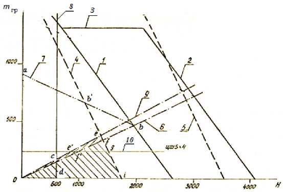
Fig. 3. Load capacity diagram of hoist at a = 1.5 m/sec2
expressed by the intersection of graphs 6, 1 and 2. Connecting points a and b, we find graph 7 reflecting the load capacity under the condition of slip resistance of the ropes for hoists with tensioning devices.
Chart 8 is a line characterizing restriction of the use of multi-rope hoists without weighted skips at the depth less than 600 m. To analyze the diagrams, it is advisable to construct additionally load capacity graph 9 with weighted skips: β = 1.0 and A = 0.268. The graph also reflects load capacity of installations with counterweights. It should be emphasized that in this case, the load capacity determined from the diagram corresponds to value m2 /2 .
The analysis of the obtained diagrams allows the following conclusions:
-
1. Operating hoists with friction pulleys are described by the area of the diagram, the perimeter of the area is determined by the lines drawn by means of “cfid” points, it is about 8 % of the entire area of the diagram (Fig. 3). The use of weighted skips: β = 1.0 expands the scope of application of hoists with friction pulleys slightly. According to the value described by the area of diagrams, the perimeter of which is determined by the lines drawn through “0еgi” points, and the scope of application increases at decelerations 1.5 m/sec2 by 9 %. For example, the machine with 5х4 flat-faced pulley (a horizontal line 10) is indicated. The calculations show that when deceleration is reduced to 0.5 m/sec2 with weighted skips, the scope of application for hoists with friction pulleys does not exceed 30-35 % of the total area of possible application. Besides, round-strand ropes are exposed to a significant stretching up to 0.5 %, which makes it difficult, especially in case of a double skip ascent, to stop lifting skips at given loading and unloading points and also requires more attention to the leveling of the loads between the ropes.
-
2. The application of tensioning devices in hoists allows expanding the scope of application of hoists with friction pulleys by 2 ^ 3 times, especially at depths 600 ^ 800 m or less. It appears from the diagram that the parameters of using of hoisting machines with friction pulleys and tensioning devices are determined by graph 4 (load capacity under the condition of permissible specific pressures on the liner of the guide sheave) and graph 7 (under the strength condition of the ropes when applying tensioning devices). The diagram area is described by “ ab/efgi0” points.
-
3. Further expansion of the hoists application scope with friction pulleys covering the entire area of the diagram at simultaneous growth of the load capacity can be achieved by using lining materials with a permissible specific pressure up to 5.0 MPa .
It should be noted that the idea of using tensioning devices in hoists with a friction pulley has not been fully implemented until now. There are some real projects for the application of such devices. We consider, for example, a pulley as a tensioning station of a cargo drive which is located on terminal ropes with a load hung to it. Depending on the load capacity and height, the weighting mass of the tension station can reach tens or even hundreds of tons, the volume of tension load can be made of cast iron or steel 15 ^ 20 m 3 , concrete or reinforced concrete - 50 ^ 60 m3 and more. It can create additional difficulties in placing the load in the shaft. In this case, the reduction of material consumption can be achieved by using hydraulic tensioning devices. Figure 4 presents a general view of a hoist with a hydraulic drive of a tensioning device and a schematic diagram of a tensioning device protected by copyright certificate No. I02034I (USSR) [8].
The presented design of the tensioning device allows choosing elongation of ropes, resulting from residual deformation automatically by starting a hydraulic drive at the calculated force. As the ropes are drawn and the sloping part of wedges is used, an additional removable liner is installed, during the installation period the tensioning device is fixed by tightening bolts.
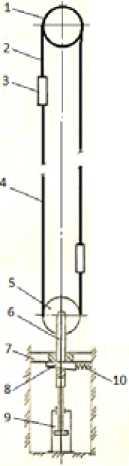
Fig . 4. The ge neral v iew of hoist with a te ^ nsioning devic e and a hy ^ draul ic drive: 1 – gui de sheav e; 2 – head (ho ist) rop e; 3 – sk ip; 4 – tail (b al ancin g) rope; 5 – ten sioner p ^ ul ley ; 6 – traction tensione r; 7 – frame; 8 – wedge; 9 – h ^ y-dr au lic cylinder; 10 – spring
Conclusions
The use o f tensioni ng devic es allows ex^pand^ ing the sc ope of applica^ tio^n of ho ists w ith frictio n pulley s at sm all er depths w ith no artifi cia l weigh ing of skips, increasing material consu mp tion of the in stalla^tion a s a w^ hole, further incremen^ting pow^er of hoist engin^e and , as a con seq^uence, maintai ning gener al hoisting effi ciency. The use of tensioning devices allows approaching the design of skips from the view of strength using lightweight materials.
The work of tensioning devices is more effective when the depth of the shaft does not exceed 800 m.
The application of tensioning devices improves the design of skips from the view of strength with the use of lightweight materials, generally providing a significant reduction in the material intensity of the installation.
References Increasing scope of application of multi-rope hoists with friction pulleys in small-depth mine shafts
- Bezhok V.R., Dvornikov V.I., Manetz I.G., Pristrom V.A. Mine hoisting, Donetsk, South-East, 2007.
- Pesvianidze A.V. Calculation of mine hoisting facilities. Moscow, Nedra, 1992.
- Dimashko A.D., Gershnikov I.Ya., Krevnevich A.A. Electric mine winches and hoisting machines. Moscow, Nedra, 1972.
- Nesterov P.P., Shabanov-Kushnarenko Yu.P., Melentyev Yu.I. Expansion of the scope of application of multi-rope hoists due to installation of opposing pulleys. Izv. Universities. Mountain Journal, 1965, 4.
- Ivanov I.D. Multi-rope hoisting machines and features of their technical operation. Izv. Universities. Mountain Journal, 1971, 8.
- Kabanov V.A., Factorovich A.M. Ways of expanding the scope of application of multi-rope mine hoists with friction pulleys. Izv. VUZov. Mining Journal, 1960, 7.
- Bykov V.L. Multi-rope hoisting installations with rope-guide pulleys for deep quarries. Izv. Universities. Mining Journal, 1968, 4.
- A.S. I02034I (USSR). Hoist installation / Production Association "Apatite"; Auth. invented S.S. Naumov. Appl. 07.06.81 No. 33I2I83 / 29-II; Publ. in BI, 1983, No. 20; MKI3 B 66 B 7/10.
- Naidenko I.S., Bely V.D. Mine multi-rope hoist. Moscow, Nedra, 1979.
- Naumov S.S. Development of schemes and devices for the expansion of the scope of multi-rope hoists. Thesis for the degree of candidate of technical sciences. Leningrad, Mining Institute, 1987.
- Kragelsky I.V., Vinogradova I.E. Friction coefficients: a reference book. Moscow, Mashgiz, 1955. 188 p.
