Increasing the efficiency of bladeless fans by applying longitudinal cylindrical grooves on the diffuser walls

Author: Bryzgunov P.A., Grigorov V.A., Grishin L.E.
Journal: Siberian Aerospace Journal @vestnik-sibsau-en
Section: Aviation and spacecraft engineering
Article in issue: 3 vol.26, 2025.
Free access
The paper investigates the possibility of increasing the efficiency of bladeless fans by applying longitudinal cylindrical grooves to the inner walls of the diffuser. Bladeless fans, which are jet pumptype superchargers, show promise as propulsion systems for small aircraft with electric and gas turbine engines. The key parameter determining their efficiency is the flow entrainment ratio, which depends on the geometry and aerodynamic quality of the air passage. In this study, we perform numerical simulations to assess how the geometric parameters of the cylindrical grooves affect the fan’s aerodynamic performance. We consider the diameters of the arcs forming the grooves (3, 6, and 9 mm) and the angular step of their placement (2°, 4°, and 6°) as variable parameters. We carry out aerodynamic calculations in a threedimensional periodic setup using the ANSYS CFX software package with the k-ω SST turbulence model. Our results show that, at a fixed total pressure at the outlet of the annular gap, the primary airflow rate remains constant across all configurations. The highest efficiency occurs with a groove diameter of 6 mm and an angular pitch of 2°: in this case, the secondary airflow increases by 2 %, and thrust rises by 4 % compared to the base model without grooves. We analyze turbulent kinetic energy fields and visualize vortex structures, revealing that this configuration produces the lowest turbulence intensity and smallest vortex scales in the nearwall region, which enhances momentum transfer from the jet to the surrounding air. Grooves with a smaller diameter (3 mm) have almost no effect on performance, while larger grooves (9 mm) increase flow turbulence and reduce efficiency. Engineers can use these findings to develop highly efficient propulsion systems for unmanned aerial vehicles.
Bladeless fan, Coanda effect, air injection, longitudinal cylindrical grooves, turbulent kinetic energy, aerodynamic drag
Short address: https://sciup.org/148332089
IDR: 148332089 | UDC: 533.697.5 | DOI: 10.31772/2712-8970-2025-26-3-368-378
Text of the scientific article Increasing the efficiency of bladeless fans by applying longitudinal cylindrical grooves on the diffuser walls
Bladeless fans, now widely used in ventilation and air conditioning, are jet pump-type blowers and operate similarly to injectors. The term "bladeless" refers only to the fan's appearance, as the impeller is mounted in a special casing. Figure 1 shows a typical bladeless fan design, including a supply duct, an annular interior space ending in an annular slot, and a diffuser. When this type of fan operates, air 1 is forced by the high-speed impeller and directed into the supply duct 1 . It is then uniformly distributed within the interior space 2 across the area of the annular slot 3 , where it is accelerated due to the significant narrowing of the slot. The high-velocity airflow is directed by the annular slot 3 along the walls of the diffuser. By selecting the appropriate geometric parameters, the air stream does not detach from the diffuser walls but adheres to them due to the Coanda effect. The momentum of the highspeed jet is partially transferred to the undisturbed flow, creating a vacuum in the throat of diffuser 4 , which attracts additional secondary air, which is directed, along with the primary air, to the outlet of diffuser 5 . This allows for a significant increase in air flow rate, up to 20–25 times [1].
Obviously, due to the law of conservation of momentum, the use of bladeless fans does not allow for greater energy efficiency compared to traditional vane blowers; however, their undoubted advantage is a smoother air flow at the outlet, which has significantly less turbulence, which is achieved by accelerating the primary air in a narrow annular gap.
This advantage has driven significant interest in bladeless fans over the past decade as promising propulsion systems for small aircraft, both electric and gas turbine powered. Using gas turbine propul- sion essentially creates a turbofan engine, where the turbine drives the supercharger impeller. An example of such a project is the aircraft developed by the US startup Jetoptera [2].
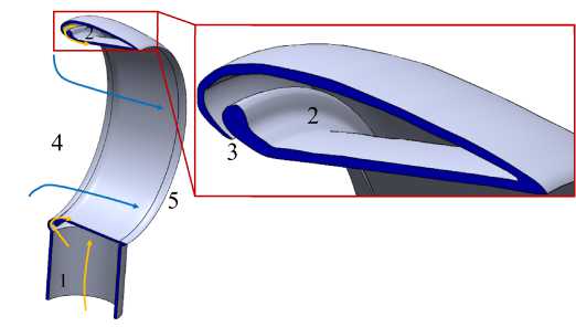
Рис. 1. Устройство безлопастного вентилятора:
1 – подводящий канал; 2 – внутреннее пространство; 3 – кольцевая щель;
4 – горловина диффузора; 5 – выход диффузора
Fig. 1. Bladeless fan structure:
1 – supply channel; 2 – technology space; 3 – annular gap; 4 – diffuser throat; 5 – outlet diffuser
For small multicopter-type aircraft, the use of bladeless fans also improves the aircraft's safety, as these propellers have no external rotating parts, making them resistant to small and large rocks, birds, and anti-drone nets. Examples of research papers on this topic include articles [3; 4], which are devoted to the development and creation of prototypes of unmanned aerial vehicles (UAVs) with bladeless propellers based on electric motors and their automatic control systems. Also of interest are patents [5; 6], which describe the concepts and design features of such UAVs.
One of the key characteristics of a bladeless fan is the flow rate multiplication factor U , defined as the ratio of the airflow rate at the diffuser outlet to the primary airflow rate discharged through the annular gap. For a fixed primary airflow rate and annular gap inlet pressure, this parameter largely determines the generated thrust, since the velocity at the diffuser exit also depends on the airflow rate at the outlet. According to the fundamental injection equation, the U coefficient can be found as:
U =
ф
1+Z,
where Φ – the ratio of the cross-sectional area of the annular gap to the area of the diffuser throat; ζ – drag coefficient of the annular gap and diffuser.
Thus, the theoretical value of U depends only on the area ratio Φ and the hydraulic performance of the air duct. A significant number of studies have been devoted to investigating the influence of the geometric parameters of a bladeless fan on its efficiency, examining the influence of both the fan shape and the diffuser opening angle [7], as well as the area of the annular gap, throat, and diffuser outlet section [8–14]. Based on the analysis of these studies, a detailed review of which is presented in article [14], it was established that, among the above-mentioned parameters, the area ratio Φ has the greatest influence, and, in general, this influence, in the absence of jet separation or deflection, corresponds to theoretical formula (1). For a fixed throat diameter and primary air flow rate, a decrease in the annular gap flow area leads to an increase in U , but this requires an increase in inlet pressure, which leads to increased energy costs.
However, the diffuser's ζ coefficient, in addition to the opening angle, can also be affected by the surface treatment used to suppress vortex formation. As air flows along the diffuser walls, a turbulent boundary layer typically forms. This vortex structure dissipates some of the jet's initial kinetic energy, resulting in less energy being transferred to the undisturbed air and, consequently, reduced injection.
To improve the aerodynamic performance of surfaces, various modifications are used, such as the installation of dimples [15], transverse grooves [16], and longitudinal ribs [17]. The installation of dimples and transverse grooves allows for a drag reduction of 5–10 % due to the formation of vortices in them, which creates a vacuum that helps minimize flow separation. The installation of longitudinal ribs on the surface allows for a reduction in the scale and energy of the resulting vortex structures, thereby reducing aerodynamic drag by approximately 5–6 %. It is assumed that the application of grooves will reduce flow turbulence by a similar mechanism without reducing the cross-sectional area of the diffuser.
The objective of this study is to investigate the aerodynamic characteristics of a bladeless fan depending on the geometric parameters of longitudinal cylindrical grooves applied to the walls of the diffuser wall in the direction of flow.
Object and methodology of the study
The bladeless fan geometry described in patent [18] was chosen as the baseline, with a throat diameter D of 540 mm, a diffuser length L of 240 mm, and a diffuser opening angle of 14°. The baseline design was supplemented with cylindrical grooves with an arc diameter d , applied to the diffuser walls in the direction of the medium flow with an angular pitch of α (Fig. 2).
In this paper, we considered fan configurations with groove diameters of 3, 6, 9 mm at angular pitches of 2°, 4°, 6° in comparison with the base model without grooves.
To reduce computational effort due to the axisymmetric flow in the diffuser, the initial geometry was simplified, and numerical simulations were performed in a three-dimensional periodic formulation. Figure 3 shows an example of the computational mesh. The number of mesh elements was 3.5 million, including tetrahedral elements in the main flow zone and prismatic elements in the wall zone. The average y + values for the first wall cell were 1.8; the minimum was 0.1; and the maximum was 3.7. This ensured that y+ < 5, necessary for using the selected k-ω SST turbulence model [19], was met. ANSYS Meshing was used to generate the mesh.
After constructing the mesh model, the solver was configured using the ANSYS CFX package. Figure 4 shows a sketch of the computational model with the specified boundary conditions. An inlettype boundary condition (BC) for total pressure was specified at the primary air inlet, rotational periodicity was specified on the lateral surfaces of the computational domain, and pressure with an opening BC type was specified on the surfaces connected to the surrounding environment. The opening type was chosen because using this setting in ANSYS CFX reduces the computational error in the presence of reverse currents on both the suction and discharge sides of the fan. All other surfaces were specified as impermeable walls.
For all fan models, the same values of excess air pressure at the gap inlet were set: 20 kPa. The ambient excess pressure was assumed to be 0.
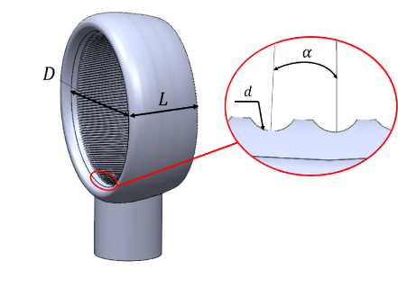
Рис. 2. Геометрия и ключевые размеры исследуемых моделей вентиляторов
Fig. 2. Geometry and key dimensions of the studied fan models
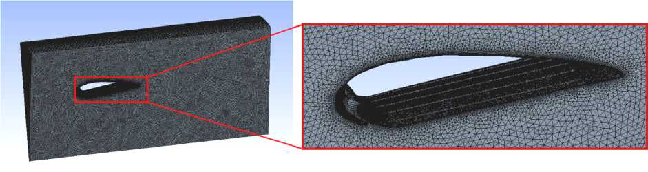
Рис. 3. Пример расчетной сетки
Fig. 3. Example of a computational grid
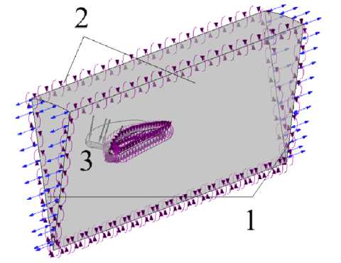
Рис. 4. Эскиз расчетной модели с обозначением граничных условий:
1 – ГУ окружающей среды; 2 – ГУ периодичности; 3 – ГУ входа первичного воздуха
Fig. 4. Sketch of the calculation model with boundary conditions:
1 – ambient GB; 2 – periodicity GB; 3 – primary air inlet GB
Research results
According to the results of the numerical simulation, at a fixed inlet pressure, all fan models provide the same primary air flow rate of 0.79 kg/s (from here on, the flow rate and thrust values are given in terms of the full fan circle).
Figure 5 shows the flow velocity profile at the diffuser outlet for the fan models considered. As can be seen from Figure 5, the most complete velocity profile corresponds to the configuration with a groove diameter of 6 mm and an angular pitch of 2°. This geometry provides the smallest crosssectional area with a velocity of less than 10, indicating better momentum transfer from the high-speed wall jet to the undisturbed air.
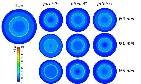
Рис. 5. Эпюры полей скорости в сечении модели, соответствующем выходу из диффузора
Fig. 5. Velocity field diagrams in the model section corresponding to the diffuser outlet
The 6 mm groove diameter and 2° pitch configuration also produce the highest flow rate (Fig. 6). As can be seen from Fig. 6, this is the only geometry that provides an increase in efficiency over the base geometry with a 2 % increase in flow rate. A 2 % increase in flow rate at the diffuser outlet allows for a 4 % increase in thrust generated by the diffuser as a propeller without changing the primary air flow rate and pressure (Fig. 7). This increase in efficiency is small, but it is achieved without increasing the primary air flow rate and pressure at the inlet, unlike a reduction in slot thickness.
With groove diameters of 3 mm, efficiency remains virtually unchanged, slightly declining. This suggests that a 3 mm diameter is small, and adding grooves of this diameter reduces aerodynamic efficiency by 0.5–1 %. With a groove diameter of 6 mm, efficiency increases only with a minimum pitch of 2°; in this case, the groove geometry degenerates into ribs. With a larger groove diameter of 9 mm, efficiency decreases significantly, making their use unacceptable.
In order to determine the reasons for the different efficiency of grooves with different pitches and diameters, turbulent kinetic energy (TKE) fields were constructed on the surfaces of vortex structures formed during the flow (Fig. 8), as well as graphs of the dependence of the average TKE on the area of vortex structures on the groove diameter and the angular pitch between them (Fig. 9). As can be seen from Fig. 8, with a groove diameter of 3 mm, the TKE distribution is similar to that in the base case, while the average TKE also coincides with the base configuration. With a groove diameter of 3 mm and a pitch of 2°, the average TKE is lower by 7 %; however, Fig. 8 shows that for this fan model, the scale of vortex structures is larger, in particular, there is a significant vortex roll on the trailing edge. For grooves with a diameter of 6 mm, a slight decrease in the average thermal coefficient of performance (by 5 % and 10 %, respectively) is observed for pitches of 4° and 6°, but a slightly larger scale of vortex structures is visible compared to the baseline. For a groove diameter of 9 mm, larger vortex structures are observed at all pitch values compared to the baseline, with a thermal coefficient of performance 2.7 times larger. This suggests that larger groove diameters further turbulent the flow, thereby reducing fan efficiency.
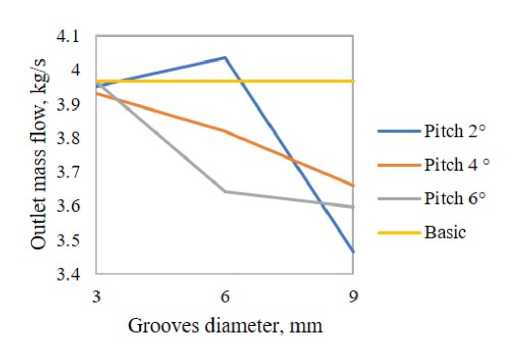
Рис. 6. Зависимость расхода воздуха на выходе из диффузора от диаметра канавок и углового шага их размещения
Fig. 6. Dependence of air flow at the diffuser outlet on the diameter of the grooves and the angular pitch of their placement
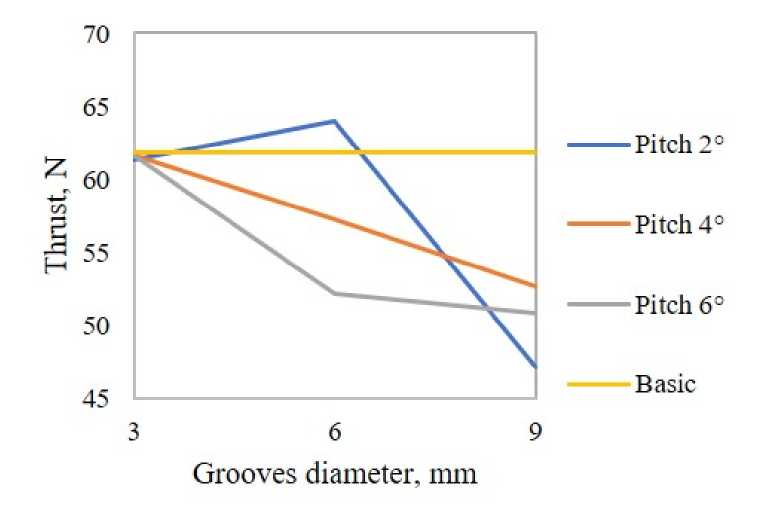
Рис. 7. Зависимость создаваемой вентилятором тяги от диаметра канавок и углового шага их размещения
Fig. 7. Dependence of the draft created by the fan on the diameter of the grooves and the angular pitch of their placement
The previously identified optimal configuration, with a groove diameter of 6 mm and a 2° pitch, has the lowest average thermal coefficient of performance among the configurations considered (15% lower than the baseline), as well as a small scale of vortex structures The decrease in the intensity of turbulence can be explained by the formation of small-scale, but sufficiently energetic, paired vortex bundles in the grooves, under the influence of which, due to the rarefaction they create, the flow is pressed against the wall, which reduces the intensity of the vortices at a distance from the wall. However, this hypothesis requires experimental confirmation.
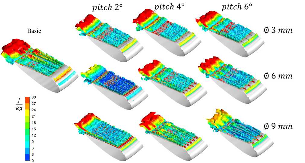
Рис. 8. Визуализация вихревых структур и распределения ТКЭ при течении воздуха в моделях вентиляторов
Fig. 8. Visualization of vortex structures and TKE distribution during air flow in fan models
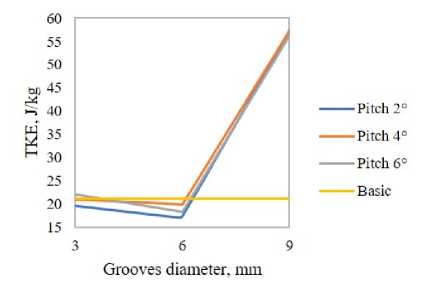
Рис. 9. Зависимость средней по площади поверхности вихревых структур ТКЭ от диаметра канавок и углового шага их размещения
Fig. 9. Dependence of the average surface area of the vortex structures of the TKE on the diameter of the grooves and the angular pitch of their placement
Conclusion
This study optimized the diameter and angular pitch of cylindrical grooves applied to the diffuser walls of a bladeless fan. It was found that the configuration with a 6 mm groove diameter and 2° pitch produced the highest flow rate. This configuration provided a slight increase in efficiency: a 2% increase in flow rate and a 4% increase in thrust compared to the base fan geometry. This increased efficiency is due to a reduction in the intensity and scale of vortex structures, which was not observed in the analysis of other configurations.
One of the potential areas of application of the research results is the creation of advanced propulsion systems for small aircraft using bladeless fans as propellers.
Acknowledgment. The work was conducted within the project “Development of technical solutions to improve the efficiency of aircraft gas turbine engines” with the support of a grant from the National Research University “MPEI” for the scientific research program “Priority 2030: Technologies of the Future” in 2024–2026.
