Increasing the specific impulse of an oxygen-hydrogen liquid rocket engine by in-creasing heat transfer in the combustion chamber

Author: Vasilevsky D.O.
Journal: Siberian Aerospace Journal @vestnik-sibsau-en
Section: Aviation and spacecraft engineering
Article in issue: 4 vol.23, 2022.
Free access
Liquid-propellant rocket engines (LPRE), operating according to a gas-free generator scheme, are used for the upper stages of launch vehicles and upper stages. In engines of this scheme, only cryogenic fuel is used, which provides a high engine STI. Also, a distinctive feature is the absence of a gas generator, the combustion generators of which feed the turbine of the main turbopump unit. In the gas-free LPRE scheme, the turbine is driven by gas-return hydrogen heated in the cooling loop. Therefore, the high parameters of the LRE, such as the pressure in the CC, the thrust of the engine and the specific thrust pulse depend on the effective heat removal from the firing wall of the combustion chamber and the intensification of heat ex-change in the cooling path. There is a number of solutions that allow to increase the amount of heat transferred to the refrigerant in the inter-shirt space. Therefore, the search for an optimal cooling scheme and promising design solutions for the intensification of heat transfer in the engine cooling path will allow us to determine the high param-eters of the LPRE. This article discusses the effect on the thermal state of the combustion chamber of the gas fins installed on the firing wall of the engine. Gas fins belong to the developed heat exchange surfaces and increase the area of the side surface of the combustion chamber. With the help of the developed mathematical model of the cooling chamber of a gas-free LRE, extremes in the intensification of heat exchange in the cooling path have been identified. The dependences of the specific thrust impulse of the engine on the pressure in the combustion chamber and the geometric dimensions of the engine are also obtained.
LPRE of the expaned cycle circuit, thermal protection of the engine body, mathematical model of LPRE, pneumatic-hydraulic circuit, heat and mass transfer of combustion products
Short address: https://sciup.org/148329660
IDR: 148329660 | UDC: 629.7.036.54 | DOI: 10.31772/2712-8970-2022-23-4-671-687
Text of the scientific article Increasing the specific impulse of an oxygen-hydrogen liquid rocket engine by in-creasing heat transfer in the combustion chamber
At present, one of the main tasks is the further exploration of outer space, flights and the exploration of the Moon, the implementation of the idea of using Sun energy. This requires the development of new space rocket systems and spacecrafts using highly efficient and reliable liquid-propellant rocket engines (LRE), which are subject to the following requirements:
-
– high specific thrust impulse;
-
- a large degree of nozzle expansion;
-
– high pressure in a combustion chamber;
-
- a great resource;
-
- the minimum cost;
-
- low boost pressure tanks;
-
- minimum overall dimensions.
It is possible to fulfill these requirements with the help of engines, which are created using new circuit and design solutions, which make it possible to significantly improve the characteristics and reliability of operation. The need to provide a given resource and the possibility of multiple use of engines poses difficult questions for their developers regarding the choice and design of pneumohydraulic systems of engines and the space block as a whole. The implementation of these measures allows to speak about the beginning of a qualitatively new stage in the development of space rocket engines.
The use of existing disposable launch vehicles and reusable transport spacecraft (RTSC) [1] satisfies only part of the requirements for the entire system of payload delivery vehicles. At least one more space system is needed (orbital transfer vehicle (OTV) or upper stage rocket (USR)), capable of delivering a payload from low earth orbit to its destination.
In particular, OTV and USR are designed to solve two main tasks:
-
– delivery to high Earth orbit and rapid return of manned and unmanned satellites and spacecraft;
-
– relatively slow transfer to geosynchronous (geostationary) orbit of large space structures assembled or deployed in low earth orbit.
In connection with the high material costs for launching spacecraft, it is urgent to consider the issue of the feasibility of reusable [2] OTV.
To implement the reusability, the best option is to use a generatorless liquid propellant rocket engine.
This type of scheme has the following advantages:
-
- simplicity of design;
-
– high energy characteristics;
-
- a large resource of work;
-
- high reliability due to the use of one firing unit as part of the engine;
-
- reducing the time of experimental development, fine-tuning and production;
-
– high cost-effectiveness due to the absence of losses in the air specific impulse (ASI) for internal cooling of the fire chamber wall.
At the moment, the developments of gas-free LREs existing in Russia and other countries show that the use of gas-free schemes is very promising for their use as rocket engines for OTV [3].
A distinctive feature of gasless LREs is that they operate exclusively on cryogenic fuel components (oxygen, hydrogen, methane) and have a high specific impulse. An important feature of cryogenic fuel components is their environmental friendliness and high energy and thermodynamic parameters.
In gasless engines, due to the high cooling abilities of the coolers used, intensive cooling of the LRE chamber is possible with a moderate thermal state (TS) of the structure. Due to the high specific gas constant of cryogenic fuel components and high heating of the coolant in the cooling path of the combustion chamber (CC), the operability of the gas (zRT complex), which then goes to the turbine drive, it is possible to significantly increase the adiabatic operation of the turbine of the turbopump unit (TPU).
Depending on the intended flight trajectory and the main technical requirements for the OTV, the use of a gas-free LRE scheme as part of the OTV makes it possible to de-orbit payloads due to the possibility of engine operation over a wide range of pressures and thrusts.
Forcing the parameters of the base engine of the prototype or increasing the efficiency of the engine, that is increasing the ASI and thrust, increasing the pressure in the CC in the gas-free LRE scheme is possible due to the maximum amount of heating of the coolant in the cooling path [3]. In contrast to the scheme with afterburning of oxidizing generator gas and reducing generator gas, where the increase in pressure in the chamber is realized due to an increase in pressure in the gas generator (GG), which complicates the design of the GG and imposes requirements for the implementation of reliable and sufficient cooling of the GG at low-consumption of cooling component, in the case of engine throttling relative to the design mode, a decrease in pressure can adversely affect the TS of the GG body, especially at relatively low flow rates.
The advantage of reducing generator gas (RGG) and oxidizing generator gas (OGG) at oxygenhydrogen fuel components is the chemical kinetics of the fuel itself, which makes it possible to drive turbines at sufficiently low (RGG) or high oxidizer excess ratios (OER) ( OGG). In this case, since the chemical compound during the overall combustion reaction releases only one-molar oxygen O and hydrogen H, water vapor H 2 O and other oxygen-containing compounds, with a relatively short residence time in the GG, taking into account non-equilibrium processes in the GG, give approximate thermal modinamic parameters and high performance, as well as sufficient convergence of experimental data with thermodynamic calculations.
To implement measures to increase the pressure in the CS, there are the following mechanisms and factors of influence on heating in the cooling loop (CL):
-
– cooling scheme of CC casing (selection of inlet and outlet manifolds, presence of bypass channels, direct-flow and counter-flow scheme);
-
- adjustments to the design of the CL of the CС casing;
-
– type and design of CL channels and fins (finning, corrugations, tubes, slotted, spiral (screw), coplanar);
-
– selection of materials with a high degree of heat resistance;
-
– increase in the internal and external heat exchange surface;
-
- the use of flow turbulators in the CL channels;
-
- the use of artificial roughness;
-
– intensification of the coolant due to the profiling of the geometry of the channels (protrusiongroove, spirals, fir-tree and corrugated inserts, confuser-diffuser channels, etc.);
-
– the use of transpiration porous cooling (cooling of the coolant along the porous structure with interchannel transpiration, full transpiration in a channel or a completely porous wall with a cooling loop).
It is most rational to use hydrogen as a refrigerant, which is able to provide maximum heat removal from the fire wall of the CC casing and nozzle. Hydrogen is used in the same way as a highly efficient refrigerant in nuclear rocket engines [4; 5] and nuclear reactors [6], characterized by high heat release and intensely high heat fluxes.
Hydrogen is actively used as a working fluid and coolant in the chemical, oil, petrochemical, cryogenic, nuclear, aviation, ship, medical, and other industries [7–11].
It is the efficient performance of heated hydrogen in CL that significantly increases the power of the turbine, which makes it possible to achieve high pressure levels in the combustion chamber and obtain an increase in the specific impulse of the engine.
General information and purpose of a gas-free liquid-propellant rocket engine
At present, in the development of space vehicle a situation has arisen in which the possibilities for improving closed schemes of LRE with and without afterburning of generator gas (open schemes) are almost completely exhausted or limited by a slight improvement in energy-mass characteristics, often achieved to the detriment of reliability, safety, environmental friendliness or cost. The exception is generatorless LRE schemes, in which measures are possible to increase the ASI.
Gas-free engine circuits are used as main engines of upper stages [12] and 3-stage rockets. Engines of this type operate exclusively on cryogenic fuel components and have a high specific thrust. Depending on the fuel components used, the ASI varies from 3500 to 3700 m/s for the H 2 -CH 4 fuel pair and from 4400 to 4700 m/s for the H 2 – O 2 fuel components [13; 14
Comparing the use of hydrogen and methane as fuel in terms of energy parameters, we can conclude that when comparing two fuel pairs, oxygen + methane and oxygen + hydrogen, the use of methane as a fuel component is due to a number of problems, one of which is a significant reduction in the energy parameters of the engine. Since the gas constant is generally smaller, methane enters the CL with a sufficiently high temperature. Methane is a carbon-containing fuel component, therefore, like kerosene of any brands and grades, it deposits soot on any surfaces to which heat is supplied.
Comparing ASI oxygen-hydrogen and oxygen-methane (LNG), oxygen-hydrogen has large parameters in terms of ASI.
In open sources for LRE, no mass use of engines operating on oxygen-methane fuel component was found, with the exception of the engines RD0110MD, RD0146M, RD0162, SpaceX Raptor [15]. Basically, this fuel component is used either in model engines to study the working process, or in a liquid propellant low-thrust rocket engine [16].
When analyzing sources on generatorless engines in the open press, it was concluded that these schemes operate at a relatively low pressure in the CC compared to generator gas reheat engine.
A distinctive feature of gas-free engine schemes is the use of a heated cooler after the cooling loop, which drives the turbines of the main oxidizer (O) and fuel (F) pumps. Currently, there are the following options for the operation of gas-free schemes of liquid-propellant rocket engines:
-
– open (vapor-gas discharge into the supercritical part of the nozzle);
-
– closed (steam and gas discharge into the СС);
-
– combined cooling.
This type of circuit is also called in foreign sources LRE with a phase transition cycle. The scheme acquired this name due to the physical principle of a sharp phase transition from a liquid state coming from tanks to a gaseous or supercritical one (depending on the supply pressure). The transition is possible both during heating in fuel pump or with relatively small heating in CL.
Generatorless LRE circuit is a closed LRE circuit with pumping supply of fuel component and heating from CL coolant, which then goes to the turbine drive. In particular, it turns out that in a generatorless engine, CL is designed to solve the following problems:
-
- transfer of the removed heat from the combustion product to drive the TPU (serves as a handoperated heat exchanger);
-
- cooling system of the engine chamber casing and nozzle;
-
- implementation of the strength of the connection from the outer wall of the chamber casing, taking into account the low-cycle fatigue of the material.
In contrast to the schemes of engines on high-boiling fuel components, which mainly use radical measures to reduce heat fluxes, these measures are associated with the loss of ASI and the organization of internal flows. The main significant drawback of high-boiling fuel components in terms of thermophysical parameters is a small temperature gradient, as a result of which the liquid approaches the boiling or decomposition temperature (depending on the current pressure in the CL), therefore, the applicability in gasless liquid-propellant rocket engines for driving as a coolant is limited by thermophysical parameters of the refrigerant itself due to a change in the state of aggregation and the formation of several boiling modes (bubble, developed etc.), leading to such a phenomenon as a heat transfer crisis [17]
In generatorless engines, due to the high pressure of the O and F pumps, booster pump units are provided, since at low component supply pressures and high rotor speeds of the fuel turbopump unit (up to 130,000 rpm), cavitation may occur. To implement the cavitation-free operation of the fuel pump, a booster turbopump fuel unit (BTPFU) or a booster turbopump oxidizer unit (BTPOU) are placed in front of the main fuel components supply pumps.
Turbines in a gas-generator circuit of a rocket engine, as a rule, use active progenitors with one or two stages. This type of turbine can provide the required pressure drop in the CC.
The consumption in tanks in generatorless cryogenic rocket engines is divided into the so-called used and unused fuel.
The fuel used is intended for the main cruising mode of operation and transient modes, that is for starting and stopping the engine. As a rule, for safety reasons, a guaranteed supply of fuel is added to it, which is 2–2.5% of the consumption laid down for the fuel used.
Unused fuel does not play a role in the workflow at start-up and is intended for additional operations such as:
-
– cooling down the engine and its consumable lines before starting the engine;
-
– non-producible fuel residues in the fuel components tanks;
-
- fuel for the operation of auxiliary systems of the upper stage and orbital transfer vehicle, for example, for boosting tanks.
The pressurization of the tanks is carried out by a working fluid with a low molecular weight, either helium, which is kept in the form of a separate cylinder, or hydrogen.
Thrust control in gasless LRE is carried out using a fuel components regulator. In particular, this is realized by bypassing the heated cryogenic component, which acts as a refrigerant after maintenance between the turbopump unit oxidizer (TPUO) and turbopump fuel unit (TPFU). Due to these measures, the power of the O and F turbines and the pressures of the booster and main pumps are regulated.
Maintaining and changing the coefficient of the ratio of fuel components in the CC of the engine is implemented by using a choke installed on line O.
Since hydrogen [18] has a low density when it enters the engine chamber, it is necessary to reflect the main sputtering devices used in engines on cryogenic fuel components. Coaxial gas-liquid nozzles are used in oxygen-hydrogen engines.
Basically, they have a similar design. A coaxial jet nozzle is a cylindrical tubular tip with an inlet central axial channel for the liquid component (oxygen) and an annular channel for gas or supercritical fuel component. Fuel is supplied to the annular channel through holes evenly spaced around the circumference.
Pneumohydraulic scheme of a gas-generating oxygen-hydrogen liquid-propellant rocket engine
The prototype of the domestic engine RD 0146 operating on oxygen-hydrogen fuel was taken as the object of study. Fig. 1 shows the pneumohydraulic scheme (PHS) of the LRE under consideration.
After the tanks, oxygen is supplied to the oxidizer booster pump, then it is sent to the main oxidizer pump, after which part of the oxidizer flow goes to the oxidizer booster turbine drive, and the rest of the flow goes to the mixing head (MH).
The combustible component after the tanks is sent to the fuel booster pump, and then to the two-stage fuel pump, after the pump the fuel is supplied to the CL, where it heats up, a small part of the flow rate is taken to the draft regulator, that is to regulate the engine thrust, and the rest goes to drive the main two-stage oxidizer and fuel turbine. After the turbines, a small part of the flow goes to the drive of the fuel booster turbine, and the main part goes to the MH.
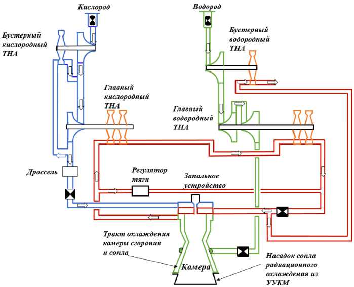
Рис. 1. Пневмогидравлическая схема двигателя РД-0146 безгазогенераторной схемы
Fig. 1. Pneumohydraulic engine diagram RD-0146 of an expanded cycle circuit
Computational study of the increase in the specific thrust impulse at different pressure levels in the combustion chamber of a liquid-propellant rocket engine
For this study, a mathematical model of a liquid-propellant rocket engine was worked out, which makes it possible to evaluate the geometric and energy parameters of the engine for a number of variable initial data. The study was carried out at different pressures in the CC, from a nominal pressure of 8 up to 15.5 MPa with a pressure step of 0.5 MPa.
Thermodynamic parameters in the mathematical model in a wide range of pressures and oxidizer excess coefficients were calculated using the Astra-M program for thermodynamic calculation of combustion products and individual working fluids. All results obtained are summarized to the database of the mathematical model and are used to calculate the geometric and energy parameters of the engine, as well as the flow path of the gas-dynamic engine passage.
The calculation of the energy and geometric parameters of the engine was carried out according to the method [19].
Depending on the required task, it is possible to increase the SIT with the help of the following measures:
-
1. Change in outlet pressure in the LRE nozzle (increase in expansion ratio).
-
2. Adjustment of the excess oxidizer ratio in the LRE chamber.
-
3. Increase in pressure in the CC.
The first method increases the overall dimensions and weight of the engine itself. In addition, nozzles at high expansion ratios are difficult to work out during ground tests of the engine (a more efficient ejector is needed at low pressures at the nozzle exit).
The second method is implemented with a decrease in the excess oxidizer ratio, which increases the mass consumption of fuel and, consequently, increases the mass of tanks in the engine supply system. Also, this reduces the temperature of the gas in the chamber, which means that the heating of the fuel and the power of the turbines also decrease. With an increase in excess oxidizer ratio, the SIT decreases.
The third method is the most preferable, because, with an increase in fuel heating and constant thrust, it is possible to increase the turbine power and the pressure of supplying components to the compressor station, while reducing the overall dimensions, mass flow and weight of the LRE itself.
The calculated-theoretical dependences of the parameters and geometry of the engine on the pressure change in the combustion chamber are given below.
Figure 2 shows the dependence of the total mass flow into the engine and ASI on the pressure in the combustion chamber. As can be seen from Fig. 2, ASI increases with increasing pressure in the CC from 463 to 474.5 s, and the total mass fuel consumption drops from 21.6 to 21.08 kg/s.
The mathematical model takes into account the change in the temperature of the combustion product from the excess oxidizer ratio and the pressure in the combustion chamber. Fig. 3 shows the dependence of the combustion product temperature on the pressure in the combustor. The temperature increases from 3516 (for a pressure in the CC of 8 MPa) to 3587 K (for a pressure in the CC of 15.5 MPa).
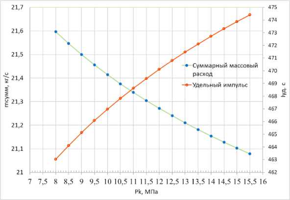
Рис. 2. Зависимость суммарного массового расхода в двигатель и УИТ от давления в КС
-
Fig. 2. Dependence of the total mass flow rate into the engine and ASI on the pressure in the CC
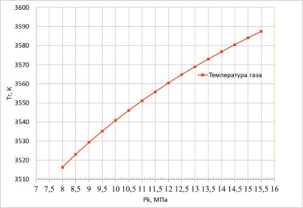
Рис. 3. Зависимость температуры продуктов сгорания от давления в КС
-
Fig. 3. Dependence of the temperature of combustion products on the pressure in CС
Figure 4 shows the dependence of the outflow velocity at the nozzle exit on the pressure in the combustor. According to the calculations, the exhaust velocity at the nozzle exit increases from 4262 up to 4383 m/s.
Further, the geometric parameters of the engine will be considered depending on the change in pressure in the CC.
Figures 5–8 show changes in the chamber diameter, critical and nozzle exit, as well as the length of the gas-dynamic profile (GDP) of the engine, depending on the pressure in the combustor.
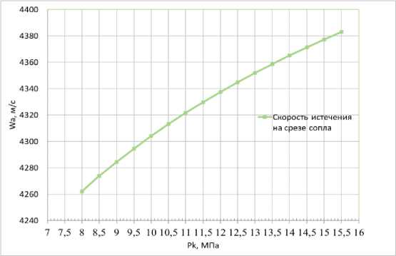
Рис. 4. Зависимость скорости истечения на срезе сопла от давления в КС
Fig. 4. Dependence of the flow rate at the nozzle section on the pressure in CС
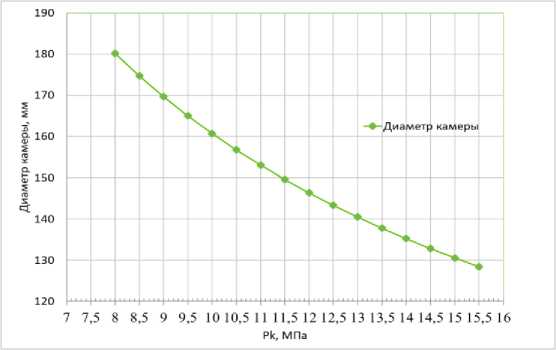
Рис. 5. Зависимость диаметра камеры сгорания от давления в КС
Fig. 5. Dependence of the diameter of the combustion chamber on the pressure in CC
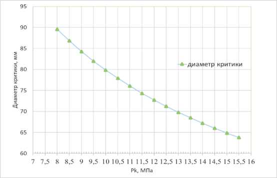
Рис. 6. Зависимость диаметра критики от давления в КС
Fig. 6. Dependence of the diameter of the critique on the pressure in the CC
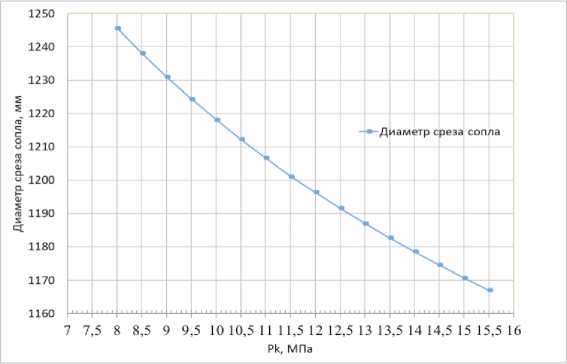
Рис. 7. Зависимость диаметра среза сопла от давления в КС
Fig. 7. Dependence of the nozzle cut-off diameter on the pressure in CC
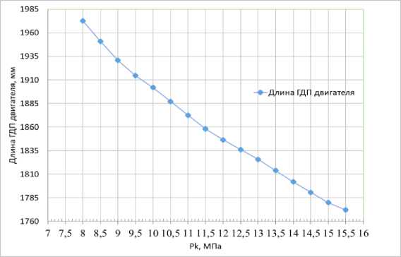
Рис. 8. Зависимость длины ГДП двигателя от давления в КС
Fig. 8. The dependence of the length of the GDP engine on the pressure in the CC
According to the above dependences, a trend in the change in the geometry of the engine gas turbine engine can be observed. The chamber diameter is reduced from 180 to 128.3 mm. The diameter of the criticism is reduced from 89.5 to 63.7 mm. The nozzle cut diameter is reduced from 1244.6 to 1166.9 mm. The length of the gas turbine engine is reduced from 1972.5 to 1772 mm.
In accordance with the given dependencies, it can be concluded that the overall dimensions of the engine decrease with increasing pressure in the CC, therefore, the mass of the engine also decreases.
Calculation of engine cooling with a pressure in the CC of 8 MPa with internal chamber finning
According to the calculation of the energy linkage of the engine, the parameters at the input were obtained in CL. These values were fixed and assigned as boundary conditions.
To increase the pressure in the CC, it is necessary to increase the heating of the refrigerant in the CL at a moderate thermal state (TS) of the design of the chamber body and nozzle. An increase in the heating of the refrigerant is possible due to the placement of additional fins inside the CC. Internal fins act as heat transfer intensifiers and increase the lateral surface area on the gas side, which affects heating.
The main task of calculating cooling in a generatorless engine circuit is to analyze the maximum possible fuel heating at a moderate TS of the LRE body structure.
The engine uses two methods of thermal protection of the casing - through-flow cooling with fuel with regeneration (return) of heat back to the engine case and radiation cooling with the use of a nozzle extension made of carbon composite material.
The complete GDP LRE with a nozzle extension is shown in fig. 9.
Further, in the cooling calculations, the nozzle carbon nozzle is not taken into account and only the engine segment with the organization of regenerative-flow cooling is considered.
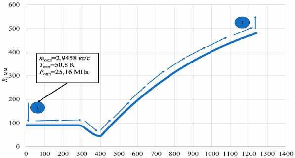
The cooling scheme of the cooled part of the LRE without a nozzle extension with the main parameters at the entrance to the CL is shown in Fig. 10.
For additional cooling of the internal longitudinal fins with still cold hydrogen, a direct-flow cooling scheme was proposed and calculated, in which the refrigerant is supplied in the CC and exits in the cut section with a coordinate of 1240.7 mm and a diameter of 960.59 mm.
The cross section of the combustion chamber with internal fins is shown in Fig. 11, where 1 is the inner shell, 2 are the main CL ribs, 3 is the CL channel, 4 are the corners rounded along the radius forming the CL channel, 5 are additional internal profiled fins, 6 is the outer profiled shell.
The height of the inner fin used in the calculation is 2.8 mm. The thickness of the fin is 1.2 mm. The number of fins is 200 pieces. The pitch along the base of the fin is 2.83 mm. The pitch along the end of the fin is 2.91 mm.
Fig. 12 and 13 show the heating and hydraulic losses of the cooler, Fig. 14 and 15 show thermal state of the inner wall of the chamber and thermal state of the end face of the inner fins.
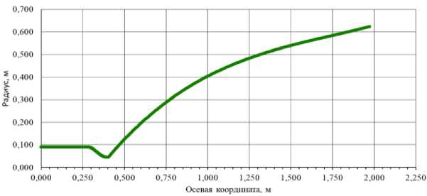
Рис. 9. Полный ГДП двигателя РД-0146
Fig. 9. Full GDP engine RD-0146
X, мм
•Газодинамический профиль
Рис. 10. Предложенная схема охлаждения двигателя РД 0146
Fig. 10. The proposed cooling scheme of the RD 0146 engine
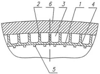
Рис. 11. ТО с продольными дополнительным газовыми рёбрами
Fig. 11. CL with longitudinal additional gas fins
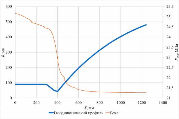
Рис. 12. Изменение давления охладителя по длине ГДП
Fig. 12. Change of the cooler pressure along the length of the GDP
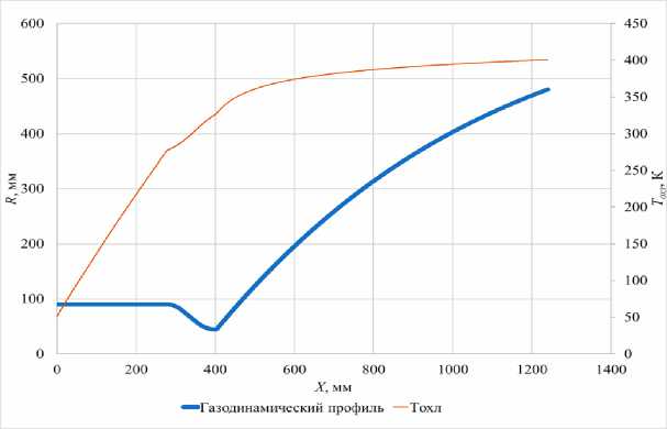
Рис. 13. Изменение температуры охладителя по длине ГДП
Fig. 13. The change in the temperature of the cooler along the length of the GDP
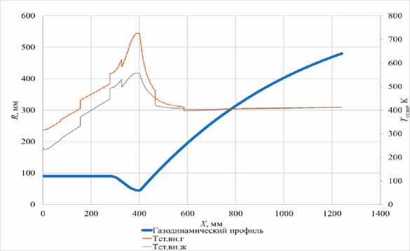
Рис. 14. ТС внутренней стенки со стороны газа и жидкости по длине ГДП
Fig. 14. TS of the inner wall from the gas and liquid side along the length of the GDP
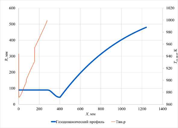
Рис. 15. ТС внутренних рёбер по длине ГДП
Fig. 15. TS of internal gas fins along the length of the GDP
As a result of the calculation, the following results were obtained:
– the temperature of the cooler at the outlet from the CL was 400.74 K;
-
- pressure of the cooler at the outlet - 21.27 MPa;
-
– maximum wall temperature on the gas side – 726.63 K;
-
– maximum wall temperature on the liquid side – 557.18 K;
-
– the maximum temperature of the inner fins is 999 K.
According to the results of energy matching, heating of hydrogen to 400 K provides a pressure in the combustor up to 10.5 MPa, while ASI, according to calculations in the mathematical model and Fig. 2, increases by 5 s.
Further, the GDP profile will be recalculated for a pressure in the CC of 10.5 MPa and a verification calculation of cooling will be performed with the determination of the thermal-hydraulic parameters of the engine cooling system.
Calculation of engine cooling with pressure in the combustion chamber of 10.5 MPa and internal chamber fins
Graphs of heating and hydraulic resistance are not given, only numerical total values at the outlet from CL are given.
Fig. 16 and 17 show the thermal state of the inner wall of the chamber and the end of the inner fins [20].
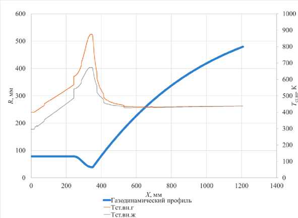
Рис. 16. ТС внутренней стенки со стороны газа и жидкости по длине ГДП
Fig. 16. Thermal state of the inner wall from the gas and liquid side along the length of the GDP
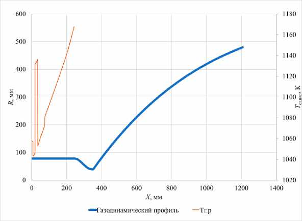
Рис. 17. ТС внутренних рёбер по длине ГДП
Fig. 17. Thermal state of internal gas fins along the length of the GDP
As a result of the calculation, the following results were obtained:
-
– the temperature of the cooler at the outlet from the CL was 426.46 K;
-
- pressure of the cooler at the outlet - 21.91 MPa;
– maximum wall temperature on the gas side – 875.39 K;
– maximum wall temperature on the liquid side – 673.42 K;
– the maximum temperature of the inner ribs is 1167 K.
Conclusion
A mathematical model for calculating the chamber of a gasless liquid-propellant rocket engine has been developed, which makes it possible to determine the optimal engine cooling scheme depending on the technical specifications.
At a pressure 8 and 10.5 MPa in the CC, a direct current engine cooling scheme is proposed.
According to the calculation results, it is possible to increase the pressure in the combustor from 8 to 10.5 MPa by placing longitudinal fins 2.8 mm high and 1.2 mm thick inside the chamber. Due to the increase in the heat exchange surface, hydrogen can be heated up to 424 K, which is 124 K more than in the prototype engine RD 0146, while the specific impulse increases by 468 s, which is 5 s higher than that of the prototype engine.
With an increase in pressure in the combustion chamber by 10.5 MPa, the overall dimensions of the engine and the length of the engine itself decrease.
A further increase in the specific impulse of the engine is possible by changing the output pressure at the nozzle exit (increasing the degree of expansion of the nozzle), while increasing the length of the engine and the diameter of the nozzle exit, for example, as in the RD-0146D LRE or AECE (Advanced Expander Cycle Engine) LRE), this will give an increase of up to 5 s in terms of specific thrust impulse (an increase in the dimensions and mass of the engine). It is also possible to increase the specific impulse by changing the excess oxidizer ratio in the combustion chamber.
References Increasing the specific impulse of an oxygen-hydrogen liquid rocket engine by in-creasing heat transfer in the combustion chamber
- Nesterov V. E., Rudakov V. B., Makarov V. I. [Analysis of the main tasks of experimental test-ing of a reusable rocket and space system]. Vestnik MAI. 2013, Vol. 20, No. 5, P. 77–85 (In Russ.).
- Shlyahov V. I. Pnevmogidrosistemy kriogennyh dvigatelnyh ustanovok mezhorbital'nyh buksi-rov [Pneumohydrosystems of cryogenic propulsion systems of interorbital tugs]. Moscow, MAI Publ., 1991, 61 p.
- Zatonskij A. V. Chislennoe modelirovanie i raschet techeniya I teploobmena v sisteme s mezhkanalnoj transpiraciej teplonositelya. Kand. Dis. [Numerical modeling and calculation of flow and heat transfer in a system with interchannel transpiration of a coolant. Cand. Diss.]. Moscow, MGTU Publ., 1996, 106 p.
- Bessard R., Delauer R. Yadernye dvigateli dlya samoletov I raket [Nuclear engines for aircraft and rocket]. Moscow, Military Publishing House Ministry of Defense of the USSR Publ., 1967, 398 p.
- Demyanko Yu. G., Konyuhov G. V., Koroteev A. S. Yadernye raketnye dvigateli [Nuclear rocket engines]. Moscow, Norma-inform Publ., 2001, 415 p.
- Dolgopolov C. Yu., Lomov I. V., Shamanin I. V. Vvedenie v yaderno-vodorodnuyu energetiku [Introduction to nuclear and hydrogen energy]. Tomsk, TPU Publ., 2008, 168 p.
- Kirdyushkin Yu. S. [The potential of hydrogen fuel for civil aviation of the future]. Scientific bulletin of MGTU GA. 2013, Vol. 194, P. 110–113 (In Russ.). DOI: 10.18698/2541-8009-2017-12-205.
- Zagashvili Yu. V., Levihin A. A., Kuz'min A. M. [Technology of hydrogen production using small-sized transportable installations based on high-temperature synthesis gas generators]. Questions of materials science. 2017, No. 2, P. 92–109 (In Russ.).
- Zagashvili Yu. V., Levihin A. A., Kuz'min A. M. [Fundamentals of designing three-component synthesis gas generators]. Oil and gas chemistry. 2017, No. 4, P. 9–16 (In Russ.).
- Zagashvili Yu. V., Levihin A. A., Kuz'min A. M. [Experimental installations based on high-temperature reactors for solving problems of gas chemistry, petrochemistry and ecology]. Problems of geology, development and operation of deposits and transportation of hard-to-recover hydrocarbon reserves. 2018, P. 229–234 (In Russ.).
- Polyakov T. V. Sostoyanie i perspektivy vodorodnoj energetiki v Rossii i mire [The state and prospects of hydrogen energy in Russia and the world]. Available at: https://mgimo.ru/files/ 120132/polyakova_vodorod.pdf (accessed 10.4.2022).
- Piunov V. Yu., Nazarov V. P., Kolomentsev A. I. [Improving the energy characteristics of ox-ygen-hydrogen liquid-propellant rocket engines of upper stages of methods for optimizing design schemes]. Vestnik MAI. 2017, Vol. 24, No. 3, P. 23–33 (In Russ.).
- Yoshihiro Naruo., Nobuhiro Tanatsugu.,Koichi Suzuki. Development study of LOX/LH2 High Pressure Expander Cycle Engine. JSTS. Vol. 4, No.1, P. 11–20.
- Pascal Pempie., Luca Boccaletto. LOX/CH4 EXPANDER UPPER STAGE ENGINE. 55 th International Astronautical Congress. October 2004, Vancouver, British Columbia.
- Bregvadze D. T., Gabidulin O. V. [Application of oxygen + methane fuel in liquid rocket en-gines]. Polytechnic Youth Magazine. 2017, No. 12, P. 1–13 (In Russ.). DOI: 10.18698/2541-8009-2017-12-205.
- Chudina Yu. S. Rabochie processy v raketnom dvigatele maloj tyagi na gazoobraznyh kompo-nentah topliva kislorod i metan. Kand. Dis. [Working processes in a low-thrust rocket engine on gase-ous fuel components oxygen and methane. Cand. Diss.]. Moscow, MAI Publ., 2014, 167 p.
- Belyakov V. A., Vasilevskiy D. O. [Perspective circuit solutions of liquid rocket engine by expanded cycle]. Vestnik PNIPU. Aerospace science. 2019, Vol. 58, P. 69–86 (In Russ.). Doi: 10.15593/2224-9982/2019-58-06.
- Kovalev B. K. Razvitie raketno-kosmicheskih sistem vyvedeniya [Development of rocket and space launch systems]. Moscow, Bauman Moscow state technical University Publ., 2014, 398 p.
- Dobrovolsky M. V. Zhidkostnye raketnye dvigateli, Osnovy proektirovaniya [Liquid rocket engines, Fundamentals of design]. Moscow, Bauman Moscow state technical University Publ., 2016, 461 p.
- Vasil'ev E. N. [Calculation of heat transfer characteristics of the finned wall]. Siberian Journal of Science and Technology. 2020, Vol. 21, No. 2, P. 226–232 (In Russ.).
